2017 FIAT TIPO 5DOORS STATION WAGON Page 92
[x] Cancel search: Page 92Page 2 of 264

This Owner Handbook is intended to show the vehicle's operating conditio\
ns.
For the enthusiast user who wants to have insights, curiosities and deta\
iled information about the characteristics and functions
of the vehicle, Fiat gives the opportunity to consult a dedicated sectio\
n which is available in electronic format.
ONLINE VEHICLE OWNER HANDBOOK
The following symbol is reported within the text of the Owner Handbook, next to the subjects \
for which details are provided.
Go to the www.mopar.eu/owner
website and access your personal area.
The “Maintenance and care” page includes all the information about\
your vehicle and the link to access eLUM, where you will find
all the details of the Owner Handbook.
Alternatively, to access this information, go to the Internet website at\
http://aftersales.fiat.com/elum/
.
The eLUM website is free and will allow you, among many other things, to easily c\
onsult the on-board documents
of all the other vehicles of the Group.
Have a nice reading and happy motoring!
We really know your car because we invented, designed and built it: we r\
eally know every single detail.
At Fiat Service authorised workshops you can find technicians directly trained by us,
offering quality and professionalism for all service operations.
Fiat workshops are always close to you for the regular servicing operati\
ons, season checks and practical recommendations by our experts.
With Original Parts distributed by MOPAR
®, you maintain the reliability, comfort
and performance features that you bought your new car for over time.
Always ask for Genuine Parts for the components used on our cars; we rec\
ommend them because
they come from our steady commitment in research and development of high\
ly innovative technologies. For all these reasons: rely on Genuine Parts, because they are the only ones designed by FCA for your car.
SAFETY:
BRAKING SYSTEMENVIRONMENT: PARTICULATE FILTERS, CLIMATE CONTROL MAINTENANCECOMFORT: SUSPENSION
AND WINDSCREEN WIPERS PERFORMANCE: SPARK PLUGS, INJECTORS AND BATTERIESLINEACCESSORI
ROOF RACK BARS, WHEEL RIMS
WHY CHOOSING GENUINE PARTS
COP TIPO 5 DOORS UM SW GB.qxp_500 UM ITA 31/05/16 17:11 Pagina 2
Page 5 of 264
USE OF THE OWNER HANDBOOK
Each time direction instructions (left/right or forwards/backwards) about the vehicle are given, these must be understood as
regarding an occupant in the driver's seat. Special cases not complying with this rule will be specified as appropriate in the text.
The figures in the Owner Handbook are provided by way of example only: this might imply that some details of the image do
not correspond to the actual arrangement of your vehicle. In addition, the Handbook has been conceived considering vehicles
with steering wheel on the left side; it is therefore possible that on vehicles with steering wheel on the right side, the position or
construction of some controls is not exactly mirror-like with respect to the figure.
To identify the chapter with the information needed you can consult the index at the end of this Owner Handbook.
Chapters can be rapidly identified with dedicated graphic tabs, at the side of each odd page. A few pages further there is a key
for getting to know the chapter order and the relevant symbols in the tabs. There is in any case a textual indication of the
current chapter at the side of each even page.
Page 76 of 264
43) 44) 45) 46) 47)
TC (Traction Control)
SYSTEM
The system automatically operates in
the event of slipping, loss of grip on wet
roads (aquaplaning) and acceleration on
slippery, snowy or icy roads, etc. on
one or more drive wheels. Depending
on the slipping conditions, two different
control systems are activated:
if the slipping involves both drive
wheels, the system intervenes, reducing
the power transmitted by the engine;
if the slipping only involves one of the
drive wheels, the BLD (Brake Limited
Differential) function is activated,
automatically braking the wheel which
is slipping (the behaviour of a
self-locking differential is simulated).
This will increase the engine torque
transferred to the wheel which isn't
slipping. This function remains active
even if the "Systems partially disabled"
and "Systems disabled" modes are
selected (see description in the
following pages).
System intervention
The intervention of the system is
indicated by the flashing of the
warning light on the instrument
panel, to inform the driver that the
vehicle is in critical stability and grip
conditions.
48) 49) 50) 51) 52)
PBA (Panic Brake
Assist) SYSTEM
The PBA system is designed to improve
the vehicle’s braking capacity during
emergency braking.
The system detects emergency braking
by monitoring the speed and force with
which the brake pedal is pressed, and
consequently applies the optimal brake
pressure. This can reduce the braking
distance: the PBA system therefore
completes the ABS.
Maximum assistance from the PBA
system is obtained by pressing the
brake pedal very quickly. In addition, the
brake pedal should be pressed
continuously during braking, avoiding
intermittent presses, to get the most
out of the system. Do not reduce
pressure on the brake pedal until
braking is no longer necessary.
The PBA system is deactivated when
the brake pedal is released.
54) 54) 55)
HHC (Hill Hold Control)
SYSTEM
This is an integral part of the ESC
system and facilitates starting on
slopes, activating automatically in the
following cases:
uphill: vehicle stationary on a roadwith a gradient higher than 5%, engine
running, brake pressed and
transmission in neutral or gear other
than reverse engaged;
downhill: vehicle stationary on a road
with a gradient higher than 5%, engine
running, brake pressed and reverse
gear engaged.
When setting off, the ESC system
control unit maintains the braking
pressure on the wheels until the engine
torque necessary for starting is
reached, or in any case for a maximum
of 2 seconds, allowing your right foot to
be moved easily from the brake pedal
to the accelerator.
When two seconds have elapsed,
without starting, the system is
automatically deactivated, gradually
releasing the braking pressure. During
this release stage it is possible to hear a
typical mechanical brake release noise,
indicating the imminent movement of
the car.
56) 57)
ERM (Electronic Rollover
Mitigation) SYSTEM
The system monitors the tendency of
the wheels to rise from the ground if the
driver performs extreme manoeuvres
like quick steering to avoid an obstacle,
especially in poor road conditions.
74
SAFETY
Page 85 of 264
OCCUPANT
PROTECTION
SYSTEMS
Some of the most important safety
equipment of the vehicle comprise the
following protection systems:
seat belts;
SBR (Seat Belt Reminder) system;
head restraints;
child restraint systems;
Front air bags, side air bags and
drop down air bags (where provided).
Read the information given the following
pages with the utmost care. It is of
fundamental importance that the
protection systems are used in the
correct way to guarantee the maximum
possible safety level for the driver and
the passengers.
For the description of the head restraint
adjustment see the "Head restraints"
paragraph in the "Knowing your vehicle"
chapter.
SEAT BELTS
All vehicle seats are equipped with seat
belts with three anchor points and a
retractor.
The retractor mechanism operates
locking the belt in the event of sharp
braking or strong deceleration due to
an impact. This allows the belt strap to
slide freely and to adapt to the body of
the occupant. In the event of an
accident, the belt will lock reducing the
risk of impact inside the passenger
compartment and of being projected
outside the vehicle.
The driver is responsible for respecting,
and ensuring that all the other
occupants of the vehicle also respect,
the local laws in force in relation to the
use of the seat belts.
Always fasten the seat belts before
setting off.
USING THE SEAT BELTS
The seat belt should be worn keeping
the chest straight and rested against
the backrest.
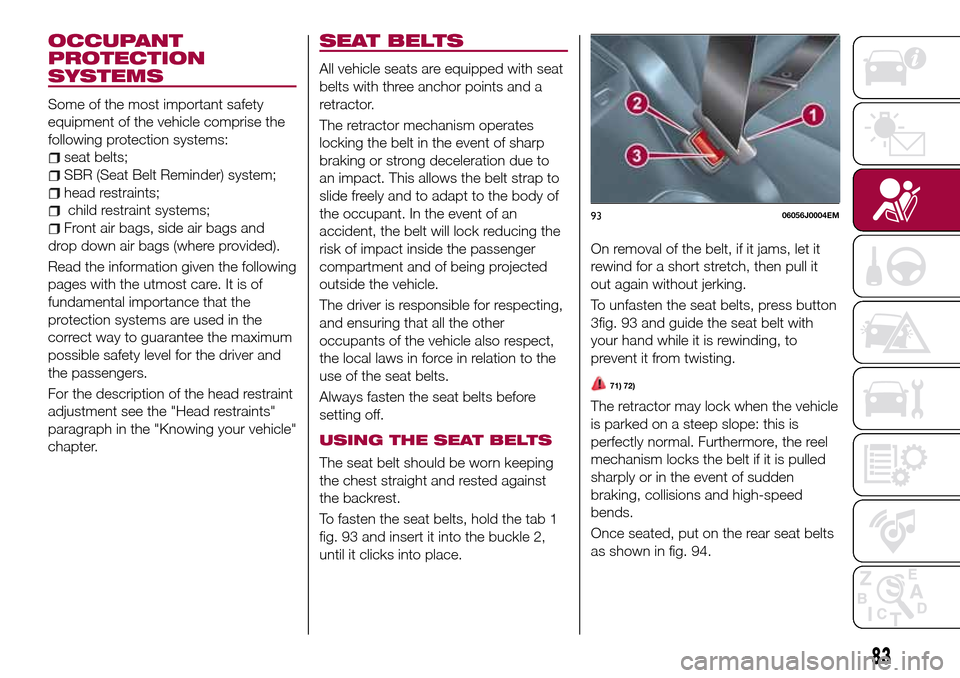
To fasten the seat belts, hold the tab 1
fig. 93 and insert it into the buckle 2,
until it clicks into place.On removal of the belt, if it jams, let it
rewind for a short stretch, then pull it
out again without jerking.
To unfasten the seat belts, press button
3fig. 93 and guide the seat belt with
your hand while it is rewinding, to
prevent it from twisting.
71) 72)
The retractor may lock when the vehicle
is parked on a steep slope: this is
perfectly normal. Furthermore, the reel
mechanism locks the belt if it is pulled
sharply or in the event of sudden
braking, collisions and high-speed
bends.
Once seated, put on the rear seat belts
as shown in fig. 94.
9306056J0004EM
83
Page 119 of 264
“Adaptive Cruise Control” mode
to hold an appropriate distance
between vehicles (a dedicated message
is shown on the instrument panel
display);
electronic “Cruise Control” mode
to hold the vehicle at a constant
preset speed.
To change the operation mode, use the
button on the steering wheel (see that
described on the following pages).
The "electronic Cruise Control" does
not vary the speed according to the
presence or not of vehicles ahead.
Always adjust the speed according to
traffic conditions.
ADAPTIVE CRUISE
CONTROL ACTIVATION/
DEACTIVATION
Activation
To activate the device, press and
release the button
fig. 122.With the device activated and ready to
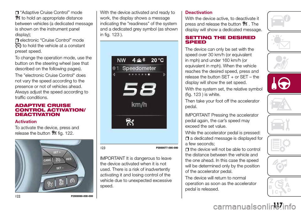
work, the display shows a message
indicating the "readiness" of the system
and a dedicated grey symbol (as shown
in fig. 123 ).
IMPORTANT It is dangerous to leave
the device activated when it is not
used. There is a risk of inadvertently
activating it and losing control of the
vehicle due to unexpected excessive
speed.
Deactivation
With the device active, to deactivate it
press and release the button
. The
display will show a dedicated message.
SETTING THE DESIRED
SPEED
The device can only be set with the
speed over 30 km/h (or equivalent
in mph) and under 160 km/h (or
equivalent in mph). When the vehicle
reaches the desired speed, press and
release the button SET + or SET – the
display will show the set speed.
With the system set, the relative symbol
(fig. 123 ) is white.
Then take your foot off the accelerator
pedal.
IMPORTANT Pressing the accelerator
pedal again, the car’s speed may
exceed the set value.
While the accelerator pedal is pressed:
a dedicated message is displayed for
a few seconds;
the device will not be able to control
the distance between the vehicle and
the one ahead. In this case the speed
will be determined only by the position
of the accelerator pedal.
The device will return to normal
operation as soon as the accelerator
pedal is released.
122P2000060-000-000
123P2000077-000-000
117
Page 133 of 264
IN AN EMERGENCY
A punctured tyre or a burnt-out bulb?
At times, a problem may interfere with
our journey.
The pages on emergencies can help
you to deal with critical situations
independently and with calm.
In an emergency we recommend that
you call the freephone number found in
the Warranty Booklet.
It is also possible to call the national or
international universal freephone
number to search for the nearest Fiat
Dealership.HAZARD WARNING LIGHTS.....132
BULB REPLACEMENT........132
REPLACING FUSES..........142
CHANGING A WHEEL.........148
FIX&GO AUTOMATIC KIT.......152
JUMP STARTING............155
FUEL CUT-OFF SYSTEM.......157
TOWING THE VEHICLE........159
131
Page 148 of 264

UNDER DASHBOARD CONTROL UNIT
fig. 166
USERSFUSE AMPERE
Front door unlocking (driver side) 1 7.5
Front door unlocking (passenger side) 2 7.5
Rear door unlocking (left) 3 7.5
Rear door unlocking (right) 4 7.5
LUGGAGE COMPARTMENT FUSE BOX
fig. 169
USERSFUSE AMPERE
Rear 12 V socket F97 15
Driver's front seat heater F99 10
Passenger side front seat heater F92 10
Driver's front seat lumbar adjustment F90 10
WARNING
134)If the replaced fuse blows again, contact a Fiat Dealership.
135)Never replace a fuse with another with a higher amp rating; DANGER OF FIRE
136)If a fuse NOT indicated in this or the previous page is used, contact a Fiat Dealership.
137)Before replacing a fuse, make sure that the ignition device is at STOP, that the key, if mechanical, has been removed and that all devices
are switched off and/or disconnected.
146
IN AN EMERGENCY
Page 180 of 264

"quick-type" battery charger is used
with the battery fitted on the vehicle,
before connecting it disconnect both
cables of the battery itself. Do not use a
"quick-type" battery charger to provide
the starting voltage.
VERSIONS WITHOUT
STOP/START SYSTEM
To recharge, proceed as follows:
disconnect the terminal from the
negative battery pole;
connect the charger cables to the
battery terminals, observing the polarity;
turn on the charger;
when it is recharged, turn the
charger off before disconnecting it from
the battery;
reconnect the terminal to the
negative battery pole.
VERSIONS WITH
STOP/START SYSTEM
(where provided)
To recharge, proceed as follows:
disconnect the connector 1
fig. 202 (pressing the button 2) from the
sensor 3 monitoring the battery
conditions, on the negative pole (–) 4 of
the battery;
connect the positive cable (+) of the
battery charger to the positive battery
terminal 5 and the negative cable (–) to
sensor terminal 4 as shown;
turn on the battery charger. At the
end of the charging process, switch the
battery charger off;
after having disconnected the
charging device, reconnect connector
1 to the sensor 3 as shown.
SERVICING
PROCEDURES
The following pages contain the rules
on therequiredmaintenance
envisaged by the technical personnel
who designed the vehicle.
In addition to these specific
maintenance instructions specified for
routine scheduled servicing, there are
other components which may require
intervention or replacements over the
vehicle’s life cycle.
ENGINE OIL
Engine oil level check
74)
To ensure correct engine lubrication, the
oil must always be kept at the
prescribed level (see "Engine
compartment" in this chapter).
ENGINE OIL FILTER
Replacing the engine oil filter
The engine oil filter must be replaced
each time the engine oil is changed.
It is advisable to replace it with a
genuine spare part, specifically
designed for this vehicle.
20209036J0001EM
178
SERVICING AND CARE
71) 72)
73)