Page 17 of 296

Manual opening of the second
swing door
Pull the handle C fig. 12 in the direction
indicated by the arrow.
The rear swing-doors are equipped with
a spring loaded system that locks
them at an approx. angle of 90 degrees
during opening.Electrical closure from inside
Close the two rear swing doors (first
left, then right) and press the button D
fig. 13 on the electric window control
panel.
The opening angle of the two doors
may be increased for more convenient
loading and unloading.To do this, press the button A fig. 14 so
that the door can be opened by about
180 degrees.
9) 10) 11) 12) 13) 14) 15)
2)
WARNING
6)Once the dead lock device is engaged it
is impossible to open the doors from
inside the vehicle. Before engaging the
system please therefore check that there is
no-one left on board. If the remote control
battery is flat, the system can be
disengaged only by inserting the key metal
insert in either of the door locks as
described previously: in this case the
device remains active only for the rear
doors.
7)Before leaving the vehicle parked with
sliding doors open, always check that
the latch is engaged.
8)Do not move the vehicle with side doors
open.
11F1A0121
12F1A0122
13F1A0123
14F1A0124
15
Page 18 of 296

9)Before setting off after parking or before
moving the vehicle in any way, ensure
the footboard is fully stowed away.
Because the movement of the footboard is
controlled by that of the sliding side door,
incomplete stowing of the footboard or
non-closure of the rear doors is indicated
by the lighting of a warning light
on
the instrument panel.
10)This spring loaded system has
activation forces that were designed for
optimum comfort. Accidental knocks or a
strong gust of wind may release the
springs and let the doors close
spontaneously.
11)With the doors opened to 180 degrees,
no locking system is effective. Do not use
this opening with the vehicle parked on
a gradient or when it is windy.
12)It is forbidden to drive the vehicle with
the footboard open.
13)Do not use the retracted footboard for
getting up or down the load compartment.
14)Make sure that the footboard is suitably
locked by the provided retaining systems
before, after and during its use. An
incomplete opening or closing might cause
an improper movement of the footboard
with risks arising for the operator and
external users.
15)The footboard lightly projects from the
vehicle even if retracted; therefore, when
rear parking sensors are provided, their
operating range is lightly reduced.
WARNING
2)The footboard presence may reduce the
ramp approach angles; it is therefore
recommended, in case of a very steep
ramp, to be very careful in order not to
damage the footboard.
SEATS
16)
3)
Longitudinal adjustment
Lift lever A fig. 15 and push the seat
forwards or backwards: in the driving
position your arms should rest on
the steering wheel rim.
17)
Height adjustment
To raise the seat: while seated, move
the lever B fig. 15 (front part of the
seat) or the lever C fig. 15 (rear part of
the seat) upwards and lift your body
weight off the part of the seat that must
be raised.
15F1A0021
16
KNOWING YOUR VEHICLE
Page 19 of 296

To lower the seat: whilst sitting, move
the lever B (front part of the seat) or
the lever C (rear part of the seat)
upwards and position your body weight
on the part of the seat to be lowered.
Backrest angle adjustment
Turn the knob D fig. 15.
18)
Lumbar adjustment
Operate the knob E fig. 16 to adjust.
SPRUNG SEAT
The seat is equipped with a mechanical
spring system and hydraulic shock
absorber to ensure maximum comfort
and safety. The system of springs
also effectively absorbs impact from
uneven road surfaces.See the description in the "Seats"
section for the lengthwise adjustments,
height adjustments, backrest
adjustment, lumbar adjustment and
armrest adjustment.
Ballast weight adjustment
Use the knob A fig. 17 to set the
desired adjustment according to your
body weight, in the range 40 kg to 130
kg.
19) 20) 21) 22) 23)
SEAT WITH REVOLVING
BASE
(for versions/markets, where provided)
It may be turned through 180° toward
the seat on the opposite side. Operate
the control A fig. 18 to turn the seat.
Before turning the seat, it must be
moved forward and only then adjusted
longitudinally fig. 19.CARGO SPACE
(For versions/markets, where provided)
Depending on the version, you can
request an additional load compartment
fig. 20 located behind the cab.
16F1A002217F1A0023
18F1A0025
12
19F1A0026
17
Page 20 of 296

PANORAMA VERSIONS
Adjustment of passenger seat
reclining backrest
Turn the knob A fig. 21.
Access to second row seats
To access the second row of seats,
operate the lever B fig. 21 on the right
outside seat in the first row and tilt
the backrest forward, accompanying it
with your left hand.When the seat is restored to its normal
position, it engages with the retaining
device without the need to operate the
lever again.
On the one-piece Panorama seat in the
second row both side seats are fixed.
Folding middle seat backrest (2nd -
3rd row)
Lift the lever C fig. 21 and tilt the
backrest forward.
A hard surface on the back of the
middle seat is for use as an armrest
and table with cup holders.
Operate the lever to reposition the
backrest.
To lower the backrest of the middle
seat in the second row, remove the
head restraint to make it easier to
adjust the backrest of the middle seat
in the first row.COMBI VERSIONS
Easy Entry position
Lift the lever A fig. 22 and tilt the
backrest forward.
Stacked position
Proceed as follows:
– remove the head restraints from the
easy entry position;
– lift the lever B fig. 23 (located under
the lever A fig. 22) with your right hand;
– turn the backrest 5° towards the
rear area;
– fold the backrest forward with your
left hand.
24)
Removing the bench
IMPORTANT At least two people are
needed to remove the bench.
20F1A0041
21F1A0034
22F1A0035
18
KNOWING YOUR VEHICLE
Page 21 of 296

Proceed as follows to remove the
bench:
– from the stacked position, operate
the levers C and D fig. 24, rotating
them forward (as specified on the
adhesive label on the lower
crossmember);
– lift seat base forward;
– bring the seat to an upright position;
– from the vertical position, operate
the levers E and F fig. 25, rotating them
upwards;
– raise the bench from the floor and
remove it.
25)
FLEX FLOOR REAR SEAT
To release the seat, proceed as follows:
operate the rear release lever A fig.
26 to to aid releasing the safety catch
underneath it (movement1);
pull the black knob B fig. 26
(movement2);
lift the lever A (movement3), just
above the slide lock C fig. 27 (on the
side) to ensure that the system is held
up during the operations.When the base has been locked, it will
be possible to move the seat by
accompanying it with both hands to
move it forwards or backwards fig. 28.
It will also be possible to disassemble
it by pulling it at the points in which
its catches are free with respect to the
holes in the tracks; in that position
(easily found by sliding the base a little
and simultaneously pulling it out) the
seat can easily be removed fig. 29.
23F1A003624F1A0037
25F1A0038
26F1A0388
27F1A0389
19
Page 22 of 296

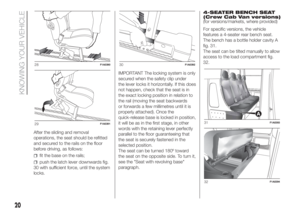
After the sliding and removal
operations, the seat should be refitted
and secured to the rails on the floor
before driving, as follows:
fit the base on the rails;
push the latch lever downwards fig.
30 with sufficient force, until the system
locks.IMPORTANT The locking system is only
secured when the safety clip under
the lever locks it horizontally. If this does
not happen, check that the seat is in
the exact locking position in relation to
the rail (moving the seat backwards
or forwards a few millimetres until it is
properly attached). Once the
quick-release base is locked in position,
it will be as in the first stage, in other
words with the retaining lever perfectly
parallel to the floor guaranteeing that
the seat is securely fastened in the
selected position.
The seat can be turned 180º toward
the seat on the opposite side. To turn it,
see the "Seat with revolving base"
paragraph.4-SEATER BENCH SEAT
(Crew Cab Van versions)
(for versions/markets, where provided)
For specific versions, the vehicle
features a 4-seater rear bench seat.
The bench has a bottle holder cavity A
fig. 31.
The seat can be tilted manually to allow
access to the load compartment fig.
32.
28F1A0390
29F1A0391
30F1A0392
31F1A0393
32F1A0394
20
KNOWING YOUR VEHICLE
Page 23 of 296

WARNING
16)All adjustments must be made with the
vehicle stationary.
17)After releasing the adjustment lever,
always check that the seat is locked on the
guides by trying to move it back and forth.
If it is not locked, the seat may move
unexpectedly and make you lose control of
the vehicle.
18)For maximum safety, keep the backrest
upright, lean back into it and make sure
the seat belt fits closely across your chest
and pelvis.
19)Before putting on the seatbelt, ensure
that the armrests are vertical (see
paragraph on "seat belts ”).
20)Before unfastening the belts and
getting out of the vehicle, ensure that the
outer armrest (door side) is fully raised.
21)All adjustments must be made with the
vehicle stationary. In particular, while
turning the seat, take care that it does not
interfere with the handbrake lever.
22)Ensure the seat is locked in driving
position before starting up the vehicle.
23)Do not place heavy loads on the flap
with the vehicle in motion because they
could be thrown against the vehicle
occupants in the event of sudden braking
or impacts, causing severe injury.24)Do not travel with passengers seated in
the 3rd row with the 2nd row bench folded
over. Do not place objects of any type on
the backrest of the 2nd row bench folded
over: in the event of impact or sharp
braking they could be thrown against the
occupants of the vehicle casing serious
injury. For more information, see the
contents of the adhesive plate located
under the bench.
25)When refitting the bench, ensure that it
is correctly locked to the floor guides.
WARNING
3)The fabric upholstery of your vehicle is
designed to withstand the normal wear
and tear of your vehicle for a long time.
You are however recommended to avoid
strong and/or continuous scratching
with clothing accessories such as metal
buckles, studs, Velcro fastenings and the
like, as these items cause stress of the
cover fabric that could lead to yarn
breaking and damage the upholstery.
STEERING WHEEL
The steering wheel position can be
adjusted axially.
To carry out the adjustment, proceed as
follows:
release the lever fig. 33 by pulling it
towards the steering wheel (position 2);
adjust the steering wheel;
block the lever by pushing it
forwards (position 1).
26) 27)
33F1A0040
21
Page 24 of 296

WARNING
26)Any steering wheel position adjustment
should only be carried out with the vehicle
stationary and the engine turned off.
27)It is absolutely forbidden to carry out
any after-market operation involving
steering system or steering column
modifications (e.g.: installation of anti-theft
device). This could badly affect
performance and safety, invalidate the
warranty and also result in the non-
compliance of the vehicle with approval
requirements.
REAR VIEW
MIRRORS
INTERIOR MIRROR
Lever A fig. 34 can be used to move
the mirror to two different positions:
normal or antiglare.
DOOR MIRRORS
Mirrors with manual adjustment
To adjust the mirrors, manually operate
on each of the two glasses of each
mirror.
28)
Mirrors with electrical adjustment
The electrical adjustment can only
be carried out with the ignition key in
the MAR-ON position.
To adjust the mirrors, turn the knob B
fig. 35 to one of the four positions: 1 left
mirror, 2 right mirror, 3 left wide angle,
4 right wide angle.After rotating the knob B on the mirror
to be adjusted, move it in the direction
shown by the arrows to adjust the
selected glass.
Mirror folding with manual
adjustment
When required (for example when the
mirror causes difficulty in narrow
spaces or at an automatic car washing
station) it is possible to fold the mirrors
manually moving them from position
1 to position 2 fig. 36.
If the mirror has been accidentally
rotated forwards (position 3), for
example due to an impact, it must be
manually returned to position 1.
29)
34F1A0353
35F1A0042
22
KNOWING YOUR VEHICLE