Page 153 of 284
DASHBOARD FUSE BOX
The fuse box fig. 125 is located near
the left side of the steering column and
the fuses can be accessed easily from
the lower part of the dashboard.
For fuse replacement, contact a Fiat
Dealership.
125F1B0193C
151
Page 154 of 284
BOOT FUSE BOX
Open inspection cover A fig. 126 and
access the fuses in fuse box B fig. 127.
126F1B0194C
127F1B0195C
152
IN AN EMERGENCY
Page 155 of 284
ENGINE COMPARTMENT FUSE BOX
USERSFUSE AMPERE
HornF10 10
Power supply for cigar lighter/power socket F84 20
DASHBOARD FUSE BOX
USERSFUSE AMPERE
Front electric window (passenger side) F33 20
Front electric window (driver side) F34 20
Supply for
Uconnect™system, Climate Control system, Electric door mirror folding,
EOBD system, USB port/AUX socket, rear side roof lights
(versions with sun roof)F36 15
Dead Lock device (Driver side door unlocking for
versions/markets, where provided)/Door unlocking/Central
locking/Electric tailgate unlockingF38 20
Rear left electric window F47 20
Rear right electric window F48 20
153
Page 156 of 284
BOOT FUSE BOX
NOTE The configuration of the boot may vary in accordance with the equipment on the vehicle.
Fuse box B
USERSFUSE AMPERE
HI-FI system F2 20
Electric sun roof F3 20
Front seat electric lumbar adjustment (driver guide) F4 7.5
Electric front seat adjustment (driver side) F5 30
Electric front seat adjustment (driver side and passenger side) F6 7.5
Electric front seat lumbar adjustment (driver side and passenger
side)F7 30
154
IN AN EMERGENCY
Page 157 of 284

WARNING
139)If the replaced fuse blows again,
contact a Fiat Dealership.
140)Never replace a fuse with another
with a higher amp rating; DANGER OF
FIRE
141)If a fuse NOT indicated in this or the
previous page is used, contact a Fiat
Dealership.
142)Before replacing a fuse, make sure
that the ignition device is at STOP, that the
key, if mechanical, has been removed and
that all devices are switched off and/or
disconnected.
IMPORTANT
66)Never replace a fuse with metal wires
or anything else.
67)If it is necessary to wash the engine
compartment, take care not to directly hit
the fuse box and the window wiper motor
with the water jet.
CHANGING A WHEEL
JACK
150) 151)
Please note that:
the jack weight is 2.8 kg;
the jack requires no adjustment;
the jack cannot be repaired and in
the event of a fault it must be replaced
by another genuine one;
no tool other than its cranking device
may be fitted on the jack.
Maintenance
prevent any dirt from depositing on
the "worm screw";
keep the "worm screw" lubricated;
never modify the jack.
Conditions for non-use
temperatures below −40°C;
on sandy or muddy ground;
on uneven ground;
on steep roads;
in extreme weather conditions:
thunderstorms, typhoons, hurricanes,
blizzards, storms, etc...
in direct contact with the engine or
for repairs under the car;
on boats.
CHANGING PROCEDURE
143) 144) 145) 146) 147) 148) 149)
Proceed as follows:
stop the vehicle in a position that is
not dangerous for oncoming traffic
where you can change the wheel safely.
The ground should be flat if possible,
and sufficiently firm;
stop the engine, engage the hazard
warning lights and the electric parking
brake;
engage first gear or reverse or, for
versions with automatic transmission,
move the lever to position P (Park);
wear the reflective safety jacket
(compulsory by law in certain countries)
before getting out of the vehicle;
open the boot and position the
reconfigurable load platform in an
inclined position (see "Boot" in the
"Knowing your vehicle" chapter);
take the tool bag provided, which is
secured to the luggage compartment
cover with specific fastenings. This bag
contains fig. 128: jack A; screwdriver B;
adaptor C for refuelling in the event of
an emergency; pin D for centring the
wheel (where provided, to be used in
the spare wheel fitting procedure);
special anti-theft nut E (where provided,
to be used in the wheel stud bolt
fitting/removal procedure); wedge F
wheels and the vehicle;
155
(where provided) for blocking the
Page 158 of 284
tow hook G; wrench H for the wheel
stud bolts and the jack; Allen key I for
emergency operation of the sun roof
(where provided);
raise the mat A fig. 129 and take the
space-saver wheel B;
bring the space-saver wheel and the
tool bag near the wheel to be replaced;
take the chock A fig. 130 (where
provided) and fold it out as shown
place the chock A on the wheel
diagonally opposite the one to be
replaced (see fig. 131) to prevent the
vehicle from moving irregularly when it
is lifted from the ground;
use the key A fig. 132 to loosen the
fixing stud bolts by about one turn. With
alloy rims it is recommended to "shake"
the vehicle to facilitate detachment of
the rim from the wheel hub;
position the jack under the vehicle,
near the wheel to be changed;
insert the key A fig. 133 on the
hexagonal part of the jack B to extend it
until the top splined area fits correctly
128F1B0218C
129F1B0219C
130F1B0220C
131F1B0221C
132F1B0223C
156
IN AN EMERGENCY
in the diagram;
Page 159 of 284

into the sidemember C of the vehicle,
next to the symbol
on the
sidemember itself;
alert any bystander that the vehicle is
about to be raised; all persons should
be kept away from the vehicle and
nobody must touch it until it has been
lowered;
use the key A to operate the jack
(clockwise) and lift the vehicle until the
wheel is several centimetres off the
ground;
use the key A to undo the stud bolts
completely and remove the punctured
tyre;
make sure the contact surfaces
between space-saver wheel and hub
are clean and free from impurities so
that the fixing stud bolts will not come
loose;
in order to facilitate fitting of the
space-saver wheel, tighten the centringpin in the higher hole of the wheel hub,
then fit the space-saver wheel,
screwing in the first stud bolt by hand
for at least two threads;
remove the centring pin and screw
in the other stud bolts by hand;
tighten all the retaining stud bolts
using the key A;
operate the key A (anticlockwise) on
the hexagonal part of the jack, in order
to lower the vehicle, then extract it;
use the key A to fully tighten the stud
bolts in a criss-cross fashion as per the
numerical sequence shown in fig. 134;
place the punctured tyre in the boot
upside down (with the outer part facing
upwards), then reposition the jack and
the used tools;
reposition the boot mat then
reposition the reconfigurable load
platform in a flat position (see "Boot" in
the "Knowing your vehicle" chapter).Restore the standard wheel as soon as
possible, because, once placed in the
associated compartment, the boot load
platform is rendered uneven as the
standard wheel is larger than the
space-saver wheel.
CHANGING A WHEEL
(versions with
subwoofer)
Versions with space-saver wheel
On these versions, the tools for
replacing the wheel are located in a
dedicated bag in the luggage
compartment.
In the case of a puncture, proceed as
follows:
open the luggage compartment and
then lift up the mat;
unscrew the locking device A
fig. 135, remove the space-saver spare
wheel B and fit it in place of the
punctured tyre, carrying out the
procedures described previously.
133F1B0224C
134F1B0225C
157
Page 160 of 284

When the operation is completed, lower
the luggage compartment mat and
position the punctured tyre on top of it,
ensuring that it is locked correctly so
that it doesn’t move during driving.
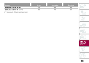
Versions with “Fix&Go Automatic”
kit
To find the “Fix&Go Automatic” kit,
open the luggage compartment then lift
up the mat: the kit A fig. 136 is located
on the right-hand side.
WARNING
143)If left in the passenger compartment,
the punctured wheel and jack constitute a
serious risk to the safety of occupants in
the event of accidents or sharp braking.
Therefore, always place both the jack and
punctured wheel in the dedicated housing
in the boot.
144)It is extremely dangerous to attempt
to change a wheel on the side of the
vehicle next to the driving lane: make sure
that the vehicle is at a sufficient distance
from the road, to avoid being run over.
145)Alert other drivers that the car is
stationary in compliance with local
regulations: hazard warning lights, warning
triangle, etc. Any passengers on board
should leave the car, especially if it is
heavily laden. Passengers should stay
away from on-coming traffic while the
wheel is being changed. For safety
reasons, always block the wheels with the
chocks provided.146)The vehicle's driving characteristics
will be modified with the space-saver wheel
fitted. Avoid violent acceleration and
braking, abrupt steering and fast cornering.
The overall duration of the space-saver
wheel is about 3000 km, after which the
relevant tyre must be replaced with another
one of the same type. Never install a
standard tyre on a rim that is designed for
use with a space-saver wheel. Have the
wheel repaired and refitted as soon as
possible. Using two or more space-saver
wheels at the same time is forbidden. Do
not grease the threads of the stud bolts
before fitting them: they might slip out
when driving!
147)The space-saver wheel is specific to
your vehicle: do not use it on other models,
or use the space-saver wheel of other
models on your vehicle. The space-saver
wheel must only be used in the event of an
emergency. Never use it for more than
strictly necessary and never exceed
80 km/h. On the space-saver wheel there
is an orange label, summarising the main
warnings regarding space-saver wheel
usage restrictions. Never remove or cover
the sticker.
135F1B0453C136F1B0452C
158
IN AN EMERGENCY