Page 266 of 584

•Remote Start Canceled Liftgate Open
• Remote Start Canceled Time Expired
• Remote Start Disabled Start To Reset
• Service Air Bag System
• Service Air Bag Warning Light
• Door Open
• Doors Open
• Liftgate Open
• Hood Open
• Shift Not Allowed
• Vehicle Speed Too High To Shift to D
• Vehicle Speed is Too High to Shift to R
• Vehicle Speed is Too High to Shift to P
• Service Transmission
• Service Shifter
The Reconfigurable Telltales section is divided into the
white or green telltales area on the right, and the amber or
red telltales area on the left.Instrument Cluster Display Selectable Menu Items
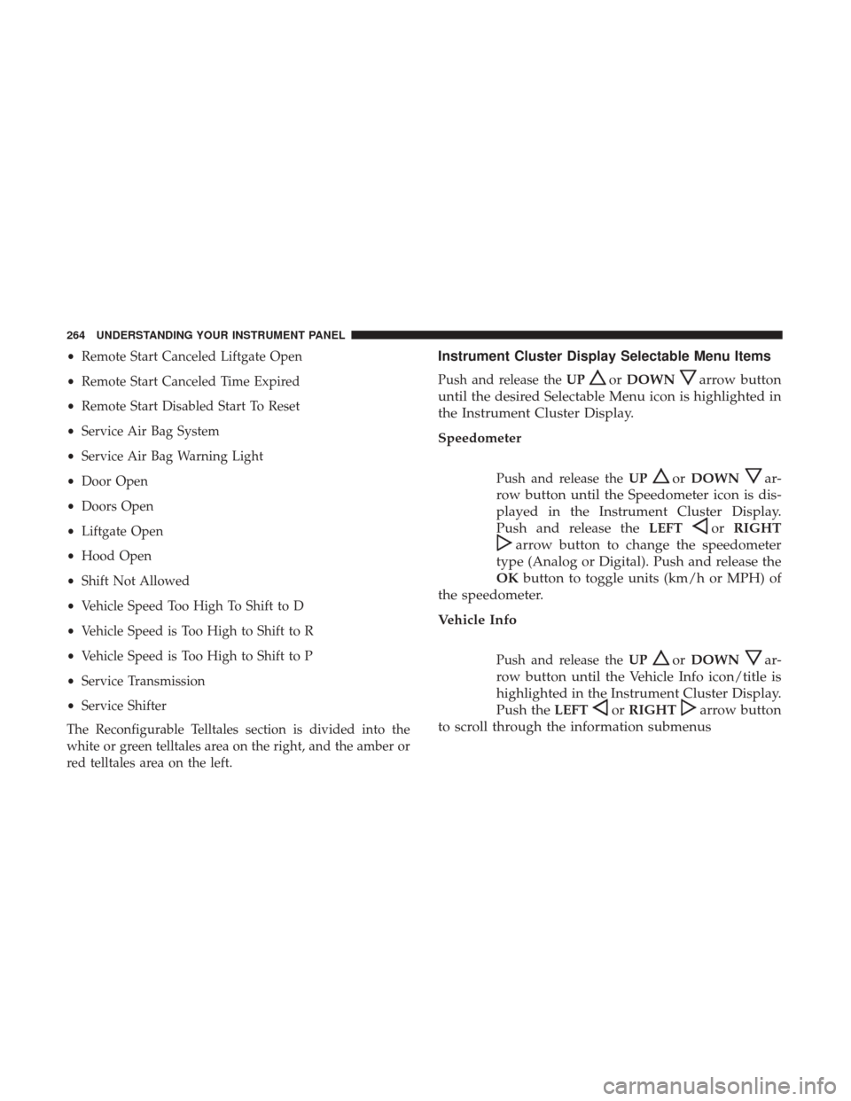
Push and release the UPorDOWNarrow button
until the desired Selectable Menu icon is highlighted in
the Instrument Cluster Display.
Speedometer
Push and release the UPorDOWNar-
row button until the Speedometer icon is dis-
played in the Instrument Cluster Display.
Push and release the LEFT
orRIGHT
arrow button to change the speedometer
type (Analog or Digital). Push and release the
OK button to toggle units (km/h or MPH) of
the speedometer.
Vehicle Info
Push and release the UPorDOWNar-
row button until the Vehicle Info icon/title is
highlighted in the Instrument Cluster Display.
Push the LEFT
orRIGHTarrow button
to scroll through the information submenus
264 UNDERSTANDING YOUR INSTRUMENT PANEL
Page 267 of 584
Tire Pressure Monitor System
•If tire pressure is OKfor all tires a vehicle ICON is
displayed with tire pressure values in each corner of the
ICON.
• If one or more tires have low pressure, “Inflate Tire To
XX” is displayed with the vehicle ICON and the tire
pressure values in each corner of the ICON with the
pressure value of the low tire are displayed in a different
color than the other tire pressure value.
• If the Tire Pressure system requires service, “Service Tire
Pressure System” is displayed.
Tire PSI is an information only function, and cannot be
reset.
Refer to “Tire Pressure Monitoring System (TPMS)” under
“Starting and Operating” for further information. Transmission Temperature
•
Displays the actual transmission temperature.
Oil Temperature
• Displays the actual oil temperature.
4
UNDERSTANDING YOUR INSTRUMENT PANEL 265
Page 268 of 584
Oil Pressure
•Displays the actual oil pressure.
Oil Life
Battery Voltage
Driver Assist — If Equipped
Push and release the UPorDOWNar-
row button until the Driver Assist display
icon/title is highlighted in the Instrument
Cluster Display. For further information, refer
to “Adaptive Cruise Control (ACC) — If Equipped” in
“Understanding The Features Of Your Vehicle.”
266 UNDERSTANDING YOUR INSTRUMENT PANEL
Page 269 of 584

Fuel Economy
Push and release theUPorDOWNar-
row button until the Fuel Economy Menu
icon/title is highlighted. Push the LEFTor
RIGHT arrow button to scroll the submenus,
one with current fuel economy display and one without
it.
• Range
• Current MPG or L/100 km or km/l
• Average MPG or L/100 km or km/l
• Press the OKbutton to reset the average fuel economy
NOTE: The Range feature is not able to be reset through
the Instrument Cluster Display Controls.
Trip
Push and release the UPorDOWNar-
row button until the Trip icon/title is high-
lighted in the Instrument Cluster Display, then
push and release the LEFT
orRIGHT
arrow button to select Trip A or Trip B.
The Trip A and Trip B information will display the
following:
•Distance
• Average Fuel Economy
• Elapsed Time
Hold the OKbutton to reset all the information.
Stop/Start — If Equipped
Push and release the UPorDOWNar-
row button until the Stop/Start icon/title is
highlighted in the Instrument Cluster Display.
The screen will display the Stop/Start status.
Audio
Push and release the UPorDOWNar-
row button until the Audio Menu icon/title is
highlighted in the Instrument Cluster Display.
4
UNDERSTANDING YOUR INSTRUMENT PANEL 267
Page 270 of 584

Stored Messages
Push and release theUPorDOWNar-
row button until the Messages Menu item is
highlighted. This feature shows the number of
stored warning messages. Pushing the RIGHT
arrow button will allow you to see what the stored
messages are.
When no messages are present, main menu icon will be a
closed envelope.
Screen Setup
Push and release the UPorDOWNar-
row button until the Screen Setup Menu icon/
title is highlighted in the Instrument Cluster
Display. Push and release the OKbutton to
enter the submenus and follow the prompts on the
screen as needed. The Screen Setup feature allows you
to change what information is displayed in the instru-
ment cluster as well as the location that information is
displayed. Screen Setup Driver Selectable Items
Current Gear
•
On
• Off (default setting)
Favorite Menus
• Speedometer
• Vehicle Info
• Driver Assist (Show/Hide)
• Fuel Economy (Show/Hide)
• Trip (Show/Hide)
• Stop/Start
• Audio (Show/Hide)
• Stored Messages
• Screen Setup
NOTE: Menus with (show/hide) can push the OKbutton
to choose whether to show or hide this menu on the
Instrument Cluster Display.
268 UNDERSTANDING YOUR INSTRUMENT PANEL
Page 271 of 584

Upper Left
•None
• Compass (default setting)
• Outside Temp
• Time
• Range To Empty (RTE)
• Fuel Economy Average
• Fuel Economy Current
• Trip A
• Trip B
Upper Right
• None
• Compass
• Outside Temp (default setting)
• Time
• Range To Empty (RTE)
• Fuel Economy Average •
Fuel Economy Current
• Trip A
• Trip B
Defaults (Restores All Settings To Default Settings)
• Restore
• Cancel
Battery Saver On/Battery Saver Mode Message —
Electrical Load Reduction Actions — If Equipped
This vehicle is equipped with an Intelligent Battery Sensor
(IBS) to perform additional monitoring of the electrical
system and status of the vehicle battery.
In cases when the IBS detects charging system failure, or
the vehicle battery conditions are deteriorating, electrical
load reduction actions will take place to extend the driving
time and distance of the vehicle. This is done by reducing
power to or turning off non-essential electrical loads.
Load reduction is only active when the engine is running.
It will display a message if there is a risk of battery
depletion to the point where the vehicle may stall due to
lack of electrical supply, or will not restart after the current
drive cycle.
4
UNDERSTANDING YOUR INSTRUMENT PANEL 269
Page 272 of 584

When load reduction is activated, the message “Battery
Saver On” or “Battery Saver Mode” will appear in the
Instrument Cluster Display.
These messages indicate the vehicle battery has a low state
of charge and continues to lose electrical charge at a rate
that the charging system cannot sustain.
NOTE:
•The charging system is independent from load reduc-
tion. The charging system performs a diagnostic on the
charging system continuously.
• If the Battery Charge Warning Light is on it may indicate
a problem with the charging system. Refer to “Battery
Charge Warning Light” in “Understanding Your Instru-
ment Panel” for further information.
The electrical loads that may be switched off (if equipped),
and vehicle functions which can be effected by load reduction:
• Heated Seat/Vented Seats/Heated Wheel
• Heated/Cooled Cup Holders — If Equipped
• Rear Defroster And Heated Mirrors
• HVAC System •
115V AC Power Inverter System
• Audio and Telematics System
Loss of the battery charge may indicate one or more of the
following conditions:
• The charging system cannot deliver enough electrical
power to the vehicle system because the electrical loads
are larger than the capability of charging system. The
charging system is still functioning properly.
• Turning on all possible vehicle electrical loads (e.g.
HVAC to max settings, exterior and interior lights,
overloaded power outlets +12V, 115V AC, USB ports)
during certain driving conditions (city driving, towing,
frequent stopping).
•
Installing options like additional lights, upfitter electrical
accessories, audio systems, alarms and similar devices.
• Unusual driving cycles (short trips separated by long
parking periods).
• The vehicle was parked for an extended period of time
(weeks, months).
• The battery was recently replaced and was not charged
completely.
270 UNDERSTANDING YOUR INSTRUMENT PANEL
Page 276 of 584

change settings (i.e., 30, 60, 90), push the center of the
control knob one or more times to select or change a setting
(i.e., ON, OFF).
Your Uconnect system may also have Screen Off and Back
buttons located below the Uconnect system.
Push the Screen Off button to turn off the Uconnect
touchscreen. Push the Screen Off button a second time to
turn the touchscreen on.
Push the Back button to exit out of a Menu or certain
option on the Uconnect system.
Buttons On The Touchscreen
Buttons on the touchscreen are accessible on the Uconnect
display.
Customer Programmable Features — Uconnect 5.0
Personal Settings
Push the MORE button on the faceplate to display the
menu setting screen. In this mode the Uconnect system
allows you to access programmable features that may be
equipped such as Display, Voice, Clock & Date, Safety &Assistance, Lights, Doors & Locks, Auto-On Comfort,
Engine Off Options, Compass Settings, Audio, Phone/
Bluetooth, Sirius Setup, Restore Settings, Clear Personal
Data, and System Information.
NOTE:
Only one touchscreen area may be selected at a
time.
When making a selection, press the button on the touch-
screen to enter the desired mode. Once in the desired
mode, press and release the preferred setting and make
your selection. Once the setting is complete, either press
the Back Arrow/Done button on the touchscreen or the
Back button on the faceplate to return to the previous menu
or press the “X” button on the touchscreen to close out of
the settings screen. Pressing the “Up” or “Down” Arrow
buttons on the right side of the screen will allow you to
toggle up or down through the available settings.
NOTE: All settings should be changed with the ignition in
the RUN position.
274 UNDERSTANDING YOUR INSTRUMENT PANEL