2017 CHEVROLET COLORADO ignition
[x] Cancel search: ignitionPage 313 of 419

Chevrolet Colorado Owner Manual (GMNA-Localizing-U.S./Canada/Mexico-10122675) - 2017 - crc - 8/22/16
312 Vehicle Care
The vehicle may not be equippedwith all of the fuses, relays, andfeatures shown.
Fuses Usage
F1 Traction controlmodule power
F2 Engine controlmodule power
F3 A/C clutch
F4–
F5 Engine controlmodule/Integratedchassis controlmodule/Fuel pumppower module
F6 Wipers
F7 Cargo lamp/Bedlighting (ifequipped)
F8 Fuel injectors-even
F9 Fuel injectors - odd
F10 Engine controlmodule 1
Fuses Usage
F11 Miscellaneous 1/Ignition
F12 Starter
F13 Traction controlmodule
F14–
F15–
F16–
F17 Front axle actuator
F18–
F19 Aeroshutters
F20–
F21 Front blower
F22 Antilock brakesystem valves
F23–
F24 Trailer
F25 Transfer caseelectronic control
F26 Antilock brakesystem pump
Fuses Usage
F27 Trailer brakecontrol module
F28 Rear windowdefogger
F29–
F30 Driver heated seat
F31–
F32 Passengerheated seat
F33 Body controlmodule 3
F34 Fuel system controlmodule
F35 Integrated chassiscontrol module (ifequipped)
F36 Centerhigh-mountedstoplamp
F37 Right high-beamheadlamp
F38 Left high-beamheadlamp
Page 314 of 419

Chevrolet Colorado Owner Manual (GMNA-Localizing-U.S./Canada/Mexico-10122675) - 2017 - crc - 8/22/16
Vehicle Care 313
FusesUsage
F39–
F40–
F41–
F42–
F43 Cooling fan
F44 Vacuum pump
F45–
F46 Engine controlmodule 2
F47 Miscellaneous 2/Ignition
F48 Fog lamps (ifequipped)
F49–
F50 Trailer parkinglamps
F51 Horn
F52–
F53–
F54–
F55–
FusesUsage
F56 Washer pump
F57–
F58–
F59 Trailer wiring
F60 Mirrors defogger
F61–
F62 Canister ventsolenoid
F63–
F64 Trailerreverse lamp
F65 Left trailerstoplamp/Turnsignal lamps
F66 Right trailerstoplamp/Turnsignal lamps
F67 Electric powersteering
F68–
F69 Battery regulatedvoltage control
F70–
FusesUsage
F71–
F72–
F73–
F74 Generator
F75–
RelaysUsage
K1 A/C clutch
K2 Starter
K3–
K4 Wipers speed
K5 Wipers control
K6 Cargo lamp/Bedlighting (ifequipped)
K7 Powertrain
K8–
K9–
K10–
K11 Centerhigh-mountedstoplamp
Page 317 of 419

Chevrolet Colorado Owner Manual (GMNA-Localizing-U.S./Canada/Mexico-10122675) - 2017 - crc - 8/22/16
316 Vehicle Care
FusesUsage
F22–
F23 Data linkconnector/USB
F24 HVAC ignition
F25 Body control module 7
F26–
F27–
F28 Instrument panel/Sensing anddiagnostic module/Ignition
F29 Miscellaneous/Ignition
F30–
F31 Front camera
F32 Steering wheelcontrols backlighting
F33 Heated steering wheel
F34 Front ventilated seats
F35 Park/Reverse/Neutral/Drive/Low/Wirelesscharging module
F36 Discrete logic ignitionsensor
FusesUsage
F37–
F38–
F39 Auxiliary poweroutlet 2
F40 Auxiliary power outlet
F41 Auxiliary poweroutlet 1/Lighter
F42 Left power window
F43 Driver power seat
F44–
F45 Right power window
F46 Passenger power seat
RelaysUsage
K1 Retained accessorypower
K2 Run/Crank
Wheels and Tires
Tires
Every new GM vehicle has
high-quality tires made by a
leading tire manufacturer. See
the warranty manual for
information regarding the tire
warranty and where to get
service. For additional
information refer to the tire
manufacturer.
{Warning
.Poorly maintained and
improperly used tires are
dangerous.
.Overloading the tires can
cause overheating as a
result of too much
flexing. There could be a
blowout and a serious
crash. SeeVehicle Load
Limits0226.
(Continued)
Page 327 of 419

Chevrolet Colorado Owner Manual (GMNA-Localizing-U.S./Canada/Mexico-10122675) - 2017 - crc - 8/22/16
326 Vehicle Care
Tire Pressure Monitor
Operation
This vehicle may have a TirePressure Monitor System (TPMS).The TPMS is designed to warn thedriver when a low tire pressurecondition exists. TPMS sensors aremounted onto each tire and wheelassembly, excluding the spare tireand wheel assembly. The TPMSsensors monitor the air pressure inthe tires and transmit the tirepressure readings to a receiverlocated in the vehicle.
When a low tire pressure conditionis detected, the TPMS illuminatesthe low tire pressure warning lightlocated on the instrument cluster.If the warning light comes on, stopas soon as possible and inflate thetires to the recommended pressure
shown on the Tire and LoadingInformation label. SeeVehicle LoadLimits0226.
AmessagetocheckthepressureinaspecifictiredisplaysintheDriverInformation Center (DIC). The lowtire pressure warning light and theDIC warning message come on ateach ignition cycle until the tires areinflated to the correct inflationpressure. Using the DIC, tirepressure levels can be viewed. Foradditional information and detailsabout the DIC operation anddisplays, seeDriver InformationCenter (DIC) (Base Level)0126orDriver Information Center (DIC)(Uplevel)0129andTire Messages0137.
The low tire pressure warning lightmay come on in cool weather whenthe vehicle is first started, and thenturn off as the vehicle is driven. Thiscould be an early indicator that theair pressure is getting low andneeds to be inflated to the properpressure.
ATire and Loading Information labelshows the size of the originalequipment tires and the correctinflation pressure for the tires whenthey are cold. SeeVehicle LoadLimits0226,foranexampleoftheTire and Loading Information labeland its location. Also seeTirePressure0323.
The TPMS can warn about a lowtire pressure condition but it doesnot replace normal tiremaintenance. SeeTire Inspection0329,Tire Rotation0329,andTires0316.
Caution
Tire sealant materials are not all
the same. A non-approved tire
sealant could damage the TPMS
sensors. TPMS sensor damage
caused by using an incorrect tire
sealant is not covered by the
vehicle warranty. Always use only
the GM approved tire sealant
available through your dealer or
included in the vehicle.
Page 328 of 419

Chevrolet Colorado Owner Manual (GMNA-Localizing-U.S./Canada/Mexico-10122675) - 2017 - crc - 8/22/16
Vehicle Care 327
TPMS Malfunction Light and
Message
The TPMS will not function properlyif one or more of the TPMS sensorsare missing or inoperable. When thesystem detects a malfunction, thelow tire pressure warning lightflashes for about one minute andthen stays on for the remainder ofthe ignition cycle. A DIC warningmessage also displays. Themalfunction light and DIC warningmessage come on at each ignitioncycle until the problem is corrected.Some of the conditions that cancause these to come on are:
.One of the road tires has beenreplaced with the spare tire. Thespare tire does not have aTPMS sensor. The malfunctionlight and the DIC messageshould go off after the road tireis replaced and the sensormatching process is performedsuccessfully. See“TPMS SensorMatching Process”later in thissection.
.The TPMS sensor matchingprocess was not done or notcompleted successfully afterrotating the tires. Themalfunction light and the DICmessage should go off aftersuccessfully completing thesensor matching process. See“TPMS Sensor MatchingProcess”later in this section.
.One or more TPMS sensors aremissing or damaged. Themalfunction light and the DICmessage should go off when theTPMS sensors are installed andthe sensor matching process isperformed successfully. Seeyour dealer for service.
.Replacement tires or wheels donot match the original equipmenttires or wheels. Tires and wheelsother than those recommendedcould prevent the TPMS fromfunctioning properly. SeeBuyingNew Tires0331.
.Operating electronic devices orbeing near facilities using radiowave frequencies similar to theTPMS could cause the TPMSsensors to malfunction.
If the TPMS is not functioningproperly, it cannot detect or signal alow tire condition. See your dealerfor service if the TPMS malfunctionlight and DIC message come onand stay on.
TPMS Sensor Matching
Process
Each TPMS sensor has a uniqueidentification code. The identificationcode needs to be matched to a newtire/wheel position after rotating thevehicle’stiresorreplacingoneormore of the TPMS sensors. Also,the TPMS sensor matching processshould be performed after replacingasparetirewitharoadtirecontaining the TPMS sensor. Themalfunction light and the DICmessage should go off at the nextignition cycle. The sensors arematched to the tire/wheel positions,using a TPMS relearn tool, in thefollowing order: driver side front tire,
Page 329 of 419

Chevrolet Colorado Owner Manual (GMNA-Localizing-U.S./Canada/Mexico-10122675) - 2017 - crc - 8/22/16
328 Vehicle Care
passenger side front tire, passengerside rear tire, and driver side rear.See your dealer for service or topurchase a relearn tool. A TPMSrelearn tool can also be purchased.See Tire Pressure Monitor SensorActivation Tool atwww.gmtoolsandequipment.com orcall 1-800-GM TOOLS(1-800-468-6657).
There are two minutes to match thefirst tire/wheel position, andfive minutes overall to match all fourtire/wheel positions. If it takeslonger, the matching process stopsand must be restarted.
The TPMS sensor matchingprocess is:
1. Set the parking brake.
2. Turn the ignition to ON/RUNwith the engine off.
3. If the vehicle has an uplevelDIC, make sure the TirePressure info page option isturned on. The info pages onthe DIC can be turned on andoff through the Settings menu.
SeeDriver Information Center(DIC) (Base Level)0126orDriver Information Center (DIC)(Uplevel)0129.
4. If the vehicle has an uplevelDIC, use the DIC controls onthe right side of the steeringwheel to scroll to the TirePressure screen under the DICinfo page.
If the vehicle has a base levelDIC, use the MENU button toselect the Vehicle Informationmenu in the DIC. Use thethumbwheel to scroll to the TirePressure Menu item screen.
5. If the vehicle has an uplevel
DIC, press and holdVin the
center of the DIC controls.
If the vehicle has a base levelDIC, press SET/CLR on theturn signal lever to begin thesensor matching process.
Amessageaskingiftheprocess should begin shouldappear. Press SET/CLR againto confirm the selection.
The horn sounds twice tosignal the receiver is in relearnmode and the TIRELEARNING ACTIVE messagedisplays on the DIC screen.
6. Start with the driver sidefront tire.
7. Place the relearn tool againstthe tire sidewall, near the valvestem. Then press the button toactivate the TPMS sensor.Ahornchirpconfirmsthatthesensor identification code hasbeen matched to this tire andwheel position.
8. Proceed to the passenger sidefront tire, and repeat theprocedure in Step 7.
9. Proceed to the passenger siderear tire, and repeat theprocedure in Step 7.
10. Proceed to the driver side reartire, and repeat the procedurein Step 7. The horn sounds twotimes to indicate the sensoridentification code has beenmatched to the driver side reartire, and the TPMS sensor
Page 340 of 419

Chevrolet Colorado Owner Manual (GMNA-Localizing-U.S./Canada/Mexico-10122675) - 2017 - crc - 8/22/16
Vehicle Care 339
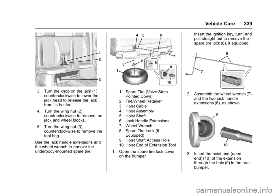
3. Turn the knob on the jack (1)counterclockwise to lower thejack head to release the jackfrom its holder.
4. Turn the wing nut (2)counterclockwise to remove thejack and wheel blocks.
5. Turn the wing nut (3)counterclockwise to remove thetool bag.
Use the jack handle extensions andthe wheel wrench to remove theunderbody-mounted spare tire.
1. Spare Tire (Valve StemPointed Down)
2. Tire/Wheel Retainer
3. Hoist Cable
4. Hoist Assembly
5. Hoist Shaft
6. Jack Handle Extensions
7. Wheel Wrench
8. Spare Tire Lock (IfEquipped)
9. Hoist Shaft Access Hole
10. Hoist End of Extension Tool
1. Open the spare tire lock coveron the bumper.
Insert the ignition key, turn, andpull straight out to remove thespare tire lock (8), if equipped.
2. Assemble the wheel wrench (7)and the two jack handleextensions (6), as shown.
3. Insert the hoist end (openend) (10) of the extensionthrough the hole (9) in the rearbumper.
Page 351 of 419

Chevrolet Colorado Owner Manual (GMNA-Localizing-U.S./Canada/Mexico-10122675) - 2017 - crc - 8/22/16
350 Vehicle Care
4. Turn the ignition to LOCK/OFF.Turn off all lights andaccessories in both vehicles,except the hazard warningflashers if needed.
{Warning
An electric fan can start up even
when the engine is not running
and can injure you. Keep hands,
clothing, and tools away from any
underhood electric fan.
{Warning
Using a match near a battery can
cause battery gas to explode.
People have been hurt doing this,
and some have been blinded.
Use a flashlight if you need more
light.
Battery fluid contains acid that
can burn you. Do not get it on
you. If you accidentally get it in
(Continued)
Warning (Continued)
your eyes or on your skin, flush
the place with water and get
medical help immediately.
{Warning
Fans or other moving engine
parts can injure you badly. Keep
your hands away from moving
parts once the engine is running.
5. Connect one end of the redpositive (+) cable to thepositive (+) terminal on thedischarged battery.
6. Connect the other end of thered positive (+) cable to thepositive (+) terminal of the goodbattery.
7. Connect one end of the blacknegative (–)cabletothenegative (–)terminalofthegood battery.
8. Connect the other end of theblack negative (–)cabletothenegative (–)groundingstudforthe discharged battery.
9. Start the engine in the vehiclewith the good battery and runthe engine at idle speed for atleast four minutes.
10. Try to start the vehicle that hadthe dead battery. If it will notstart after a few tries, itprobably needs service.
Caution
If the jumper cables are
connected or removed in the
wrong order, electrical shorting
may occur and damage the
vehicle. The repairs would not be
covered by the vehicle warranty.
Always connect and remove the
jumper cables in the correct order,
making sure that the cables do
not touch each other or other
metal.