2017 Alfa Romeo Giulia wheel
[x] Cancel search: wheelPage 146 of 268
Steering Wheel Shift Paddles — If
Equipped
The gear can be manually shifted also
by using the paddles behind the
steering wheel, pull the right paddle (+)
towards the steering wheel and release
it to engage a higher gear, perform the
same operation with the left paddle (-)
to engage a lower gear.
Note:
If only one manual shift is necessary,
the letter (D) will remain on the display
with the engaged gear next to it.
Deactivation
To deactivate the sequential driving
mode, bring the gear selector back in
position DRIVE (D) ("automatic" driving
mode).
Warning!
Do not downshift for additional engine
braking on a slippery surface. The drive
wheels could lose their grip and the vehicle
could skid, causing a collision or personal
injury.
Note:To select the correct gear for
maximum deceleration (engine brake),
just keep the gear paddle pulled (–):
the transmission goes to an operating
mode in which the vehicle can slow
down easily.
The vehicle will keep the gear
selected by the driver until the safety
conditions allow it.
This means, for example, that the
system will try to prevent the engine
from switching off, automatically
downshifting if the engine speed is too
low.
Automatic Transmission
Limp Home Mode
Transmission function is monitored
electronically for abnormal conditions. If
a condition is detected that could result
in transmission damage, Transmission
Limp Home Mode is activated. In this condition, the transmission stays
in fourth gear, regardless of the selected
gear. Positions PARK (P), REVERSE (R)
and NEUTRAL (N) still work.
The
symbol might light up in the
instrument cluster.
Temporary failure
In the event of a momentary problem,
the transmission can be reset to regain
all forward gears by performing the
following steps:
1. Stop the vehicle.
2. Shift the transmission into PARK (P),
if possible. If not, shift the transmission
to NEUTRAL (N).
3. Push and hold the ignition until the
engine turns OFF.
4. Wait for about 10 seconds, then
restart the engine.
5. Shift into the desired gear range. If
the problem is no longer detected, the
transmission will return to normal
operation.
Note: Even if the transmission can be
reset, we recommend that you visit your
authorized dealer at your earliest
possible convenience. Your authorized
dealer has diagnostic equipment to
determine if the problem could reoccur.
If the transmission cannot be reset,
service is required at your authorized
dealer.
07076S0006EMSteering Wheel Shift Paddles
144
STARTING AND OPERATING
Page 153 of 268
System Manual
Activation/Deactivation
To manually activate/deactivate the
system, push the button located in the
control panel on the left of the steering
wheel.
System Activation
The activation of the system is indicated
by the
symbol lighting up on the
display. In this condition, the light on the
buttonisoff.
System Deactivation
A message will appear on the display
when the system is deactivated. In this
condition, the light on the button is on.
Note: Each time the engine is started,
the system is activated regardless of
where was when it was previously
switched off.
Possible Reasons The
Engine Does Not
Autostop
For higher comfort and increased
safety, and to reduce emissions, there
are certain conditions where the engine
will not stop despite the system being
active, such as:
Engine still cold.
Especially cold outside temperature.
Battery not sufficiently charged.
Driver's door not shut.
Driver's seat belt not fastened.
Reverse gear engaged (e.g. for
parking maneuvers).
With the automatic climate control
active, an adequate cabin heating or
cooling comfort has not been reached
or with MAX-DEF function active.
During the first period of use, to
initialize the system.
Steering angle beyond threshold.
Engine Restarting
Conditions
Due to comfort, emission control and
safety reasons, the engine can restart
automatically without any action by the
driver, under special conditions, such
as:
Battery not sufficiently charged.
Reduced braking system vacuum
(e.g. if the brake pedal is pressed
repeatedly).
Vehicle moving (e.g. when driving on
roads with a grade).
Engine stopping by the Stop/Start
Evo system for more than approx. three
minutes.
With the automatic climate control
active, an adjustment in cabin heating
or cooling is made or with MAX-DEF
function active.
Safety Functions
When the engine is stopped through
the Stop/Start Evo system, if the driver
releases their seat belt, opens the
driver's or passenger's door, or opens
the hood from inside the vehicle, the
engine can be restarted only by using
the ignition.
This condition is indicated to the driver
both through a buzzer and a message
on the instrument cluster display.
Irregular Operation
In the event of malfunction, the
Stop/Start Evo system is deactivated.
For failure indications, see the "Warning
Lights and Messages" paragraph,
"Getting To Know Your Instrument
Panel" chapter.
Vehicle Inactivity
In the event of vehicle inactivity (or if the
battery is replaced), special attention
must be paid to the disconnection of
the battery power supply.
07126S0051EMStop/Start Evo Button
151
Page 155 of 268
EXCEEDING THE
PROGRAMMED SPEED
By fully depressing the accelerator
pedal, the programmed speed can be
exceeded even with the device active
(e.g. in the event of overtaking).
The device is disabled until the speed
drops below the set limit, after which it
reactivates automatically.
PROGRAMMED SPEED
ICON FLASHING
The programmed speed flashes in the
following cases:
when the accelerator pedal has been
fully depressed and the vehicle has
exceeded the programmed speed;
activating the system after setting a
limit below the effective speed of the
vehicle;
in the event of sharp acceleration.
DEACTIVATING THE
DEVICE
The function can be activated/
deactivated on the Connect system.
Deactivating the device
To access the function, on the main
menu select the following items in
sequence: "Settings", "Safety", “Speed
Limiter” and “off”.
Automatic deactivation of the
device
The device deactivates automatically in
the event of fault in the system. In this
case, contact an authorized dealer.
Temporary signal loss
When the devices loses the signal, the
white symbol without the speed
indication lights up on the display.
System failure
When the system is in failure, the amber
symbol
lights up on the display.
ELECTRONIC SPEED
CONTROL
Electronic Speed
Control Description
This is an electronically controlled
driving assistance feature that allows
the desired vehicle speed to be
maintained, without having to press the
accelerator pedal. This feature can be
used at a speed above 25 mph
(40 km/h) on long stretches of dry,
straight roads with few variations
(highways).
It is not recommended to use this
feature in city traffic.
The speed control buttons are located
on the left side of the steering wheel.
Note: To ensure correct operation, the
speed control is designed to deactivate
if more than one function is operated
simultaneously. In this case, the system
can be reactivated by pushing the
on/off button
and setting the
desired speed.
While driving downhill, the system could
brake the vehicle to keep the set speed
the same.
153
Page 156 of 268
Warning!
Speed Control can be dangerous where
the system cannot maintain a constant
speed. Your vehicle could go too fast for
the conditions, and you could lose control
and have an accident. Do not use Speed
Control in heavy traffic or on roads that are
winding, icy, snow-covered or slippery.
Activating
To activate the Electronic Speed
Control System, push the on/off button
location on the left side of the steering
wheel.
The activation of the system is signaled
by the white warning light
switching
on the instrument cluster. The Electronic Speed Control function
can remain active at the same time as
the Speed Limiter System. If a speed
limit below the one indicated in the set
speed control, the speed control speed
will be lowered to that of the Speed
Limiter.
This function remains available in RACE
mode.
Note:
The system cannot be engaged
in FIRST or REVERSE gear. It is
advisable to engage it in THIRD gear or
higher if using the Autostick feature.
Warning!
Leaving the Speed Control system on
when not in use is dangerous. You could
accidentally set the system or cause it to
go faster than you want. You could lose
control and have an accident. Always leave
the system OFF when you are not using it.
Setting The Desired
Speed
To set a desired speed, proceed as
follows:
1. Turn the Electronic Speed Control
on. 2. When the vehicle has reached the
desired speed, push the SET switch up
or down and release to activate. When
the accelerator is released, the vehicle
will keep the selected speed
automatically.
If needed (when overtaking for
instance), you can accelerate simply by
pressing the accelerator; when you
release the pedal, the vehicle goes
back to the previously set speed.
When traveling downhill with the system
active, the vehicle speed may slightly
exceed the set one.
Note:
Before pushing the SET switch,
the vehicle must be traveling at a
constant speed on a flat surface.
07146S0001EMElectronic Speed Control On/Off Switch
07146S0002EMSet Switch Location
154
STARTING AND OPERATING
Page 159 of 268
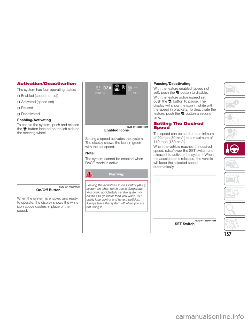
Activation/Deactivation
The system has four operating states:
Enabled (speed not set)
Activated (speed set)
Paused
Deactivated
Enabling/Activating
To enable the system, push and release
the
button located on the left side on
the steering wheel.
When the system is enabled and ready
to operate, the display shows the white
icon above dashes in place of the
speed. Setting a speed activates the system.
The display shows the icon in green
with the set speed.
Note:
The system cannot be enabled when
RACE mode is active.
Warning!
Leaving the Adaptive Cruise Control (ACC)
system on when not in use is dangerous.
You could accidentally set the system or
cause it to go faster than you want. You
could lose control and have a collision.
Always leave the system off when you are
not using it.
Pausing/Deactivating
With the feature enabled (speed not
set), push the
button to disable.
With the feature active (speed set),
push the
button to pause. The
display will show the icon in white with
the speed in brackets. To deactivate the
feature, push the
button a second
time.
Setting The Desired
Speed
The speed can be set from a minimum
of 20 mph (30 km/h) to a maximum of
110 mph (180 km/h).
When the vehicle reaches the desired
speed, raise/lower the SET switch and
release it to activate the system. When
the accelerator is released, the vehicle
will keep the selected speed
automatically.
GUID-07146S0010EMOn/Off Button
GUID-07146S0016EMEnabled Icons
GUID-07146S0017EMSET Switch
157
Page 173 of 268
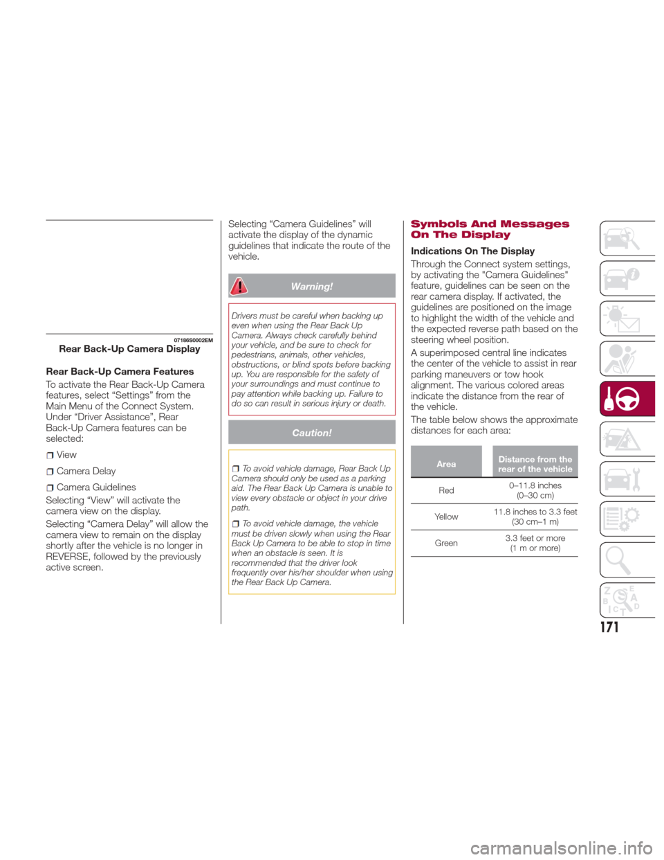
Rear Back-Up Camera Features
To activate the Rear Back-Up Camera
features, select “Settings” from the
Main Menu of the Connect System.
Under “Driver Assistance”, Rear
Back-Up Camera features can be
selected:
View
Camera Delay
Camera Guidelines
Selecting “View” will activate the
camera view on the display.
Selecting “Camera Delay” will allow the
camera view to remain on the display
shortly after the vehicle is no longer in
REVERSE, followed by the previously
active screen. Selecting “Camera Guidelines” will
activate the display of the dynamic
guidelines that indicate the route of the
vehicle.
Warning!
Drivers must be careful when backing up
even when using the Rear Back Up
Camera. Always check carefully behind
your vehicle, and be sure to check for
pedestrians, animals, other vehicles,
obstructions, or blind spots before backing
up. You are responsible for the safety of
your surroundings and must continue to
pay attention while backing up. Failure to
do so can result in serious injury or death.
Caution!
To avoid vehicle damage, Rear Back Up
Camera should only be used as a parking
aid. The Rear Back Up Camera is unable to
view every obstacle or object in your drive
path.
To avoid vehicle damage, the vehicle
must be driven slowly when using the Rear
Back Up Camera to be able to stop in time
when an obstacle is seen. It is
recommended that the driver look
frequently over his/her shoulder when using
the Rear Back Up Camera.
Symbols And Messages
On The Display
Indications On The Display
Through the Connect system settings,
by activating the "Camera Guidelines"
feature, guidelines can be seen on the
rear camera display. If activated, the
guidelines are positioned on the image
to highlight the width of the vehicle and
the expected reverse path based on the
steering wheel position.
A superimposed central line indicates
the center of the vehicle to assist in rear
parking maneuvers or tow hook
alignment. The various colored areas
indicate the distance from the rear of
the vehicle.
The table below shows the approximate
distances for each area:
Area Distance from the
rear of the vehicle
Red 0–11.8
inches
(0–30 cm)
Yellow 11.8 inches to 3.3 feet
(30 cm–1 m)
Green 3.3 feet or more
(1mormore)
07186S0002EMRear Back-Up Camera Display
171
Page 176 of 268
Payload
The payload of a vehicle is defined as
the allowable load weight a truck can
carry, including the weight of the driver,
all passengers, options and cargo.
Gross Axle Weight Rating
(GAWR)
The GAWR is the maximum permissible
load on the front and rear axles. The
load must be distributed in the cargo
area so that the GAWR of each axle is
not exceeded.
Each axle GAWR is determined by the
components in the system with the
lowest load carrying capacity (axle,
springs, tires or wheels). Heavier axles
or suspension components sometimes
specified by purchasers for increased
durability does not necessarily increase
the vehicle's GVWR.
Tire Size
The tire size on the Vehicle Certification
Label represents the actual tire size on
your vehicle. Replacement tires must be
equal to the load capacity of this tire
size.
Rim Size
This is the rim size that is appropriate
for the tire size listed.
Inflation Pressure
This is the cold tire inflation pressure for
your vehicle for all loading conditions up
to full GAWR.
Curb Weight
The curb weight of a vehicle is defined
as the total weight of the vehicle with all
fluids, including vehicle fuel, at full
capacity conditions, and with no
occupants or cargo loaded into the
vehicle. The front and rear curb weight
values are determined by weighing your
vehicle on a commercial scale before
any occupants or cargo are added.
Loading
The actual total weight and the weight
of the front and rear of your vehicle at
the ground can best be determined by
weighing it when it is loaded and ready
for operation.The entire vehicle should first be
weighed on a commercial scale to
insure that the GVWR has not been
exceeded. The weight on the front and
rear of the vehicle should then be
determined separately to be sure that
the load is properly distributed over the
front and rear axle. Weighing the vehicle
may show that the GAWR of either the
front or rear axles has been exceeded
but the total load is within the specified
GVWR. If so, weight must be shifted
from front to rear or rear to front as
appropriate until the specified weight
limitations are met. Store the heavier
items down low and be sure that the
weight is distributed equally. Stow all
loose items securely before driving.
Improper weight distributions can have
an adverse effect on the way your
vehicle steers and handles and the way
the brakes operate.
Caution!
Do not load your vehicle any heavier than
the GVWR or the maximum front and rear
GAWR. If you do, parts on your vehicle can
break, or it can change the way your
vehicle handles. This could cause you to
lose control. Also overloading can shorten
the life of your vehicle.
174
STARTING AND OPERATING
Page 179 of 268

broken, damaged, worn or have moved
from their correct fitting position. If any
of these things occur, contact your
authorized dealer.
Open welding or loose connections
may permit exhaust gas to enter the
passenger compartment.
Check the exhaust system each time
the vehicle is raised for lubrication or oil
change operations. Replace the
components if necessary, contact your
authorized dealer.
Performance
This vehicle is equipped with an engine
capable of delivering exceptionally fast
acceleration and speed:
Peak power: 505 HP at 6500 rpm.
Peak torque: 443 ft-lbs at
2500–5000 rpm.
Top speed: 190 mph (307 km/h).
Acceleration from 0 to 60 mph (0 to
100 km/h): 3.9 seconds.
For safe driving, it is essential,
particularly during the first days of use,
to get to know the car by driving
carefully and gradually discovering its
performance.
Brakes
The car braking system may be
available with four carbon-ceramic
material brake discs, one on each
wheel. In order to guarantee the maximum
braking capacity for the first use, Alfa
Romeo performs a "run-in" procedure
for discs and pads directly at the
factory.
The use of carbon-ceramic material
brake discs guarantees braking features
(better deceleration/pedal load ratio,
braking distances, fading resistance)
proportional to the dynamic features of
the car in addition to considerably
decreasing the unsprung component
weight.
The materials used and the structural
features of the system could generate
unusual noises which have absolutely
no adverse effect on correct operation
and reliability of the braking system.
Greater pressure may need to be
applied to the brake pedal the first time
to keep the same braking capacities in
presence of condensation or salt on the
braking surfaces, for example after
washing or if the car is not used for a
long time.
Note:
Given the high technological
level of this system, any servicing on it
must be performed by your authorized
dealer which exclusively has the skills
needed for the repair operations. In case of intensive, high-performance
use of the car, have the efficiency of the
carbon-ceramic material braking
system inspected as shown on the
Maintenance Plan at your authorized
dealer.
Driving On Race Tracks
Before driving on a track using a racing
style, it is necessary to:
Attend a race track driving course.
Check the liquid levels in the engine
compartment. For more information,
see the “Checking Levels” section in
the “Servicing And Maintenance”
chapter.
Have the car inspected at your
authorized dealer.
Remember that the car was not
designed to be driven exclusive on the
race track and that this use increases
stress and component wear.
177