2017 Alfa Romeo Giulia change wheel
[x] Cancel search: change wheelPage 5 of 268

VEHICLE CHANGES / ALTERATIONS
Accessories Purchased By The Owner
Warning!
Any change or alteration of the vehicle might seriously affect its safety and road handling, thus causing accidents, in which the occupants
could even be fatally injured.
If you decide to install electrical accessories that require a permanent electrical supply (e.g. radio, satellite anti-theft system,
etc.) or accessories that in any case drain the electrical supply after purchasing the vehicle, contact your authorized dealer.
Dealer personnel will check whether the vehicles's electrical system is able to withstand the load required or whether it needs
to be integrated with a more powerful battery.
Note:
Take care when adding additional spoilers, alloy wheel rims, or non-standard wheel hubs: they could reduce the ventilation of
the brakes and affect efficiency under sharp and repeated braking, or on long descents. Make sure that nothing obstructs the
pedal stroke (mats, etc.).
FCA US LLC shall not be liable for damage caused by the installation of accessories either not supplied or recommended by
FCA US LLC and/or not installed in compliance with the provided instructions.
Installing Electrical/Electronic Devices
Electrical and electronic devices installed after the car is purchased must carry the following label:
FCA US LLC authorizes the installation of transceivers provided that installation is carried out at a specialized center, in
compliance with manufacturer's specifications.
Note:
Local authorities may not allow the vehicle on the road if devices that modify the features of the vehicle have been installed. This
also may void the warranty in relation to faults caused by the change either directly or indirectly related to it.
FCA US LLC shall not be liable for damage caused by the installation of accessories either not supplied or recommended by
FCA US LLC and/or not installed in compliance with the provided instructions.
Page 38 of 268

The high beam headlights are turned off
by pushing the left stalk toward the
instrument panel again. The warning
light/icon
will switch off in the
instrument panel when the headlights
are successfully turned off.
Flashing The Headlights
Pulling the left stalk toward the steering
wheel will activate the high beam
headlights manually. The lights will
remain on as long as the stalk is pulled
back; once the stalk is released, the
lights will switch off again.
Automatic High Beam Headlights —
If Equipped
The Automatic High Beam Headlights
system provides increased forward
lighting at night by automating high
beam control through the use of a
digital camera mounted on the
windshield. This camera detects vehicle
specific light and automatically switches
from high beams to low beams until the
approaching vehicle is out of view.
This function is enabled with the
Connect system, and can only be
activated with the light switch turned to
(AUTO).
If the high beam headlights are on, the
blue icon/warning light
will illuminate
in the instrument panel.
When the speed is higher than 37 mph
(60 km/h) and the function is active, the
lights will switch off if the left stalk is
pushed again. When the speed is lower than 15 mph
(25 km/h) and the function is active, the
function switches the high beam
headlights off.
If the high beam headlights are
operated quickly again (pushing the left
stalk towards the instrument panel), the
warning light/icon
will switch on in
the instrument panel and the main
beam headlights will be switched on
constantly until the speed exceeds
37 mph (60 km/h).
When the speed of 37 mph (60 km/h) is
exceeded again, the automatic
functioning is reactivated.
If the left stalk is pushed again with the
Automatic High Beam Headlights
activated, the Automatic High Beam
Headlights function deactivates.
To deactivate the automatic headlight
function, rotate the headlight switch to
the
position.
Note: If the system recognizes inner
city travel, the automatic functions
remain disabled independently of the
vehicle’s speed.
Turn Signals
To activate the turn signals function,
move the left lever up or down until it
reaches the detent. Moving the lever
upward flashes the right turn signal and
moving the lever downward will flash
the left turn signal. The
orturn signal will blink on the
instrument panel.
The turn signals turn off automatically
when the vehicle is brought back onto a
straight course.
“Lane Change” Function
Tap the lever up or down once, without
moving beyond the detent, and the turn
signal (right or left) will flash five times.
Then, the turn signal (right or left) will
automatically turn off.
To turn off the flashing before the end of
the cycle, move the lever in the
opposite direction until the first click
(about half way).
Static Bending Light
Function (SBL) — If
Equipped
The SBL function utilizes Light Emitting
Diodes (LEDs) in order to better
illuminate the street and increase the
light angle while turning. This function is
enabled by rotating the light switch to
position
or(AUTO). The SBL
LEDs activate when the speed is below
25 mph (40 km/h).
This function can be activated/
deactivated on the Connect system by
selecting the following functions in
sequence on the main menu:
“Settings”, “Lights” and “Cornering
Lights”.
36
GETTING TO KNOW YOUR VEHICLE
Page 99 of 268

and environmental conditions are such
that they wouldn't cause the tires to
slip. When the road and environmental
conditions require better traction, the
vehicle automatically goes to AWD
mode.
The driving mode, RWD or AWD, is
shown on the instrument cluster
display.
Note:If the system failure symbol
switches on, after starting the engine or
while driving, it means that the AWD
system is not working properly. If the
warning message activates frequently, it
is recommended to carry out the
maintenance operations.
Electronic Stability
Control (ESC) System
The ESC system improves the
directional control and stability of the
car in various driving conditions.
The ESC system corrects the car’s
understeer and oversteer, distributing
the brake force on the appropriate
wheels. The torque supplied by the
engine can also be reduced in order to
maintain control of the vehicle.
The ESC system uses sensors installed
on the car to determine the path that
the driver intends to follow and
compares it with the car’s effective
path. When the real path deviates from
the desired path, the ESC system
intervenes to counter the vehicle’s
understeer or oversteer.
Oversteer occurs when the car is
turning more than it should according
to the angle of the steering wheel.
Understeer occurs when the vehicle
is turning less than it should according
to the angle of the steering wheel.
System Intervention
The intervention of the system is
indicated by the flashing of the ESC
warning light on the instrument panel,
to inform the driver that the vehicle
stability and grip are critical.
Warning!
Electronic Stability Control (ESC) cannot
prevent the natural laws of physics from
acting on the vehicle, nor can it increase
the traction afforded by prevailing road
conditions. ESC cannot prevent accidents,
including those resulting from excessive
speed in turns, driving on very slippery
surfaces, or hydroplaning. ESC also cannot
prevent accidents resulting from loss of
vehicle control due to inappropriate driver
input for the conditions. Only a safe,
attentive, and skillful driver can prevent
accidents. The capabilities of an ESC
equipped vehicle must never be exploited
in a reckless or dangerous manner which
could jeopardize the user’s safety or the
safety of others.
Vehicle modifications, or failure to
properly maintain your vehicle, may change
the handling characteristics of your vehicle,
and may negatively affect the performance
of the ESC system. Changes to the
steering system, suspension, braking
system, tire type and size or wheel size
may adversely affect ESC performance.
Improperly inflated and unevenly worn tires
may also degrade ESC performance. Any
vehicle modification or poor vehicle
maintenance that reduces the effectiveness
of the ESC system can increase the risk of
loss of vehicle control, vehicle rollover,
personal injury and death.
Traction Control System
(TCS)
The system automatically operates in
the event of slipping, loss of grip on wet
roads (hydroplaning), and acceleration
on one or both drive wheels on roads
that are slippery, snowy, icy, etc.
Depending on the slipping conditions,
two different control systems are
activated:
If the slipping involves both drive
wheels, the system intervenes, reducing
the power transmitted by the engine.
If the slipping only involves one of the
drive wheels, the Brake Limited
Differential (BLD) function is activated,
automatically braking the wheel which
is slipping (the behavior of a self-locking
differential is simulated). This will
increase the engine torque transferred
to the wheel which isn't slipping.
97
Page 176 of 268

Payload
The payload of a vehicle is defined as
the allowable load weight a truck can
carry, including the weight of the driver,
all passengers, options and cargo.
Gross Axle Weight Rating
(GAWR)
The GAWR is the maximum permissible
load on the front and rear axles. The
load must be distributed in the cargo
area so that the GAWR of each axle is
not exceeded.
Each axle GAWR is determined by the
components in the system with the
lowest load carrying capacity (axle,
springs, tires or wheels). Heavier axles
or suspension components sometimes
specified by purchasers for increased
durability does not necessarily increase
the vehicle's GVWR.
Tire Size
The tire size on the Vehicle Certification
Label represents the actual tire size on
your vehicle. Replacement tires must be
equal to the load capacity of this tire
size.
Rim Size
This is the rim size that is appropriate
for the tire size listed.
Inflation Pressure
This is the cold tire inflation pressure for
your vehicle for all loading conditions up
to full GAWR.
Curb Weight
The curb weight of a vehicle is defined
as the total weight of the vehicle with all
fluids, including vehicle fuel, at full
capacity conditions, and with no
occupants or cargo loaded into the
vehicle. The front and rear curb weight
values are determined by weighing your
vehicle on a commercial scale before
any occupants or cargo are added.
Loading
The actual total weight and the weight
of the front and rear of your vehicle at
the ground can best be determined by
weighing it when it is loaded and ready
for operation.The entire vehicle should first be
weighed on a commercial scale to
insure that the GVWR has not been
exceeded. The weight on the front and
rear of the vehicle should then be
determined separately to be sure that
the load is properly distributed over the
front and rear axle. Weighing the vehicle
may show that the GAWR of either the
front or rear axles has been exceeded
but the total load is within the specified
GVWR. If so, weight must be shifted
from front to rear or rear to front as
appropriate until the specified weight
limitations are met. Store the heavier
items down low and be sure that the
weight is distributed equally. Stow all
loose items securely before driving.
Improper weight distributions can have
an adverse effect on the way your
vehicle steers and handles and the way
the brakes operate.
Caution!
Do not load your vehicle any heavier than
the GVWR or the maximum front and rear
GAWR. If you do, parts on your vehicle can
break, or it can change the way your
vehicle handles. This could cause you to
lose control. Also overloading can shorten
the life of your vehicle.
174
STARTING AND OPERATING
Page 179 of 268

broken, damaged, worn or have moved
from their correct fitting position. If any
of these things occur, contact your
authorized dealer.
Open welding or loose connections
may permit exhaust gas to enter the
passenger compartment.
Check the exhaust system each time
the vehicle is raised for lubrication or oil
change operations. Replace the
components if necessary, contact your
authorized dealer.
Performance
This vehicle is equipped with an engine
capable of delivering exceptionally fast
acceleration and speed:
Peak power: 505 HP at 6500 rpm.
Peak torque: 443 ft-lbs at
2500–5000 rpm.
Top speed: 190 mph (307 km/h).
Acceleration from 0 to 60 mph (0 to
100 km/h): 3.9 seconds.
For safe driving, it is essential,
particularly during the first days of use,
to get to know the car by driving
carefully and gradually discovering its
performance.
Brakes
The car braking system may be
available with four carbon-ceramic
material brake discs, one on each
wheel. In order to guarantee the maximum
braking capacity for the first use, Alfa
Romeo performs a "run-in" procedure
for discs and pads directly at the
factory.
The use of carbon-ceramic material
brake discs guarantees braking features
(better deceleration/pedal load ratio,
braking distances, fading resistance)
proportional to the dynamic features of
the car in addition to considerably
decreasing the unsprung component
weight.
The materials used and the structural
features of the system could generate
unusual noises which have absolutely
no adverse effect on correct operation
and reliability of the braking system.
Greater pressure may need to be
applied to the brake pedal the first time
to keep the same braking capacities in
presence of condensation or salt on the
braking surfaces, for example after
washing or if the car is not used for a
long time.
Note:
Given the high technological
level of this system, any servicing on it
must be performed by your authorized
dealer which exclusively has the skills
needed for the repair operations. In case of intensive, high-performance
use of the car, have the efficiency of the
carbon-ceramic material braking
system inspected as shown on the
Maintenance Plan at your authorized
dealer.
Driving On Race Tracks
Before driving on a track using a racing
style, it is necessary to:
Attend a race track driving course.
Check the liquid levels in the engine
compartment. For more information,
see the “Checking Levels” section in
the “Servicing And Maintenance”
chapter.
Have the car inspected at your
authorized dealer.
Remember that the car was not
designed to be driven exclusive on the
race track and that this use increases
stress and component wear.
177
Page 195 of 268

Inflation Procedure
Warning!
Do not attempt to seal a tire on the side
of the vehicle closest to traffic. Pull far
enough off the road to avoid the danger of
being hit when using the Tire Service Kit.
Do not use Tire Service Kit or drive the
vehicle under the following circumstances:
If the puncture in the tire tread is
approximately 1/4 inch (6 mm) or larger.
If the tire has any sidewall damage.
If the tire has any damage from driving
with extremely low tire pressure.
If the tire has any damage from driving
on a flat tire.
If the wheel has any damage.
If you are unsure of the condition of the
tire or the wheel.
Keep Tire Service Kit away from open
flames or heat sources.
A loose Tire Service Kit thrown forward
in a collision or hard stop could endanger
the occupants of the vehicle. Always stow
the Tire Service Kit in the place provided.
Failure to follow these warnings can result
in injuries that are serious or fatal to you,
your passengers, and others around you.
Take care not to allow the contents of
Tire Service Kit to come in contact with
hair, eyes, or clothing. Tire Service Kit
sealant is harmful if inhaled, swallowed, or
absorbed through the skin. It causes skin,
eye, and respiratory irritation. Flush
immediately with plenty of water if there is
any contact with eyes or skin. Change
clothing as soon as possible, if there is any
contact with clothing.
Tire Service Kit Sealant solution contains
latex. In case of an allergic reaction or rash,
consult a physician immediately. Keep Tire
Service Kit out of reach of children. If
swallowed, rinse mouth immediately with
plenty of water and drink plenty of water.
Do not induce vomiting! Consult a
physician immediately.
To use your Tire Repair Kit, proceed as
follows:
1. Engage the electric parking brake.
2. Insert the sealant cartridge
containing the sealing liquid in the
proper compressor holder, pushing
down hard. Unscrew the tire valve cap,
take out the filler tube and tighten the
ring nut on the tire valve. 3. Make sure the power switch of the
compressor is in the off position (O).
4. Insert the plug into the power outlet
in the center console, then start the
engine.
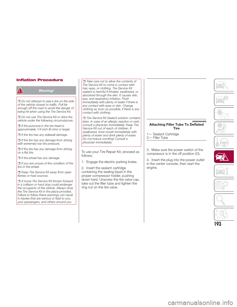
08066S0004EMAttaching Filler Tube To Deflated
Tire
1— Sealant Cartridge
2— Filler Tube
193
Page 235 of 268

Warning!
Do not use a tire, wheel size, load rating,
or speed rating other than that specified for
your vehicle. Some combinations of
unapproved tires and wheels may change
suspension dimensions and performance
characteristics, resulting in changes to
steering, handling, and braking of your
vehicle. This can cause unpredictable
handling and stress to steering and
suspension components. You could lose
control and have a collision resulting in
serious injury or death. Use only the tire
and wheel sizes with load ratings approved
for your vehicle.
Never use a tire with a smaller load
index or capacity, other than what was
originally equipped on your vehicle. Using a
tire with a smaller load index could result in
tire overloading and failure. You could lose
control and have a collision.
Failure to equip your vehicle with tires
having adequate speed capability can
result in sudden tire failure and loss of
vehicle control.
Caution!
Replacing original tires with tires of a
different size may result in false
speedometer and odometer readings.
DEPARTMENT OF
TRANSPORTATION
UNIFORM TIRE
QUALITY GRADES
The following tire grading categories
were established by the National
Highway Traffic Safety Administration.
The specific grade rating assigned by
the tire's manufacturer in each category
is shown on the sidewall of the tires on
your vehicle.
All passenger vehicle tires must
conform to Federal safety requirements
in addition to these grades.
Treadwear
The Treadwear grade is a comparative
rating, based on the wear rate of the
tire when tested under controlled
conditions on a specified government
test course. For example, a tire graded
150 would wear one and one-half times
as well on the government course as a
tire graded 100. The relative
performance of tires depends upon the
actual conditions of their use, however,
and may depart significantly from the
norm due to variations in driving habits,
service practices, and differences in
road characteristics and climate.
Traction Grades
The Traction grades, from highest to
lowest, are AA, A, B, and C. These
grades represent the tire's ability to
stop on wet pavement, as measured
under controlled conditions on specified
government test surfaces of asphalt
and concrete. A tire marked C may
have poor traction performance.
Warning!
The traction grade assigned to this tire is
based on straight-ahead braking traction
tests, and does not include acceleration,
cornering, hydroplaning, or peak traction
characteristics.
233
Page 266 of 268

Supplemental Restraint System -AirBag ................ .116
Suspension ............... .244
Symbols ....................6
Telescoping Steering Column .....31
Tie Down Hooks, Cargo .........54
Tilt Steering Column ...........31
Tire And Loading Information Placard ................ .223
Tire Markings ...............221
Tire Safety Information .........221
Tire Service Kit ..............192
Tires...............226,229,233 Aging (Life Of Tires) .........232
Air Pressure .............229
Changing ...............220
Compact Spare ...........226
Flat Changing ............192
General Information ......226,229
High Speed .............230
Inflation Pressures .........230
Jacking ............... .220
Life Of Tires .............232 Load Capacity
............223
Quality Grading ...........233
Radial ................ .231
Replacement .............232
Safety ..............221,229
Snow Tires ..............228
Spare Tire ............226,227
Spinning ...............231
Tread Wear Indicators .......231
To Open Hood ...............52
Tow Hooks, Emergency ........201
Towing Disabled Vehicle ...........200
Towing trailers ..............175
TPMS (Tire Pressure Monitoring System) ................ .106
Traction Control System (TCS) .....97
Transmission ...............242
Transporting animals .........
.176
T
ransporting passengers ........176
Transporting Pets ............133
Tread Wear Indicators ..........231
Turn Signals .................36
Uniform Tire Quality Grades .....233
Untwisting Procedure, Seat Belt . . .112
Use of the Owner’s Manual ........5
Vehicle changes/alterations.......3
Vehicle identification number .....239
Vehicle Loading ...........173,223
Vent Operation ...............42
Warning Flasher, Hazard .......180
Warranty Information ..........258
Washer fluid for windshield/headlights ........211
Washers, Windshield ...........40
Weights ................. .248
Wheel And Wheel Trim .........227
Wheel And Wheel Trim Care ......227
Wheels and tires .............221
Windows (cleaning) ...........236
Windshield wiper .............40
replacing blades ...........216
Windshield wiper/washer Smart washing function .......40
Windshield Wipers ............40
Wrecker Towing .............200
INDEX