2017 Alfa Romeo Giulia warning lights
[x] Cancel search: warning lightsPage 87 of 268

SymbolWhat It Means What To Do
ELECTRONIC THROTTLE CONTROL (ETC) WARNING
LIGHTS
This warning light, along with the related message, signals
a failure in the electronic throttle control system (ETC).Contact an authorized dealer as soon as possible.
If a failure is detected, the warning light switches on
while the engine is running.Place the ignition in the off position and the shift
selector in the park position: the warning light should
switch off. If the warning light stays on with engine
running the vehicle can still be driven.
Contact an authorized dealer as soon as possible to
have the failure eliminated.
If the warning light flashes with the engine running,
immediate intervention is required. A loss of
performance, irregular/high idling speed or engine
stopping might take place and the vehicle may need to
be towed.
Contact an authorized dealer as soon as possible to
have the failure eliminated.
LOW ENGINE OIL LEVEL
This warning light appears on the panel when the
engine oil level falls below the minimum recommended
value.
The level must also be checked using the dipstick in the
engine compartment (see chapter "Servicing and
Maintenance.")Contact an authorized dealer to have the system
checked.
ALFA STEERING TORQUE (AST) FAILURE
The switching on of the symbol signals a failure in the
automatic steering correction system.
Contact an authorized dealer to have the system
checked.
ALTERNATOR FAILURE
The switching on of the symbol with engine on
corresponds to an alternator failure.
Contact an authorized dealer as soon as possible.
85
Page 91 of 268

SymbolWhat It Means What To Do
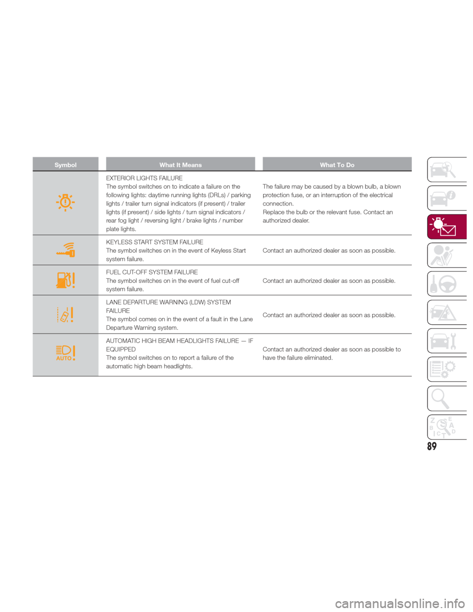
EXTERIOR LIGHTS FAILURE
The symbol switches on to indicate a failure on the
following lights: daytime running lights (DRLs) / parking
lights / trailer turn signal indicators (if present) / trailer
lights (if present) / side lights / turn signal indicators /
rear fog light / reversing light / brake lights / number
plate lights.The failure may be caused by a blown bulb, a blown
protection fuse, or an interruption of the electrical
connection.
Replace the bulb or the relevant fuse. Contact an
authorized dealer.
KEYLESS START SYSTEM FAILURE
The symbol switches on in the event of Keyless Start
system failure.
Contact an authorized dealer as soon as possible.
FUEL CUT-OFF SYSTEM FAILURE
The symbol switches on in the event of fuel cut-off
system failure.Contact an authorized dealer as soon as possible.
LANE DEPARTURE WARNING (LDW) SYSTEM
FAILURE
The symbol comes on in the event of a fault in the Lane
Departure Warning system.Contact an authorized dealer as soon as possible.
AUTOMATIC HIGH BEAM HEADLIGHTS FAILURE — IF
EQUIPPED
The symbol switches on to report a failure of the
automatic high beam headlights.Contact an authorized dealer as soon as possible to
have the failure eliminated.
89
Page 93 of 268

Warning!
If a failure is present with sharp braking, the rear wheels may lock and the vehicle may swerve.
SymbolWhat It Means What To Do
INSUFFICIENT ENGINE COOLANT LEVEL (if equipped)
If the symbol switches on, it indicates a low engine
coolant level condition.Top up, as described in the "Servicing And
Maintenance" chapter
ACTIVE CRUISE CONTROL SYSTEM FAILURE
While driving, if the warning light switches on, it signals
a failure in the Adaptive Cruise Control system.Contact an authorized dealer to have the system
checked.
WEAR ON BRAKE PADS
Lights up when the brake pads have reached their wear
limit.Contact an authorized dealer as soon as possible.Note:
Always use genuine parts or similar because the
Integrated Brake System (IBS) system could detect
anomalies.
WEAR ON CCB BRAKE DISCS if equipped)
Lights up when the carbon ceramic brake discs have
reached their wear limit.
Contact an authorized dealer as soon as possible.
Warning!
It is recommended to use only original or equivalent, bench-tested spare pads in order to ensure the original performance of the braking
system.
91
Page 95 of 268

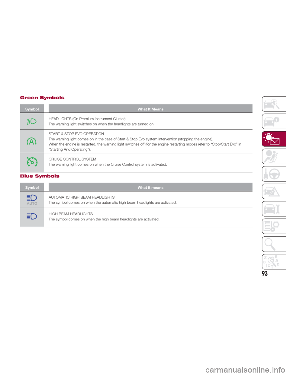
Green Symbols
SymbolWhat It Means
HEADLIGHTS (On Premium Instrument Cluster)
The warning light switches on when the headlights are turned on.
START & STOP EVO OPERATION
The warning light comes on in the case of Start & Stop Evo system intervention (stopping the engine).
When the engine is restarted, the warning light switches off (for the engine restarting modes refer to “Stop/Start Evo” in
“Starting And Operating”).
CRUISE CONTROL SYSTEM
The warning light comes on when the Cruise Control system is activated.
Blue Symbols
Symbol What it means
AUTOMATIC HIGH BEAM HEADLIGHTS
The symbol comes on when the automatic high beam headlights are activated.
HIGH BEAM HEADLIGHTS
The symbol comes on when the high beam headlights are activated.
93
Page 96 of 268

ONBOARD
DIAGNOSTIC
SYSTEM
Operation
The OBD (On Board Diagnostic system)
carries out a continuous diagnosis of
the components of the vehicle related
to emissions.
It also alerts the driver of when these
components are no longer in peak
condition by switching on the
warning light on the instrument
panel (see “Warning Lights And
Messages” paragraph in this chapter).
The aim of the OBD system (On Board
Diagnostic) is to:
Monitor the efficiency of the system
Indicate an increase in emissions
Indicate the need to replace
damaged components
The vehicle also has a connector, which
can interface with appropriate tools,
that makes it possible to read the error
codes stored in the electronic control
units together with a series of specific
parameters for engine operation and
diagnosis. This check can be carried
out by your authorized dealer.
Note: After eliminating a fault, to check
the system completely, your authorized
dealer is obliged to run tests and, if
necessary certain road tests.
Onboard Diagnostic
System (OBD II)
Cybersecurity
Your vehicle is required to have an
Onboard Diagnostic system (OBD II)
and a connection port to allow access
to information related to the
performance of your emissions
controls. Authorized service technicians
may need to access this information to
assist with the diagnosis and service of
your vehicle and emissions system.
Warning!
ONLY an authorized service technician
should connect equipment to the OBD II
connection port in order to diagnose or
service your vehicle.
If unauthorized equipment is connected
to the OBD II connection port, such as a
driver-behavior tracking device, it may:
Be possible that vehicle systems,
including safety related systems, could be
impaired or a loss of vehicle control could
occur that may result in an accident
involving serious injury or death.
Access, or allow others to access,
information stored in your vehicle systems,
including personal information.
94
GETTING TO KNOW YOUR INSTRUMENT PANEL
Page 103 of 268

Rear View
The system detects vehicles coming
from the rear part of your vehicle on
both sides and entering the rear
detection area with a difference in
speed of less than 31 mph (50 km/h)
with relation to your vehicle.
Overtaking Vehicles
If another vehicle is overtaken slowly,
with a difference in speed of less than
approximately 15 mph (25 km/h) and
the vehicle stays in the blind spot for
approximately 1.5 seconds, the
warning light on the door mirror of the
corresponding side lights up.
If the difference in speed between the
two vehicles is greater than
approximately 15 mph (25 km/h), the
warning light does not light up.
Rear Cross Path Detection (RCP)
System
This system helps the driver during
reverse maneuvers in the case of
reduced visibility.
The RCP system monitors the rear
detection areas on both sides of the
vehicle to detect objects moving
towards the sides of the vehicle, with a
minimum speed between approximately
1 mph (1 km/h) and 2 mph (3 km/h)
and objects moving at a maximum
speed of 21 mph (35 km/h), in areas
such as parking lots.
The system activation is signaled to the
driver by a visual and acoustic warning.Note:
If the sensors are covered by
objects or vehicles, the system will not
warn the driver.
Warning!
Rear Cross Path Detection (RCP) is not a
back up aid system. It is intended to be
used to help a driver detect an oncoming
vehicle in a parking lot situation. Drivers
must be careful when backing up, even
when using RCP. Always check carefully
behind your vehicle, look behind you, and
be sure to check for pedestrians, animals,
other vehicles, obstructions, and blind
spots before backing up. Failure to do so
can result in serious injury or death.
Operating Mode
The system may be activated/
deactivated via the Connect system. To
access the function, select the following
items on the main menu in sequence:
"Settings", "Safety" and "Blind Spot
Alert".
"Blind Spot Alert", "Visual" Mode
When the system is enabled, a visual
warning is sent to the door mirror on
the side of the detected object.
The visual warning on the mirror will
blink if the driver switches on the
direction indicators, thus indicating the
intention to change lane.
The warning will be fixed if the driver
stays in the same lane. "Blind Spot Alert" Function
Deactivation
When the system is deactivated ("Blind
Spot Alert" mode off), the BSM or RCP
systems will not emit either acoustic or
visual warnings.
The BSM system will store the
operating mode running when the
engine was stopped. Each time the
engine is started, the operating mode
stored previously will be recalled and
used.
General Information
This vehicle has systems that operate
on radio frequency that comply with
Part 15 of the Federal Communications
Commission (FCC) rules and with
Industry Canada Standards RSS-
GEN/210/220/310.
Operation is subject to the following
two conditions:
1. The device may not cause harmful
interference.
2. The device must accept any
interference received, including
interference that may cause undesired
operation of the device.
Changes or modifications to any of
these systems by other than an
authorized service facility could void
authorization to use this equipment.
101
Page 108 of 268

The system may activate, assessing the
trajectory of the vehicle, for the presence of
reflecting metal objects different from other
vehicles, such as safety barriers, road
signs, barriers before parking lots, tollgates,
level crossings, gates, railways, objects
near road constructions sites or higher than
the vehicle (e.g. a fly-over). In the same
way, the system may intervene inside
multi-story parking lots or tunnels, or due
to a glare on the road surface. These
possible activations are a consequence of
the real driving scenario coverage by the
system and must not be regarded as
faults.
The system has been designed for road
use only. If the vehicle is driven on a track,
the system must be deactivated to avoid
unnecessary warnings. Automatic
deactivation is signaled by the dedicated
warning light/symbol switching on in the
instrument panel (refer to the instructions in
the "Warning Lights And Messages On The
Instrument Panel" in "Getting To Know Your
Instrument Panel" for further information).
Tire Pressure
Monitoring System
(TPMS)
The vehicle is equipped with a Tire
Pressure Monitoring System (TPMS)
that sends the inflation pressure
information of each tire to the control
unit, and will signal the driver in the
event of insufficient tire pressure.
Tire pressure will vary with temperature
by approximately 1 psi (7 kPa) for every
12°F (6.5°C). This means that when the outside temperature decreases, the tire
pressure will also decrease. Tire
pressure should always be set based
on cold inflation tire pressure. This is
defined as the tire pressure after the
vehicle has not been driven for at least
three hours, or driven less than 1 mile
(1.6 km) after a three hour period. The
cold tire inflation pressure must not
exceed the maximum inflation pressure
molded into the tire sidewall. Refer to
“Tires” in “Servicing And Maintenance”
for information on how to properly
inflate the vehicle’s tires. The tire
pressure will also increase as the
vehicle is driven. This is normal, and
there should be no adjustment for this
increased pressure.
The TPMS will signal the driver if
pressure falls below the warning limit for
any reason, including the effects of low
temperature and normal loss of
pressure from the tire.
The TPMS will stop indicating
insufficient tire pressure when pressure
is equal to or greater than the
prescribed cold inflation level.
Therefore, if insufficient tire pressure is
indicated by the () warning light
displaying in the instrument cluster,
increase the inflation pressure up to the
prescribed cold inflation value.
The system will automatically update,
and the “Tire Pressure Monitoring
Telltale Light” will turn off once the
system receives the updated tire
pressures. The vehicle may need to be driven for up to 20 minutes above
15 mph (24 km/h) in order for the TPMS
to receive this information.
Operating Example
For example, your vehicle may have a
recommended cold (parked for more
than three hours) placard pressure of
33 psi (227 kPa). If the ambient
temperature is 68°F (20°C), and the
measuredtirepressureis28psi
(193 kPa), a temperature drop to 20°F
(-7°C) will decrease the tire pressure to
approximately 24 psi (165 kPa). This tire
pressure is low enough to turn ON the
“Tire Pressure Monitoring Telltale Light.”
Driving the vehicle may cause the tire
pressure to rise to approximately 28 psi
(193 kPa), but the “Tire Pressure
Monitoring Telltale Light” will still be on.
In this situation, the “Tire Pressure
Monitoring Telltale Light” will turn off
only after the tires are inflated to the
vehicle’s recommended cold placard
pressure value.
106
SAFETY
Page 118 of 268

Redundant Air Bag Warning
Light
If a fault with the Air Bag Warning
Light is detected, which could affect the
Supplemental Restraint System (SRS),
the Redundant Air Bag Warning Light
will illuminate on the instrument panel.
The Redundant Air Bag Warning Light
will stay on until the fault is cleared. In
addition, a single chime will sound to
alert you that the Redundant Air Bag
Warning Light has come on and a fault
has been detected. If the Redundant Air
Bag Warning Light comes on
intermittently or remains on while driving
have an authorized dealer service the
vehicle immediately. For additional
information regarding the Redundant Air
Bag Warning Light, refer to “Warning
Lights And Messages” in the “Getting to
Know Your Instrument Panel” section of
this manual.
Front Air Bags
This vehicle has front air bags and
lap/shoulder belts for both the driver
and front passenger. The front air bags
are a supplement to the seat belt
restraint systems. The driver front air
bag is mounted in the center of the
steering wheel. The passenger front air
bag is mounted in the instrument panel,
above the glove compartment. The
words “SRS AIRBAG” or “AIRBAG” are
embossed on the air bag covers.
Warning!
Being too close to the steering wheel or
instrument panel during front air bag
deployment could cause serious injury,
including death. Air bags need room to
inflate. Sit back, comfortably extending
your arms to reach the steering wheel or
instrument panel.
Never place a rear-facing child restraint
in front of an air bag. A deploying
passenger front air bag can cause death or
serious injury to a child 12 years or
younger, including a child in a rear-facing
child restraint.
Only use a rear-facing child restraint in a
vehicle with a rear seat.
Driver And Passenger Front Air
Bag Features
The Advanced Front Air Bag system
has multistage driver and front
passenger air bags. This system
provides output appropriate to the
severity and type of collision as
determined by the Occupant Restraint
Controller (ORC), which may receive
information from the front impact
sensors (if equipped) or other system
components.
The first stage inflator is triggered
immediately during an impact that
requires air bag deployment. A low
energy output is used in less severe
06106S0001EMDriver Air Bag
06106S0002EMPassenger Air Bag
116
SAFETY