Page 57 of 90
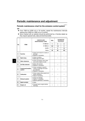
Periodic maintenance an d a djustment
7-14
7
TIP
If the specified idling speed cannot be
obtained as described above, have a
Yamaha dealer make the adjustment.
EAU21385
Checkin g the throttle grip free
play
The throttle grip free play should mea-
sure 4.0–6.0 mm (0.16–0.24 in) at the
inner edge of the throttle grip. Periodi-
cally check the throttle grip free play
and, if necessary, have a Yamaha deal-
er adjust it.
En gine i dlin g spee d:
1600–1800 r/min
1. Throttle grip free play
1
UB5181E0.book Page 14 Monday, April 6, 2015 9:22 AM
Page 58 of 90

Periodic maintenance an d a djustment
7-15
7
EAU21402
Valve clearance
The valve clearance changes with use,
resulting in improper air-fuel mixture
and/or engine noise. To prevent this
from occurring, the valve clearance
must be adjusted by a Yamaha dealer
at the intervals specified in the periodic
maintenance and lubrication chart.
EAU40916
Tires
Tires are the only contact between the
vehicle and the road. Safety in all con-
ditions of riding depends on a relatively
small area of road contact. Therefore, it
is essential to maintain the tires in good
condition at all times and replace them
at the appropriate time with the speci-
fied tires.
Tire air pressure
The tire air pressure should be
checked and, if necessary, adjusted
before each ride.
WARNING
EWA15371
Operation of this vehicle with im-
proper tire pressure may cause se-
vere injury or d eath from loss of
control.
The tire air pressure must be
checked and a djuste d on col d tires
(i.e., when the temperature of the
tires equals the am bient tempera-
ture).
Stan dar d tire air pressure:
Front: 100 kPa (1.00 kgf/cm², 15 psi)
Rear:
100 kPa (1.00 kgf/cm², 15 psi)
UB5181E0.book Page 15 Monday, April 6, 2015 9:22 AM
Page 59 of 90

Periodic maintenance an d a djustment
7-16
7
Tire inspection
The tires must be checked before each
ride. If the center tread depth reaches
the specified limit, if the tire has a nail
or glass fragments in it, or if the side-
wall is cracked, have a Yamaha dealer
replace the tire immediately.
Tire information
This model is equipped with tube tires.
Tires age, even if they have not been
used or have only been used occasion-
ally. Cracking of the tread and sidewall
rubber, sometimes accompanied by
carcass deformation, is an evidence of
ageing. Old and aged tires shall be
checked by tire specialists to ascertain
their suitability for further use.
WARNING
EWA10462
The front an
d rear tires shoul d b e of
the same make an d d esi gn, other-
wise the han dlin g characteristics of
the vehicle may be different, which
coul d lea d to an acci dent.
After extensive tests, only the tires list-
ed below have been approved for this
model by Yamaha.
WARNING
EWA15542
Have a Yamaha dealer replace
excessively worn tires. Operat-
in g the motorcycle with exces-
sively worn tires decreases
ri din g sta bility an d can lead to
loss of control.
The replacement of all wheel-
and b rake-relate d parts, inclu d-
in g the tires, shoul d b e left to a
Yamaha dealer, who has the
necessary professional knowl-
e dg e an d experience.
It is not recommen ded to patch
a puncture d tu be. If unavoi d-
a b le, however, patch the tu be
very carefully an d replace it as
soon as possi ble with a hi gh-
quality pro duct.
Ride conservatively after
chan gin g a tire since the tire
must seat itself on the rim prop-
erly. Failure to allow proper
seatin g may cause tire failure,
which may result in damag e to
the motorcycle an d injury to the
ri der.
1. Tire sidewall
2. Tire tread depth
Minimum tire trea d d epth (front an d
rear): 4.0 mm (0.16 in)
1
2
Front tire:
Size: 2.50-14 4PR
Manufacturer/model:
CHEN SHIN/C-803-2
Rear tire: Size:
3.00-12 4PR
Manufacturer/model: CHEN SHIN/C-803-2
UB5181E0.book Page 16 Monday, April 6, 2015 9:22 AM
Page 60 of 90

Periodic maintenance an d a djustment
7-17
7
EAU21944
Spoke wheels
WARNING
EWA10611
The wheels on this mo del are not
d esi gne d for use with tu beless tires.
Do not attempt to use tu beless tires
on this mo del.
To maximize the performance, durabil-
ity, and safe operation of your motor-
cycle, note the following points
regarding the specified wheels.
The wheel rims should be
checked for cracks, bends, warp-
age or other damage, and the
spokes for looseness or damage
before each ride. If any damage is
found, have a Yamaha dealer re-
place the wheel. Do not attempt
even the smallest repair to the
wheel. A deformed or cracked
wheel must be replaced.
The wheel should be balanced
whenever either the tire or wheel
has been changed or replaced. An
unbalanced wheel can result in
poor performance, adverse han-
dling characteristics, and a short-
ened tire life.
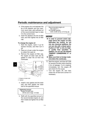
EAU44664
Adjustin g the clutch free play
The clutch free play must be checked
and, if necessary, adjusted as follows
at the intervals specified in the periodic
maintenance and lubrication chart.
1. Loosen the locknut.
2. Slowly turn the clutch adjusting screw in direction (a) until resis-
tance is felt, and then turn it 1/8
turn in direction (b).
3. Tighten the locknut to the speci- fied torque.
TIP
When tightening the locknut, hold the
clutch adjusting screw with a screw-
driver so that it does not turn together
with the locknut.
1. Locknut
2. Clutch adjusting screw
Tightening torque:
Locknut:
8 Nm (0.8 m·kgf, 5.8 ft·lbf)
1 2
(a)(b)
UB5181E0.book Page 17 Monday, April 6, 2015 9:22 AM
Page 61 of 90

Periodic maintenance an d a djustment
7-18
7
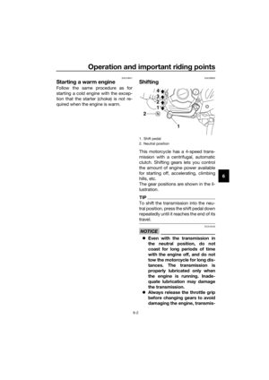
EAU44886
A djustin g the brake lever free
play
Measure the brake lever free play as
shown.
Periodically check the brake lever free
play and, if necessary, adjust it as fol-
lows.
1. Slide the rubber cover back.
2. Loosen the locknut at the brake le- ver.
3. To increase the brake lever free play, turn the brake lever free play
adjusting bolt in direction (a). To
decrease the brake lever free play,
turn the adjusting bolt in direction
(b).
TIP
Skip steps 4–7 if the specified brake le-
ver free play could be obtained as de-
scribed above.
4. Fully turn the adjusting bolt at thebrake lever in direction (a) to loos-
en the brake cable. 5. Loosen the locknut at the brake
shoe plate.
6. To increase the brake lever free play, turn the adjusting bolt at the
brake shoe plate in direction (a).
To decrease the brake lever free
play, turn the adjusting bolt in di-
rection (b).
7. Tighten the locknut at the brake shoe plate.
8. Tighten the locknut at the brake lever, and then slide the rubber
cover to its original position.
1. Rubber cover
2. Brake lever free play adjusting bolt
3. Locknut
4. Brake lever free play
Brake lever free play:10.0–20.0 mm (0.39–0.79 in)
3
21
(b)
(a) 4
1. Locknut
2. Brake lever free play adjusting bolt
2
1
(b)
(a)
UB5181E0.book Page 18 Monday, April 6, 2015 9:22 AM
Page 62 of 90

Periodic maintenance an d a djustment
7-19
7
EAU44673
A djustin g the brake pe dal free
play
Measure the brake pedal free play at
the brake pedal end as shown.
Periodically check the brake pedal free
play and, if necessary, adjust it as fol-
lows.
To increase the brake pedal free play,
turn the brake pedal free play adjusting
nut at the brake rod in direction (a). To
decrease the brake pedal free play,
turn the adjusting nut in direction (b).
WARNING
EWA14821
After a djustin g the drive chain
slack or removin g an d installin g
the rear wheel, always check
the brake pe dal free play.
If proper a djustment cannot b e
o btaine d as descri bed , have a
Yamaha dealer make this a d-
justment.
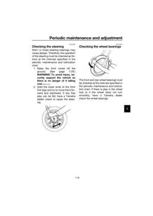
EAU44821
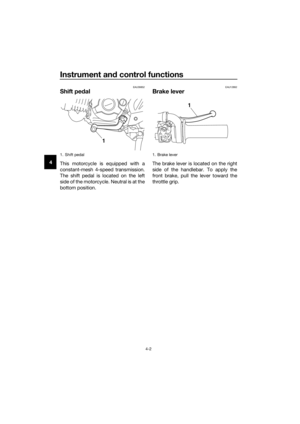
Checkin g the shift pe dal
The operation of the shift pedal should
be checked before each ride. If opera-
tion is not smooth, have a Yamaha
dealer check the vehicle.
1. Brake pedal free play adjusting nut
2. Brake pedal free play
Brake ped al free play:
10.0–20.0 mm (0.39–0.79 in)
UB5181E0.book Page 19 Monday, April 6, 2015 9:22 AM
Page 63 of 90

Periodic maintenance an d a djustment
7-20
7
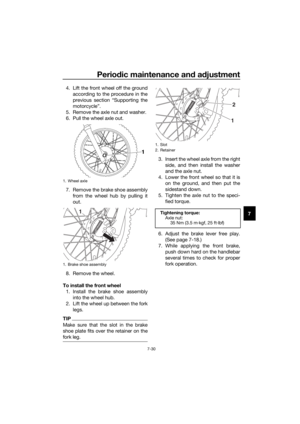
EAU22363
Checkin g the front an d rear
b rake shoes
Front
Rear
The front and rear brake shoes must be
checked for wear at the intervals spec-
ified in the periodic maintenance and
lubrication chart. Each brake is provid-
ed with a wear indicator, which allows
you to check the brake shoe wear with-
out having to disassemble the brake.
To check the brake shoe wear, check
the position of the wear indicator while
applying the brake. If a brake shoe has
worn to the point that the wear indica-
tor reaches the wear limit line, have a
Yamaha dealer replace the brake shoes as a set.
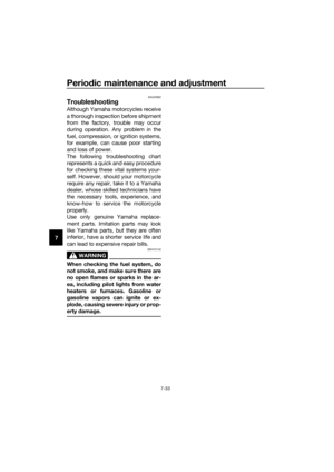
EAU22762
Drive chain slack
The drive chain slack should be
checked before each ride and adjusted
if necessary.
EAU22776To check the d rive chain slack
1. Place the motorcycle on the side- stand.
TIP
When checking and adjusting the drive
chain slack, there should be no weight
on the motorcycle.
2. Shift the transmission into the neutral position.
3. Measure the drive chain slack as shown.
4. If the drive chain slack is incorrect, adjust it as follows.
EAU40115To a djust the drive chain slack
Consult a Yamaha dealer before ad-
justing the drive chain slack. 1. Loosen the brake pedal free play adjusting nut, axle nut, and lock-
nut at each end of the swingarm.
1. Brake shoe wear indicator
2. Brake shoe wear limit line
1. Brake shoe wear indicator
2. Brake shoe wear limit line
2
1
12
Drive chain slack:
40.0–56.0 mm (1.57–2.20 in)
1. Drive chain slack
1
UB5181E0.book Page 20 Monday, April 6, 2015 9:22 AM
Page 64 of 90
. To loosen the drive chain,
turn the")
Periodic maintenance an d a djustment
7-21
7
2. To tighten the drive chain, turn thedrive chain slack adjusting nut at
each end of the swingarm in direc-
tion (a). To loosen the drive chain,
turn the adjusting nut at each end
of the swingarm in direction (b),
and then push the rear wheel for-
ward. NOTICE: Improper drive
chain slack will overload the en-
g ine as well as other vital parts
of the motorcycle an d can lead
to chain slippa ge or breakag e.
To prevent this from occurrin g,
keep the d rive chain slack with-
in the specifie d limits.
[ECA10572]
TIP
Using the alignment marks on each
side of the swingarm, make sure that
both drive chain pullers are in the same
position for proper wheel alignment.
3. Tighten the axle nut and both
locknuts to the specified torques.
4. Adjust the brake pedal free play. (See page 7-19.)
5. Make sure that the drive chain pullers are in the same position,
the drive chain slack is correct,
and the drive chain moves
smoothly.
1. Brake pedal free play adjusting nut
2. Locknut
3. Drive chain slack adjusting nut
1. Axle nut
2. Locknut
3. Drive chain slack adjusting nut
32
1
1. Alignment marks
2. Locknut
3. Drive chain slack adjusting nut
4. Drive chain puller
Ti
ghtening torques:
Axle nut:
60 Nm (6.0 m·kgf, 43 ft·lbf)
Locknut: 7 Nm (0.7 m·kgf, 5.1 ft·lbf)
(a)
(b)
432 1
UB5181E0.book Page 21 Monday, April 6, 2015 9:22 AM