Page 89 of 114
Periodic maintenance and adjustment6-34
1
2
3
4
567
8
9
10
11
12
check the electrical system.
EAU58001
Replacing the headlight bulbThis model is equipped with a halogen
bulb headlight. If the headlight bulb
burns out, replace it as follows.NOTICE
ECA10651
Take care not to damage the follow-
ing parts:
Headlight bulb
Do not touch the glass part of
the headlight bulb to keep it free
from oil, otherwise the transpar-
ency of the glass, the luminosity
of the bulb, and the bulb life will
be adversely affected. Thor-
oughly clean off any dirt and fin-
gerprints on the headlight bulb
using a cloth moistened with al-
cohol or thinner.
Headlight lens
Do not affix any type of tinted
film or stickers to the headlight
lens.
Do not use a headlight bulb of awattage higher than specified.
1. Remove the headlight unit side
covers by removing the bolts on
each side.
1. Do not touch the glass part of the bulb.
1. Bolt
1
1
B87-9-E0_1.book 34 ページ 2015年12月16日 水曜日 午前10時21分
Page 90 of 114
Periodic maintenance and adjustment
6-35
1
2
3
4
56
7
8
9
10
11
12 2. Pull up the headlight unit cover to
separate it from the headlight unit.
3. Remove the grommets. 4. Disconnect the auxiliary light cou-
pler.
5. Disconnect the headlight coupler, and then remove the headlight unit
from the vehicle. 6. Remove the headlight bulb cover.
7. Unhook the headlight bulb holder,
then remove the burnt-out bulb.
1. Bolt
2. Headlight unit side cover
1. Headlight unit cover1
1
2
21
1. Grommet
1. Auxiliary light coupler1
1
1. Headlight coupler
1. Headlight bulb cover
1
1
B87-9-E0_1.book 35 ページ 2015年12月16日 水曜日 午前10時21分
Page 91 of 114
Periodic maintenance and adjustment6-36
1
2
3
4
567
8
9
10
11
12
8. Place a new headlight bulb into po-
sition, then secure it with the bulb
holder.
9. Install the headlight bulb cover.
10. Install the headlight unit as shown, and then connect the headlight
coupler. 11. Connect the auxiliary light coupler.
12. Align the holes in the headlight unit
with the holes in the headlight unit
cover.
13. Install the grommets.
14. Place the headlight unit side cov- ers in their original position, and
then install the bolts.
15. Have a Yamaha dealer adjust the headlight beam if necessary.
EAU58021
Replacing an aux iliary light
bulbThis model is equipped with two auxil-
iary lights. If an auxiliary light bulb burns
out, replace it as follows.
1. Remove the headlight unit side covers by removing the bolts on
each side.
1. Headlight bulb holder
2. Headlight bulb
12
1. Headlight unit
2. Headlight coupler1
2
1. Bolt
1
1
B87-9-E0_1.book 36 ページ 2015年12月16日 水曜日 午前10時21分
Page 92 of 114
Periodic maintenance and adjustment
6-37
1
2
3
4
56
7
8
9
10
11
12 2. Remove the auxiliary light bulb
socket (together with the bulb) by
turning it counterclockwise.
3. Remove the burnt-out bulb by pull- ing it out. 4. Insert a new bulb into the socket.
5. Install the socket (together with the
bulb) by turning it clockwise.
6. Place the headlight unit side cov- ers in their original position, and
then install the bolts.
EAU70540
Brake/tail lightThis model is equipped with an
LED-type brake/tail light.
If the brake/tail light does not come on,
have a Yamaha dealer check it.
1. Bolt
2. Headlight unit side cover
1. Auxiliary light bulb socket1
1
2
2
1
1. Auxiliary light bulb1
B87-9-E0_1.book 37 ページ 2015年12月16日 水曜日 午前10時21分
Page 93 of 114
Periodic maintenance and adjustment6-38
1
2
3
4
567
8
9
10
11
12
EAU24205
Replacing a turn signal light
bulb1. Remove the turn signal light lens by removing the screw.
2. Remove the burnt-out bulb by pushing it in and turning it counter-
clockwise. 3. Insert a new bulb into the socket,
push it in, and then turn it clock-
wise until it stops.
4. Install the lens by installing the screw. NOTICE: Do not over-
tighten the screw, otherwise the
lens may break.
[ECA11192] EAU58010
Replacing the license plate
light bulb1. Remove the license plate light unit
by removing the nuts and collars,
and then remove the license plate
light bulb socket (together with the
bulb) by pulling it out.
2. Remove the burnt-out bulb by pull- ing it out.
1. Turn signal light lens
2. Screw
1
2
1. Turn signal light bulb
1
1. License plate light unit
2. Collar
3. Nut
4. License plate light bulb socket
1
22
4
3
3
B87-9-E0_1.book 38 ページ 2015年12月16日 水曜日 午前10時21分
Page 94 of 114
 by pushing it in, and then in-
stall the license")
Periodic maintenance and adjustment
6-39
1
2
3
4
56
7
8
9
10
11
12 3. Insert a new bulb into the socket.
4. Install the socket (together with the
bulb) by pushing it in, and then in-
stall the license plate light unit by
installing the collars and nuts.
EAU67131
Supporting the motorcycleSince this model is not equipped with a
centerstand, use maintenance stands
when removing the front or rear wheel
or when performing other maintenance
that requires the motorcycle to stand up
right.
Check that the motorcycle is in a stable
and level position before starting any
maintenance.
EAU44792
Front wheel (for non-ABS
models)
WARNING
EWA14841
For the ABS model, have a Yamahadealer remove and install the wheel.
EAU56270
To remove the front wheel
WARNING
EWA10822
To avoid injury, securely support the
vehicle so there is no danger of itfalling over.
1. Loosen the front wheel axle pinch bolt, then the wheel axle and the
brake caliper bolts.
1. License plate light bulb
1
1. Maintenance stand (example)
1
B87-9-E0_1.book 39 ページ 2015年12月16日 水曜日 午前10時21分
Page 95 of 114

Periodic maintenance and adjustment6-40
1
2
3
4
567
8
9
10
11
12
2. Lift the front wheel off the ground
according to the procedure in the
previous section “Supporting the
motorcycle”.
3. Remove the brake caliper on each side by removing the bolts.
NOTICE: Do not apply the brake
after the brake calipers have
been removed, otherwise the
brake pads will be forced
shut.
[ECA11052]
4. Pull the wheel axle out, and then remove the wheel.
To install the front wheel 1. Lift the wheel up between the fork legs.
2. Insert the wheel axle.
3. Install the brake calipers by install- ing the bolts.TIPMake sure that there is enough space
between the brake pads before install-
ing the brake calipers onto the brakediscs.
4. Lower the front wheel so that it is on the ground, and then put the
sidestand down.
5. Tighten the wheel axle, the front wheel axle pinch bolt and the
brake caliper bolts to the specified
torques.
6. Push down hard on the handlebar several times to check for proper
fork operation.
1. Front wheel axle pinch bolt
2. Wheel axle
3. Brake caliper bolt
3
2
1
1. Brake caliper bolt
2. Brake caliper12
Tightening torques:Wheel axle:65 Nm (6.5 m·kgf, 47 ft·lbf)
Front wheel axle pinch bolt: 23 Nm (2.3 m·kgf, 17 ft·lbf)
Brake caliper bolt:
35 Nm (3.5 m·kgf, 25 ft·lbf)
B87-9-E0_1.book 40 ページ 2015年12月16日 水曜日 午前10時21分
Page 96 of 114

WARNING
EWA14841
For the ABS model, have a Yamahadealer remove and install the wheel.
EAU56")
Periodic maintenance and adjustment
6-41
1
2
3
4
56
7
8
9
10
11
12
EAU44802
Rear wheel (for non-ABS
models)
WARNING
EWA14841
For the ABS model, have a Yamahadealer remove and install the wheel.
EAU56701
To remove the rear wheel
WARNING
EWA10822
To avoid injury, securely support the
vehicle so there is no danger of itfalling over. 1. Loosen the axle nut. 2. Lift the rear wheel off the ground
according to the procedure on
page 6-39.
3. Remove the axle nut.
4. Fully loosen the locknut on each side of the swingarm.
5. Turn the drive chain slack adjust- ing bolts fully in direction (a) and
push the wheel forward. 6. Remove the drive chain from the
rear sprocket.
TIP
If the drive chain is difficult to re-
move, remove the wheel axle first,
and then lift the wheel upward
enough to remove the drive chain
from the rear sprocket.
The drive chain cannot be disas-sembled.
7. While supporting the brake caliper bracket, pull the wheel axle out,
and then remove the wheel.
NOTICE: Do not apply the brake
after the wheel and brake disc
1. Axle nut
1
1. Drive chain slack adjusting bolt
2. Locknut
(a)1
2
B87-9-E0_1.book 41 ページ 2015年12月16日 水曜日 午前10時21分
 1
1 2
2 3
3 4
4 5
5 6
6 7
7 8
8 9
9 10
10 11
11 12
12 13
13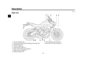 14
14 15
15 16
16 17
17 18
18 19
19 20
20 21
21 22
22 23
23 24
24 25
25 26
26 27
27 28
28 29
29 30
30 31
31 32
32 33
33 34
34 35
35 36
36 37
37 38
38 39
39 40
40 41
41 42
42 43
43 44
44 45
45 46
46 47
47 48
48 49
49 50
50 51
51 52
52 53
53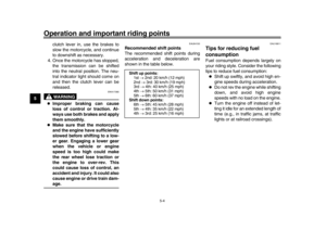 54
54 55
55 56
56 57
57 58
58 59
59 60
60 61
61 62
62 63
63 64
64 65
65 66
66 67
67 68
68 69
69 70
70 71
71 72
72 73
73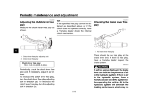 74
74 75
75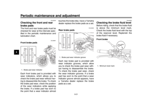 76
76 77
77 78
78 79
79 80
80 81
81 82
82 83
83 84
84 85
85 86
86 87
87 88
88 89
89 90
90 91
91 92
92 93
93 94
94 95
95 96
96 97
97 98
98 99
99 100
100 101
101 102
102 103
103 104
104 105
105 106
106 107
107 108
108 109
109 110
110 111
111 112
112 113
113


 by
turning it counterclockwise.
3. Remove the burnt-out bulb by pu")
