Page 25 of 114

Instrument and control functions
3-10
1
234
5
6
7
8
9
10
11
12
indicator goes off when the vehicle is
stopped.
TIPConsider the following tips to reduce
fuel consumption:
Avoid high engine speeds during
acceleration.
Travel at a constant speed.
Select the transmission gear that
is appropriate for the vehiclespeed.
Transmission gear display
This display shows the selected gear.
The neutral position is indicated by “ ” and by the neutral indicator light.
Drive mode display
MT09
MT09A
This display indicates which drivemode has been selected: “STD”, “A” or
“B”. For more details on the modes and
on how to select them, see pages 3-15
and 3-17.
TCS display (for equipped models)
MT09A
This display indicates which traction
control system setting has been select-
ed: “1”, “2” or “OFF”. For more details
on the TCS settings and on how to se-
lect them, see page 3-21.
1. Transmission gear display
2. Neutral indicator light “ ”1
2
1. Drive mode display
1. Drive mode display
11
1. TCS display
1
B87-9-E0_1.book 10 ページ 2015年12月16日 水曜日 午前10時21分
Page 26 of 114

Instrument and control functions
3-11
1
23
4
5
6
7
8
9
10
11
12 Multi-function display
The multi-function display is equipped
with the following:
an odometer
two tripmeters (which show the
distance traveled since they were
last reset)
a fuel reserve tripmeter (which
shows the distance traveled since
the last segment of the fuel meter
started flashing)
an instantaneous fuel consump-
tion display
an average fuel consumption dis-
play
a coolant temperature display
an air intake temperature display
self-diagnosis mode (MT09)
a brightness control display
TIP
The odometer will lock at 999999
and cannot be reset.
The tripmeters will lock at 9999.9but can be manually reset.
Push the “SELECT” button to switch
the display between the instantaneous
fuel consumption mode “km/L” or “L/
100 km”, average fuel consumption
mode “AVE_ _._ km/L” or “AVE_ _._ L/
100 km”, coolant temperature mode
“ C”, air intake temperature mode “Air_
_ C”, odometer mode “ODO”, and trip-
meter modes “TRIP 1” and “TRIP 2” in
the following order:
km/L or L/100 km AVE_ _._ km/L or
AVE_ _._ L/100 km C Air_ _ C
ODO TRIP 1 TRIP 2
For the UK:
Push the “SELECT” button to switch
the display between the instantaneous
fuel consumption mode “km/L”, “L/100
km” or “MPG”, average fuel consump-
tion mode “AVE_ _._ km/L”, “AVE_ _._ L/100 km” or “AVE_ _._ MPG”, coolant
temperature mode “
C”, air intake tem-
perature mode “Air_ _ C”, odometer
mode “ODO”, and tripmeter modes
“TRIP 1” and “TRIP 2” in the following
order:
km/L, L/100 km or MPG AVE_ _._
km/L, AVE_ _._ L/100 km or AVE_ _._
MPG C Air_ _ C ODO
TRIP 1 TRIP 2
TIP
Push the “RESET” button to switch
the display in the reverse order.
The fuel reserve tripmeter and
self-diagnosis modes come on au-tomatically.
If the last segment of the fuel meter
starts flashing (“ ” wi ll also flash for
MT09), the display automatically
changes to the fuel reserve tripmeter
mode “F-TRIP” and starts counting the
distance traveled from that point. In this
case, push the “SELECT” button to
switch the display in the following order:
F-TRIP km/L or L/100 km AVE_
_._ km/L or AVE_ _._ L/100 km C
1. Multi-function display
1
B87-9-E0_1.book 11 ページ 2015年12月16日 水曜日 午前10時21分
Page 27 of 114

Instrument and control functions
3-12
1
234
5
6
7
8
9
10
11
12
Air_ _ C ODO TRIP 1 TRIP
2 F-TRIP
For the UK:
F-TRIP km/L, L/100 km or MPG
AVE_ _._ km/L, AVE_ _._ L/100 km or
AVE_ _._ MPG C Air_ _ C
ODO TRIP 1 TRIP 2 F-TRIP
TIP
To reset a tripmeter, select it by
pushing the “SELECT” button, and
then push the “RESET” button for
one second.
If you do not reset the fuel reserve
tripmeter manually, it resets auto-
matically and disappears after re-fueling and traveling 5 km (3 mi). Instantaneous fuel consumption
mode
The instantaneous fuel consumption
display can be set to either “km/L”, “L/
100 km” or “MPG” (for the UK).
“km/L”: The distance that can be
traveled on 1.0 L of fuel under the
current riding conditions is shown.
“L/100 km”: The amount of fuel
necessary to travel 100 km under
the current riding conditions is
shown.
“MPG” (for the UK): The distance
that can be traveled on 1.0 Imp.gal
of fuel under the current riding con-
ditions is shown.
To switch between the instantaneous fuel consumption display settings, push
the “SELECT” button for one second.
TIPIf traveling at speeds under 20 km/h (12mi/h), “_ _._” is displayed.
Average fuel consumption mode
This display shows the average fuel
consumption since it was last reset.
The average fuel consumption display
can be set to either “AVE_ _._ km/L”,
“AVE_ _._ L/100 km” or “AVE_ _._
MPG” (for the UK).
“AVE_ _._ km/L”: The average dis-
tance that can be traveled on 1.0 L
of fuel is shown.
1. Instantaneous fuel consumption display
1
1. Average fuel consumption display
1
B87-9-E0_1.book 12 ページ 2015年12月16日 水曜日 午前10時21分
Page 28 of 114
: The
av")
Instrument and control functions
3-13
1
23
4
5
6
7
8
9
10
11
12
“AVE_ _._ L/100 km”: The average
amount of fuel necessary to travel
100 km is shown.
“AVE_ _._ MPG” (for the UK): The
average distance that can be trav-
eled on 1.0 Imp.gal of fuel is
shown.
To switch between the average fuel
consumption display settings, push the
“SELECT” button for one second.
To reset the average fuel consumption,
push the “RESET” button for one sec-
ond.
TIPAfter resetting the average fuel con-
sumption, “_ _._” will be shown until thevehicle has traveled 1 km (0.6 mi). Coolant temperature mode
This display shows the coolant temper-
ature from 40
C to 116 C in 1 C incre-
ments.
If the message “HI” flashes, stop the
vehicle, then stop the engine, and let
the engine cool. (See page 6-45.)
TIP
When the coolant temperature is
below 40 C, “LO” will be dis-
played.
The coolant temperature varies
with changes in the weather andengine load. Air intake temperature mode
The air intake temperature display indi-
cates the temperature of the air drawn
into the air filter case.
This display shows the air intake tem-
perature from –9
C to 99 C in 1 C in-
crements.
TIP
–9 C will be displayed even if the
air intake temperature falls below
–9 C.
The air intake temperature may
vary from the ambient tempera-ture.
1. Coolant temperature display
1
1. Air intake temperature display
1
B87-9-E0_1.book 13 ページ 2015年12月16日 水曜日 午前10時21分
Page 29 of 114

This model is equipped with a self-diag-
nosis device for vari
ous electrical cir-
cuits.
If a problem is dete")
Instrument and control functions
3-14
1
234
5
6
7
8
9
10
11
12
Self-diagnosis mode (MT09)
This model is equipped with a self-diag-
nosis device for vari
ous electrical cir-
cuits.
If a problem is detected in any of those
circuits, the engine trouble warning light
will come on and the display will indi-
cate an error code.
If the display indicates any error codes,
note the code number, and then have a
Yamaha dealer check the vehicle.
The self-diagnosis device also detects
problems in the immobilizer system cir-
cuits.
If a problem is detected in the immobi- lizer system circuits, the immobilizer
system indicator light will flash and the
display will indicate an error code.
TIPIf the display indicates error code 52,
this could be caused by transponder in-
terference. If this error code appears,try the following.
1. Use the code re-registering key to start the engine.TIPMake sure there are no other immobi-
lizer keys close to the main switch, and
do not keep more than one immobilizer
key on the same key ring! Immobilizer
system keys may cause signal interfer-
ence, which may prevent the enginefrom starting.
2. If the engine starts, turn it off and try starting the engine with the
standard keys.
3. If one or both of the standard keys do not start the engine, take the
vehicle, the code re-registering
key and both standard keys to a
Yamaha dealer and have the stan-
dard keys re-registered.
NOTICE
ECA11591
If the display indicates an error
code, the vehicle should be checked
as soon as possible in order to avoidengine damage.
Brightness control mode
The brightness of the multi-function
meter unit panel can be adjusted.
To adjust the brightness1. Turn the key to “OFF”.
2. While pushing the “SELECT” but-ton, turn the key to “ON” and con-
tinue pushing the button until the
display switches to the brightness
1. Error code display
2. Engine trouble warning light “ ”
3. Immobilizer system indicator light “ ”
1
2
3
1. Brightness level display
1
B87-9-E0_1.book 14 ページ 2015年12月16日 水曜日 午前10時21分
Page 30 of 114

Instrument and control functions
3-15
1
23
4
5
6
7
8
9
10
11
12 control mode.
3. Push the “RESET” button to set the brightness level.
4. Push the “SELECT” button to con- firm the selected brightness level
and exit the brightness control
mode.
EAU47634
D-mode (drive mode)D-mode is an electronically controlled
engine performance system with three
mode selections (“STD”, “A”, and “B”).
Push the drive mode switch “MODE” to
switch between modes. (See page
3-17 for an explanation of the drive
mode switch.)TIPBefore using D-mode, make sure you
understand its operation along with theoperation of the drive mode switch.
Mode “STD”
Mode “STD” is suitable for various rid-
ing conditions. This mode allows the rider to enjoy
smooth and sporty drivability from the
low-speed range to the high-speed
range.
Mode “A”
Mode “A” offers a sportier engine re-
sponse in the low- to mid-speed range
compared to mode “STD”.
Mode “B”
Mode “B” offers response that is some-
what less sharp compared to mode
“STD” for riding situations that require
especially sensitive throttle operation.1. Drive mode switch “MODE”
1
B87-9-E0_1.book 15 ページ 2015年12月16日 水曜日 午前10時21分
Page 31 of 114
Instrument and control functions
3-16
1
234
5
6
7
8
9
10
11
12
EAU1234K
Handlebar switchesLeft (MT09) Left (MT09A) Right
EAU12352
Pass switch “ ”
Press this switch to flash the headlight.TIPWhen the dimmer switch is set to “ ”,the passing switch has no effect.
EAU12401
Dimmer switch “ / ”
Set this switch to “ ” for the high
beam and to “ ” for the low beam.
1. Pass switch “ ”
2. Dimmer switch “ / ”
3. Turn signal switch “ / ”
4. Horn switch “ ”
2341
1. Pass switch “ ”
2. Dimmer switch “ / ”
3. Turn signal switch “ / ”
4. Horn switch “ ”
5. Traction control system switch “TCS”
2341
5
1. Start/Engine stop switch “ / / ”
2. Drive mode switch “MODE”
3. Hazard switch “ ”
123
B87-9-E0_1.book 16 ページ 2015年12月16日 水曜日 午前10時21分
Page 32 of 114

Instrument and control functions
3-17
1
23
4
5
6
7
8
9
10
11
12
EAU12461
Turn signal switch “ / ”
To signal a right-hand turn, push this
switch to “ ”. To signal a left-hand
turn, push this switch to “ ”. When re-
leased, the switch returns to the center
position. To cancel the turn signal
lights, push the switch in after it has re-
turned to the center position.
EAU12501
Horn switch “ ”
Press this switch to sound the horn.
EAU73441
Traction control system switch
“TCS” (for equipped models)
With the throttle closed, push this
switch down to change from TCS “1” to
“2”. Push up to change from TCS “2” to
“1”.
With the vehicle stopped, push this
switch up for two seconds to turn the
system off. Push down to turn the sys-
tem on.TIP
The current TCS setting is shown
in the TCS display (page 3-10).
See page 3-21 for an explanation of the traction control system and
the TCS settings.
EAU54212
Stop/Run/Start switch “ / / ”
To crank the engine with the starter, set
this switch to “ ”, and then push the
switch down towards “ ”. See page
5-2 for starting instructions prior to
starting the engine.
Set this switch to “ ” to stop the engine
in case of an emergency, such as when
the vehicle overturns or when the throt-
tle cable is stuck.
EAU41701
The engine trouble warning light will
come on when the key is turned to “ON”
and the start switch is pushed, but this
does not indicate a malfunction.
EAU12735
Hazard switch “ ”
With the key in the “ON” or “ ” posi-
tion, use this switch to turn on the haz-
ard lights (simultaneous flashing of all
turn signal lights).
The hazard lights are used in case of
an emergency or to warn other drivers
when your vehicle is stopped where it
might be a traffic hazard.
NOTICE
ECA10062
Do not use the hazard lights for an
extended length of time with the en-
gine not running, otherwise the bat-tery may discharge.
EAU47496
Drive mode switch “MODE”
WARNING
EWA15341
Do not change the D-mode while thevehicle is moving.
Using this switch changes the drive
mode to “STD”, “A”, or “B” in the follow-
ing order:
STD
A B STD
The throttle grip must be completely
closed in order to change the drive
mode. (See page 3-15 for an explana-
tion of each drive mode.)TIP
The mode is set to “STD” by de-
fault. The mode resets to “STD”
when the key is turned to “OFF”.
B87-9-E0_1.book 17 ページ 2015年12月16日 水曜日 午前10時21分
 1
1 2
2 3
3 4
4 5
5 6
6 7
7 8
8 9
9 10
10 11
11 12
12 13
13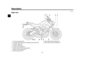 14
14 15
15 16
16 17
17 18
18 19
19 20
20 21
21 22
22 23
23 24
24 25
25 26
26 27
27 28
28 29
29 30
30 31
31 32
32 33
33 34
34 35
35 36
36 37
37 38
38 39
39 40
40 41
41 42
42 43
43 44
44 45
45 46
46 47
47 48
48 49
49 50
50 51
51 52
52 53
53 54
54 55
55 56
56 57
57 58
58 59
59 60
60 61
61 62
62 63
63 64
64 65
65 66
66 67
67 68
68 69
69 70
70 71
71 72
72 73
73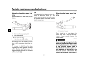 74
74 75
75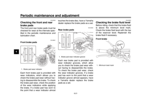 76
76 77
77 78
78 79
79 80
80 81
81 82
82 83
83 84
84 85
85 86
86 87
87 88
88 89
89 90
90 91
91 92
92 93
93 94
94 95
95 96
96 97
97 98
98 99
99 100
100 101
101 102
102 103
103 104
104 105
105 106
106 107
107 108
108 109
109 110
110 111
111 112
112 113
113 Left (MT09A) Right
EAU12352
Pass switch “ ”
Press this switch to flash the headlight.TIPWhen")