2016 VOLVO XC90 T8 light
[x] Cancel search: lightPage 213 of 546

LOADING AND STORAGE
211
Related information
•Passenger compartment storage spaces (p. 208)
• Electrical sockets (p. 212)
• Alarm (p. 226)
• Rear climate system controls on the tunnelconsole (p. 190)
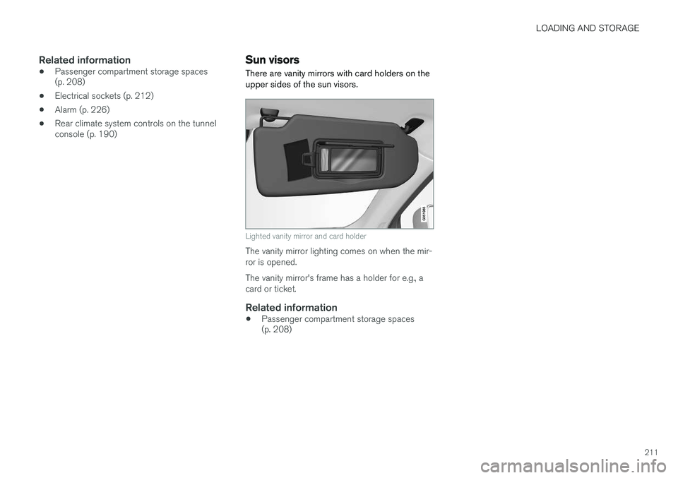
Sun visors There are vanity mirrors with card holders on the upper sides of the sun visors.
Lighted vanity mirror and card holder
The vanity mirror lighting comes on when the mir- ror is opened. The vanity mirror's frame has a holder for e.g., a card or ticket.
Related information
• Passenger compartment storage spaces (p. 208)
Page 214 of 546

LOADING AND STORAGE
* Option/accessory, for more information, see Introduction.
212
Electrical sockets There are two 12-volt sockets in the tunnel con- sole, a 120-volt socket on the rear side of thetunnel console, and one 12-volt socket in the cargo area *.
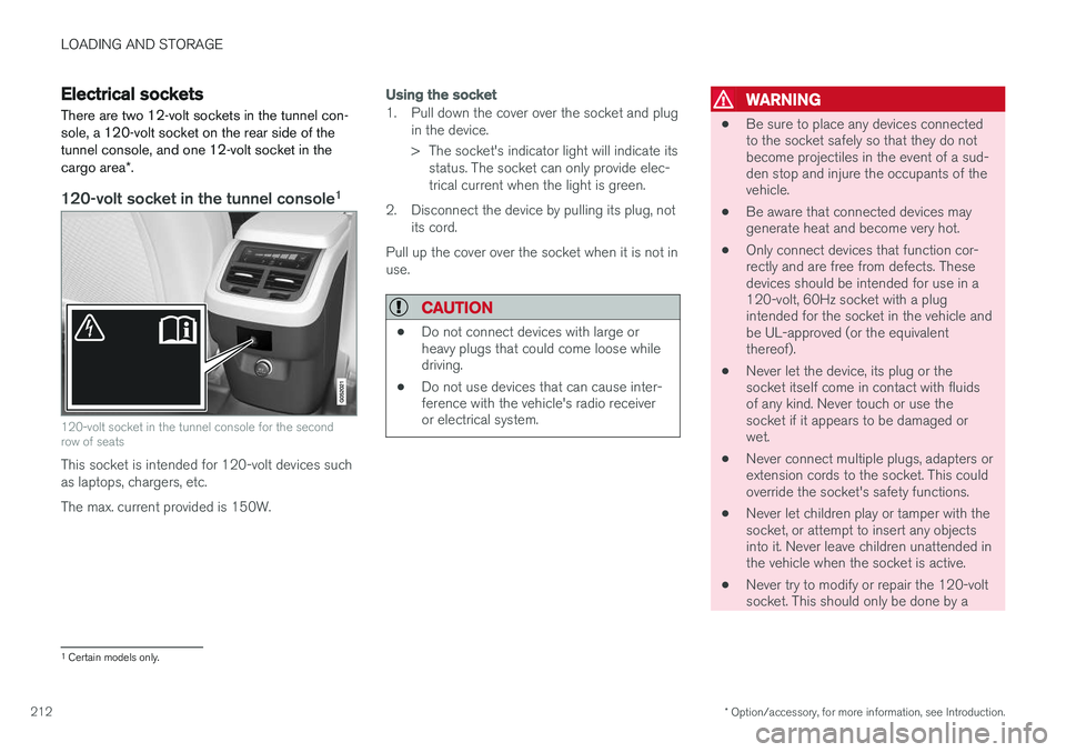
120-volt socket in the tunnel console 1
120-volt socket in the tunnel console for the second row of seats
This socket is intended for 120-volt devices such as laptops, chargers, etc. The max. current provided is 150W.
Using the socket
1. Pull down the cover over the socket and plug
in the device.
> The socket's indicator light will indicate itsstatus. The socket can only provide elec- trical current when the light is green.
2. Disconnect the device by pulling its plug, not its cord.
Pull up the cover over the socket when it is not inuse.
CAUTION
• Do not connect devices with large or heavy plugs that could come loose whiledriving.
• Do not use devices that can cause inter-ference with the vehicle's radio receiveror electrical system.
WARNING
• Be sure to place any devices connected to the socket safely so that they do notbecome projectiles in the event of a sud-den stop and injure the occupants of thevehicle.
• Be aware that connected devices maygenerate heat and become very hot.
• Only connect devices that function cor-rectly and are free from defects. Thesedevices should be intended for use in a120-volt, 60Hz socket with a plugintended for the socket in the vehicle andbe UL-approved (or the equivalentthereof).
• Never let the device, its plug or thesocket itself come in contact with fluidsof any kind. Never touch or use thesocket if it appears to be damaged orwet.
• Never connect multiple plugs, adapters orextension cords to the socket. This couldoverride the socket's safety functions.
• Never let children play or tamper with thesocket, or attempt to insert any objectsinto it. Never leave children unattended inthe vehicle when the socket is active.
• Never try to modify or repair the 120-voltsocket. This should only be done by a
1
Certain models only.
Page 215 of 546

LOADING AND STORAGE
}}
213
trained and qualified Volvo service techni- cian.
Failure to follow the points above could result in electrical shock and/or serious injury.Status indication
An LED (Light Emitting Diode) on the socket indicates its status:
Status indicator lightSocket statusAction
Steady green lightThe socket is providing current to a connected device.None.
Flashing orange lightThe socket's voltage converter is too hot (the connected device draws too much current, etc. or the temperature in the passenger compartment is very high).Unplug the device, let the converter cool down and plug in the device again.
The connected device draws too much current (constantly or currently) or is not functioning properly.None. The device should not be plugged into the socket.
Indicator light offThe socket has not detected a plugged in device.Be sure the device is correctly plugged into the socket.
The socket is not active.Put the vehicle's ignition in at least mode I.
The socket has been active but has been deactivated.Start the engine and/or charge the start battery.
If a problem persists, have the socket checked by a trained and qualified Volvo service technician.
Page 217 of 546

LOADING AND STORAGE
}}
* Option/accessory, for more information, see Introduction.215
Loading
The load carrying capacity of your vehicle is determined by factors such as the number ofpassengers, the amount of cargo, the weight ofany accessories that may be installed, etc.
Tailgate opening button on the lighting panel
Open the tailgate by pressing the button on the lighting panel, pressing the
button on the
remote key or by using the optional foot move- ment sensor under the rear bumper.
Loading recommendations
• Load objects in the cargo compartment against the backrest whenever possible.
• If the backrests of the second row seats arefolded down, they should not be in contactwith the front seat backrests. This could impede the function of the WhiplashProtection System (WHIPS).
• Unstable loads can be secured to the loadanchoring eyelets with straps or web lash-ings to help keep them from shifting.
• Stop the engine and apply the parking brakewhen loading or unloading long objects. Thegear selector can be knocked out of positionby long loads, which could set the vehicle inmotion.
WARNING
•
Stop the engine, put the gear selector in P
, and apply the parking brake when
loading or unloading long objects.
• The vehicle's driving characteristics may change depending on the weight and dis-tribution of the load.
• A 44-pound (20 kg) object produces aforce of 2,200 pounds (1,000 kg) in ahead-on collision at 30 mph (50 km/h).
• The cargo area and rear seat should notbe loaded to a level higher than 2 in.(5 cm) below the upper edge of the rearside windows. Objects placed higher thanthis level could impede the function ofthe Inflatable Curtain.
WARNING
•
Cover sharp edges on long loads to help prevent injury to occupants. Secure theload to help prevent shifting during sud-den stops.
• Always secure large and heavy objectswith a seat belt or cargo retaining straps.
• Always secure the load to help prevent itfrom moving in the event of sudden stops.
• Switch off the engine, apply the parking brake and put the gear selector in
P
when loading and unloading the vehicle.
Raising/lowering the rear-end of the vehicle *
Using the buttons on the read edge of the cargo compartment, the rear-end of the vehicle (thelevel of the cargo compartment floor) can beraised or lowered for easier loading or to make attaching a trailer 2
simpler.
2 An accessory trailer hitch can be purchased from a Volvo retailer.
Page 220 of 546

||
LOADING AND STORAGE
218
WARNING
•Objects in the cargo compartment should always be securely anchored.
• The nets upper hooks must be securelyinserted into the ceiling mounting pointsand the lower spring hooks must besecurely hooked onto the cargo anchor-ing eyelets.
• A damaged net must never be used.
Attaching1. Fold out the cargo net and fold out the upper
rod. Be sure it locks in position.
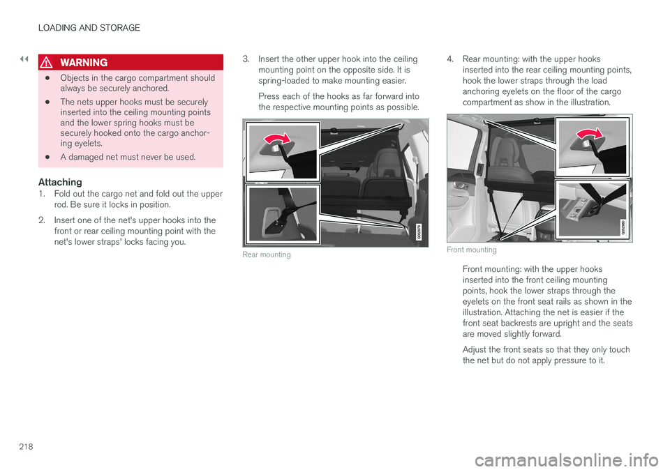
2. Insert one of the net's upper hooks into the front or rear ceiling mounting point with the net's lower straps' locks facing you. 3. Insert the other upper hook into the ceiling
mounting point on the opposite side. It isspring-loaded to make mounting easier. Press each of the hooks as far forward into the respective mounting points as possible.
Rear mounting
4. Rear mounting: with the upper hooks inserted into the rear ceiling mounting points, hook the lower straps through the loadanchoring eyelets on the floor of the cargocompartment as show in the illustration.
Front mounting
Front mounting: with the upper hooks inserted into the front ceiling mountingpoints, hook the lower straps through theeyelets on the front seat rails as shown in theillustration. Attaching the net is easier if thefront seat backrests are upright and the seatsare moved slightly forward. Adjust the front seats so that they only touch the net but do not apply pressure to it.
Page 224 of 546

||
LOADING AND STORAGE
222
Partially retracted
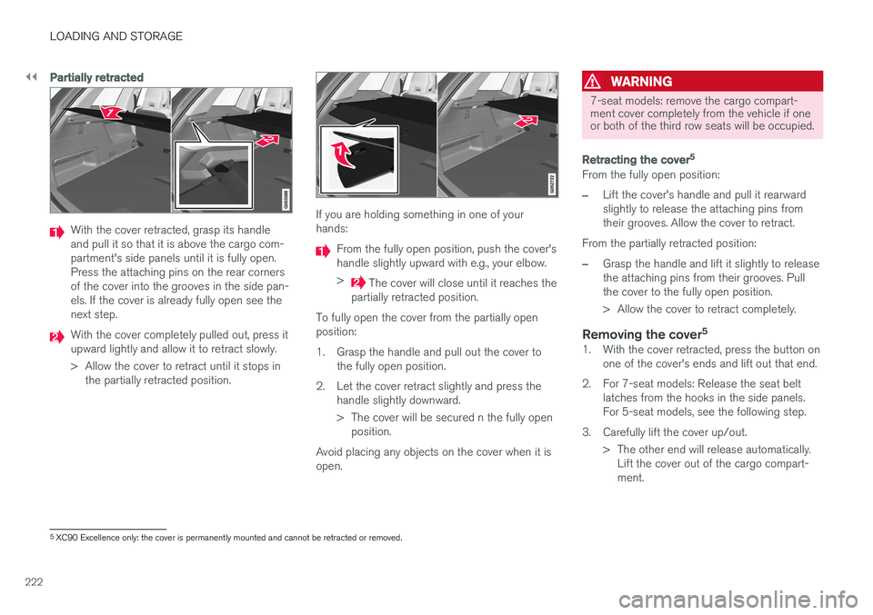
With the cover retracted, grasp its handle and pull it so that it is above the cargo com-partment's side panels until it is fully open.Press the attaching pins on the rear cornersof the cover into the grooves in the side pan-els. If the cover is already fully open see thenext step.
With the cover completely pulled out, press it upward lightly and allow it to retract slowly.
> Allow the cover to retract until it stops inthe partially retracted position.
If you are holding something in one of your hands:
From the fully open position, push the cover's handle slightly upward with e.g., your elbow. >
The cover will close until it reaches the
partially retracted position.
To fully open the cover from the partially open position:
1. Grasp the handle and pull out the cover to the fully open position.
2. Let the cover retract slightly and press the handle slightly downward.
> The cover will be secured n the fully openposition.
Avoid placing any objects on the cover when it is open.
WARNING
7-seat models: remove the cargo compart- ment cover completely from the vehicle if oneor both of the third row seats will be occupied.
Retracting the cover 5
From the fully open position:
–Lift the cover's handle and pull it rearward slightly to release the attaching pins fromtheir grooves. Allow the cover to retract.
From the partially retracted position:
–Grasp the handle and lift it slightly to release the attaching pins from their grooves. Pullthe cover to the fully open position.
> Allow the cover to retract completely.
Removing the cover 51. With the cover retracted, press the button on
one of the cover's ends and lift out that end.
2. For 7-seat models: Release the seat belt latches from the hooks in the side panels. For 5-seat models, see the following step.
3. Carefully lift the cover up/out. > The other end will release automatically.Lift the cover out of the cargo compart-ment.
5XC90 Excellence only: the cover is permanently mounted and cannot be retracted or removed.
Page 229 of 546

LOCKS AND ALARM
* Option/accessory, for more information, see Introduction.227
Arming the alarm
–Lock the vehicle by pressing the remote key's lock button, pressing the outer indenta- tion for locking on one of the door handles1
or by pressing the tailgate's rubberized pres-sure plate 1
.
If the vehicle is equipped with a power tail- gate *, the button on the lower edge of the
tailgate can also be used to lock the vehicle and arm the alarm.
Disarming the alarm
–Unlock the vehicle by pressing the remote key's unlock button, pressing the pressure-sensitive area on the inside of one of the door handles 1
or by pressing the tailgate's
rubberized pressure plate 1
.
Turning off a triggered (sounding) alarm
–Press the remote key's unlock button or put the ignition in mode I by turning the start
knob to START and releasing it.
Alarm signalsThe following occurs if the alarm has been trig- gered:
• A siren will sound for 30 seconds or until the alarm is turned off
• All turn signals flash for 5 minutes or untilthe alarm is turned off If the door that triggered the alarm is left open,
the alarm cycle will be repeated 10 times.
Alarm indicatorA red indicator light on the upper side of the dashboard shows the alarm's status:
• Indicator off: the alarm is disarmed
• Indicator flashes once every two seconds: the alarm is armed
• Indicator flashes quickly after the alarm hasbeen disarmed until the ignition has been put in mode
I (turn the start knob to START and
release it): the alarm has been triggered
Related information
• Automatically arming/disarming the alarm (p. 228)
• Deactivating the alarm without a functioningremote key (p. 228)
1
Models withe the optional Passive Entry only.
Page 230 of 546

LOCKS AND ALARM
* Option/accessory, for more information, see Introduction.
228
Automatically arming/disarming the alarm
Automatically arming the alarm helps prevent inadvertently leaving the vehicle without alarmprotection.
If the vehicle has been unlocked with the remote key (and the alarm has been disarmed) but nodoor or the tailgate has been opened within2 minutes, the vehicle will automatically relockand the alarm will re-arm. In certain markets, the alarm will be re-armed automatically after a slight delay after the driver'sdoor has been opened and closed without beinglocked.
Related information
• Alarm (p. 226)
• Deactivating the alarm without a functioning remote key (p. 228)
Deactivating the alarm without a functioning remote key
If the remote key is not functioning properly, the alarm can be turned off and the vehicle can bestarted as follows:
1. Unlock and open the driver's door with the detachable key blade.
> This will trigger the alarm.
Location of the back-up key reader in the cup holder
2. Place the remote key on the back-up keyreader in the tunnel console's cup holder.
3. Turn the start knob to START and release it.
> The alarm will turn off.
Related information
• Alarm (p. 226)
• Detachable key blade (p. 237)
• Starting the engine (p. 372)
• Automatically arming/disarming the alarm (p. 228)
Child safety locks
Child safety locks help prevent children from inadvertently opening one of the rear doors frominside the vehicle.
Electronic * activation/deactivationThe electronic child safety locks can be acti- vated/deactivated as long as the ignition is notcompletely switched off and this can be done forup to two minutes after the engine has beenswitched off if no door has been opened. To activate:
Child safety lock button on the driver door control panel
1. Switch on the ignition or start the engine.