2016 SUBARU WRX low beam
[x] Cancel search: low beamPage 228 of 594

Headlight beam leveler (if
equipped) & Automatic headlight beam
leveler (models with LED
headlights) The LED headlights generate more light
than conventional halogen headlights.
Therefore a driver of an oncoming vehicle
may experience too much glare if your
headlight beam height adjustment is high
when the vehicle is carrying a heavy load.
The automatic headlight beam leveler
adjusts the headlight beam height auto-
matically and optimally according to the
load being carried by the vehicle. Fog light switch (if equipped)
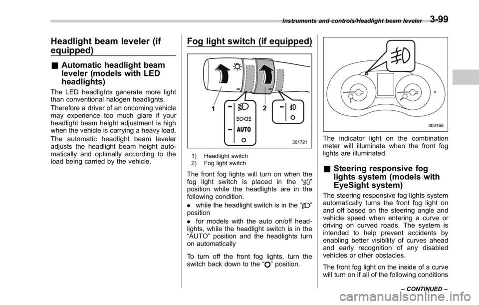
1) Headlight switch
2) Fog light switch
The front fog lights will turn on when the
fog light switch is placed in the “
”
position while the headlights are in the
following condition.
. while the headlight switch is in the “
”
position
. for models with the auto on/off head-
lights, while the headlight switch is in the
“ AUTO ” position and the headlights turn
on automatically
To turn off the front fog lights, turn the
switch back down to the “
” position. The indicator light on the combination
meter will illuminate when the front fog
lights are illuminated.
& Steering responsive fog
lights system (models with
EyeSight system) The steering responsive fog lights system
automatically turns the front fog light on
and off based on the steering angle and
vehicle speed when entering a curve or
driving on curved roads. The system is
intended to help prevent accidents by
enabling better visibility of curves ahead
and early recognition of any disabled
vehicles or other obstacles.
The front fog light on the inside of a curve
will turn on if all of the following conditionsInstruments and controls/Headlight beam leveler
– CONTINUED –3-99
Page 229 of 594

Instruments and controls/Fog light switch
are met.
. The light control switch is in the “
”
position
. The light control switch is in the
“ AUTO ” position and the low beam head-
lights turn on automatically
. The fog light switch is in the “
”
position
. The low beam mode is selected (the
turn signal lever is in the center position)
. The select lever is in a position other
than the “ R ” position
. The steering responsive fog lights
system has not been deactivated
. The operating conditions such as the
steering angle and vehicle speed are met
The front fog lights on both sides will turn
on as usual if all of the following conditions
are met.
. The light control switch is in the “
”
position
. The light control switch is in the
“ AUTO ” position and the low beam head-
lights turn on automatically
. The fog light switch is in the “
”
position
. The low beam mode is selected (the
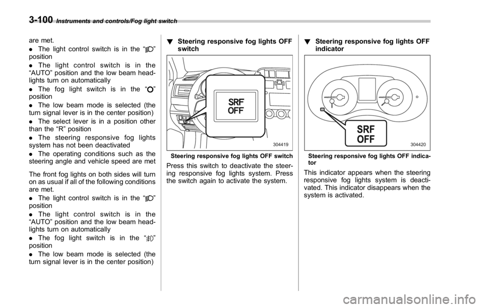
turn signal lever is in the center position) ! Steering responsive fog lights OFF
switch
Steering responsive fog lights OFF switch
Press this switch to deactivate the steer-
ing responsive fog lights system. Press
the switch again to activate the system. ! Steering responsive fog lights OFF
indicator
Steering responsive fog lights OFF indica-
tor
This indicator appears when the steering
responsive fog lights system is deacti-
vated. This indicator disappears when the
system is activated.3-100
Page 277 of 594

Audio/Tips for operating the audio/visual system
! CD player and disc
. This CD player is intended for use with
4.7 in. (12 cm) discs only.
. Extremely high temperatures can keep
the CD player from working. On hot days,
use the air conditioning system to cool the
inside of the vehicle before using the
player.
. Bumpy roads or other vibrations may
make the CD player skip.
. If moisture gets into the CD player, the
discs may not be able to be played.
Remove the discs from the player and
wait until it dries.
WARNINGCD players use an invisible laser
beam which could cause hazardous
radiation exposure if directed out-
side the unit. Be sure to operate the
player correctly.
Audio CDs
. Use only discs marked as shown
above. The following products may not be playable on your player:
– SACD
– dts CD
– Copy-protected CD
– Video CD
Special shaped discs Transparent/translucent discs
Low quality discs5-22
Page 448 of 594

& BSD/RCTA approach indica-
tor light/warning buzzer When the BSD/RCTA is active, the BSD/
RCTA approach indicator light and warn-
ing buzzer will operate to alert the driver to
the presence of the following vehicles.
. Vehicles in the neighboring lanes
. Vehicles approaching from the left or
right rear side when reversing
! BSD/RCTA approach indicator light
BSD/RCTA approach indicator light
It is mounted in each side of the outside
mirrors and will illuminate when a vehicle
approaching from behind is detected. If a
light illuminates and the turn signal lever is
operated toward the side in which this light
turned on, the indicator light flashes to warn the driver of dangers. When rever-
sing the vehicle, the indicator light flashes
when the system detects a vehicle ap-
proaching from either side.
! BSD/RCTA approach indicator
light dimming function
When the headlights are turned on, the
brightness of the BSD/RCTA approach
indicator light will be reduced.
NOTE . When affected by direct sunlight,
you may have difficulty recognizing
the BSD/RCTA approach indicator light.
. When affected by the headlight
beams from the vehicles behind, you
may have difficulty recognizing the
BSD/RCTA approach indicator light.
. While the illumination brightness
control dial is in the fully upward
position, even if the headlights are
turned on, the brightness of the BSD/
RCTA approach indicator light will not
be reduced. For details about the
illumination brightness control dial,
refer to “ Illumination brightness con-
trol ” F 3-98.
! BSD/RCTA approach warning buz-
zer (only when reversing)
A warning buzzer sounds along with
flashing of the BSD/RCTA approach in- dicator light to warn the driver of dangers.
The setting of the warning buzzer volume
can be changed by operating the multi
information display of the combination
meter. For details, refer to “ BSD/RCTA ”
F 3-48.
! Safety tips regarding the BSD/RCTA
approach indicator light/warning
buzzer
. In the following cases, operation of the
BSD/RCTA approach indicator light and
the warning buzzer may be delayed or the
system may fail to issue these warnings.
– When a vehicle moves to the
neighboring lane from a lane next to
the neighboring lane
– When driving on a steep incline or
on repeated sharp uphill and downhill
grades
– When going beyond a pass
– When both your vehicle and a
vehicle driving on a neighboring lane
are driving on the far side of each lane.
– When several narrowly-spaced ve-
hicles are approaching in a row
– In low radius bends (tight bends or
when making turns at an intersection)
– When there is a difference in height
between your lane and the neighbor-
ing lane
– Immediately after the BSD/RCTA is Starting and operating/BSD/RCTA
– CONTINUED –7-59
Page 491 of 594

Maintenance and service
Tires and wheels .............................................. 11-31Types of tires ................................................... 11-31
Tire pressure monitoring system (TPMS) (if
equipped) ....................................................... 11-31
Tire inspection ................................................. 11-32
Tire pressures and wear ................................... 11-33
Wheel balance .................................................. 11-35
Wear indicators ................................................ 11-35
Tire rotation direction mark .............................. 11-36
Tire rotation ..................................................... 11-36
Tire replacement .............................................. 11-36
Wheel replacement ........................................... 11-37
Aluminum wheels ............................................. 11-38
Windshield washer fluid .................................. 11-38
Replacement of wiper blades .......................... 11-39Windshield wiper blade assembly ..................... 11-40
Windshield wiper blade rubber ......................... 11-40 Battery .............................................................. 11-41
Fuses ................................................................ 11-42
Installation of accessories .............................. 11-44
Replacing bulbs ............................................... 11-44Headlights (models with LED headlights) .......... 11-44
High beam headlight ........................................ 11-44
Low beam headlight (models without LED
headlights), front side marker light (if
equipped), parking light (models without LED
headlights) and front turn signal light ............. 11-46
Front fog light (if equipped) .............................. 11-47
Rear combination lights ................................... 11-48
License plate light ........................................... 11-49
Other bulbs ..................................................... 11-49
Replacing battery ............................................. 11-50Replacing battery of access key ....................... 11-50
Replacing transmitter battery ........................... 11-51
Page 533 of 594

Maintenance and service/Installation of accessories
Installation of accessories Always consult your SUBARU dealer
before installing fog lights or any other
electrical equipment in your vehicle. Such
accessories may cause the electronic
system to malfunction if they are incor-
rectly installed or if they are not suited for
the vehicle.
Replacing bulbs WARNINGBulbs may become very hot while
illuminated. Before replacing bulbs,
turn off the lights and wait until the
bulbs cool down. Otherwise, there is
a risk of sustaining a burn injury.
CAUTION. Replace any bulb only with a new
bulb of the specified wattage.
Using a bulb of different wattage
could result in a fire. For the
specified wattage of each bulb,
refer to “ Bulb chart ” F 12-16.
. Do not touch the glass portion of
the light bulb with bare hands.
When holding the glass portion
is unavoidable, hold it using with
a clean dry cloth to avoid getting
moisture and grease on the bulb.
If there is any fingerprints or
grease on the bulb surface, wipe
them away with a soft cloth
moistened with alcohol. Also, if
the bulb is scratched or dropped,
it may blow out or crack. & Headlights (models with LED
headlights)
The LED headlight warning light illumi-
nates if the LED headlights malfunction.
Have your vehicle inspected at a
SUBARU dealer as soon as possible.
& High beam headlight
NOTE . If headlight aiming is required, con-
sult your SUBARU dealer for proper
adjustment of the headlight aim.
. It may be difficult to replace the
bulbs. Have the bulbs replaced by your
SUBARU dealer if necessary.
Perform the following steps to replace the
bulbs.11-44
Page 535 of 594

Maintenance and service/Replacing bulbs
the headlight assembly by turning it clock-
wise.
4. Replace the bulb with new one. At this
time, use care not to touch the bulb
surface.
5. To install the bulb to the headlight
assembly, turn it to the reverse direction
until it clicks.
6. Reconnect the electrical connector.
7. Left-hand side: Set the washer fluid
filler pipe to the original place and secure it
by clip.
Right-hand side: Install the air intake
duct with clips.
& Low beam headlight (models
without LED headlights),
front side marker light (if
equipped), parking light
(models without LED head-
lights) and front turn signal
light
NOTE . If headlight aiming is required, con-
sult your SUBARU dealer for proper
adjustment of the headlight aim.
. It may be difficult to replace the
bulbs. Have the bulbs replaced by your
SUBARU dealer if necessary.
1. Start the engine and turn the steering wheel fully in the opposite direction of the
bulb to be replaced.
2. Stop the engine.
3. Remove the clips from the mud guard.
4. Pull off the mud guard. ! Low beam headlight
1. Disconnect the electrical connector
from the bulb as pushing the tab.11-46
Page 553 of 594

Specifications/Fuses and circuits
& Fuse panel located in the engine compartment! STI
A) Main fuse Fuse
panel Fuse
rating Circuit
1 30A
. ABS unit
. Vehicle Dynamics Con-
trol unit
2 25A
. Main fan (cooling fan)
3 25A
. Sub fan (cooling fan)
4
Empty
5
25A
. Audio
6
30A
. Headlight (low beam)
7
15A
. Headlight (high beam)
8 20A
. Back-up
9 15A
. Horn
10 25A
. Rear window defogger
. Mirror heater
11 15A
. Fuel pump
12 10A
. Transmission control
unit
13 7.5A
. Engine control unit
14 15A
. Turn and hazard warn-
ing flasher
15 15A
. Tail and illumination re-
lay
16 7.5A
. Alternator12-12