2016 SUBARU IMPREZA glove box
[x] Cancel search: glove boxPage 18 of 594
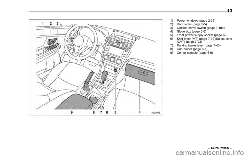
1) Power windows (page 2-35)
2) Door locks (page 2-5)
3) Outside mirror switch (page 3-108)
4) Glove box (page 6-6)
5) Front power supply socket (page 6-8)
6) Shift lever (MT) (page 7-22)/Select lever(CVT) (page 7-23)
7) Parking brake lever (page 7-40)
8) Cup holder (page 6-7)
9) Center console (page 6-6)
–CONTINUED –
13
Page 79 of 594

Seat, seatbelt and SRS airbags/*SRS airbag (Supplemental Restraint System airbag)
&SUBARU advanced frontal
airbag system
Your vehicle is equipped with a SUBARU
advanced frontal airbag system that com-
plies with the new advanced frontal airbag
requirements in the amended Federal
Motor Vehicle Safety Standard (FMVSS)
No. 208.
The SUBARU advanced frontal airbag
system automatically determines the de-
ployment force of the driver ’s SRS frontal
airbag at the time of deployment as well as
whether or not to activate the front
passenger ’s SRS frontal airbag and, if
activated, the deployment force of the
SRS frontal airbag at the time of deploy-
ment.
Your vehicle has warning labels on the
driver ’s and front passenger ’s sun visors
beginning with the phrase “EVEN WITH
ADVANCED AIR BAGS” and a tag
attached to the glove box lid beginning
with the phrase “Even with Advanced Air
Bags”. Make sure that you carefully read
the instructions on the warning labels and
tag.
Always wear your seatbelt. The SUBARU
advanced frontal airbag system is a
supplemental restraint system and must
be used in combination with a seatbelt. All
occupants should wear a seatbelt or be
seated in an appropriate child restraint system.
For the locations of the SRS airbags, refer
to
“Components” F1-46.
In a moderate to severe frontal collision,
the following components deploy.
. SRS frontal airbag for driver
. SRS frontal airbag for front passenger
. SRS knee airbag for driver
. SRS curtain airbag*
1
*1: When an offset frontal collision that is severe
enough to deploy the front airbag occurs.
These components supplement the seat-
belts by reducing the impact to the
occupant ’s head, chest and knees.
! Driver ’s SRS frontal airbag
The driver ’s SRS frontal airbag uses a
dual stage inflator. The inflator operates in
different ways depending on the severity
of impact.
Have the system inspected by your
SUBARU dealer immediately if the SRS
airbag system warning light illuminates.
NOTE
The driver ’s SRS side airbag and SRS
curtain airbag are not controlled by the
SUBARU advanced frontal airbag sys-
tem. !
Front passenger ’s SRS frontal air-
bag
The front passenger ’s SRS frontal airbag
uses a dual stage inflator. The inflator
operates in different ways depending on
the severity of impact.
The occupant detection system sensor is
installed under the seat upholstery and
monitors the physique and posture of the
front passenger. Using this information,
the occupant detection system determines
whether the front passenger ’s SRS frontal
airbag should be deployed or not.
The occupant detection system may not
inflate the front passenger ’s SRS frontal
airbag even when the driver ’s SRS frontal
airbag deploys. This is normal. In this
case, although the front passenger ’s SRS
frontal airbag does not operate, the front
passenger ’s seatbelt pretensioner oper-
ates with the driver ’s seatbelt preten-
sioner. For details about the seatbelt
pretensioner, refer to “Front seatbelt pre-
tensioners ”F 1-20.
CAUTION
Observe the following precautions.
Failure to do so may prevent the
SUBARU advanced frontal airbag
system from functioning correctly
or cause the system to fail.
1-48
Page 104 of 594
Keys
NOTE
For models with“keyless access with
push-button start system ”, refer to
“Keyless access with push-button start
system ”F 2-9.
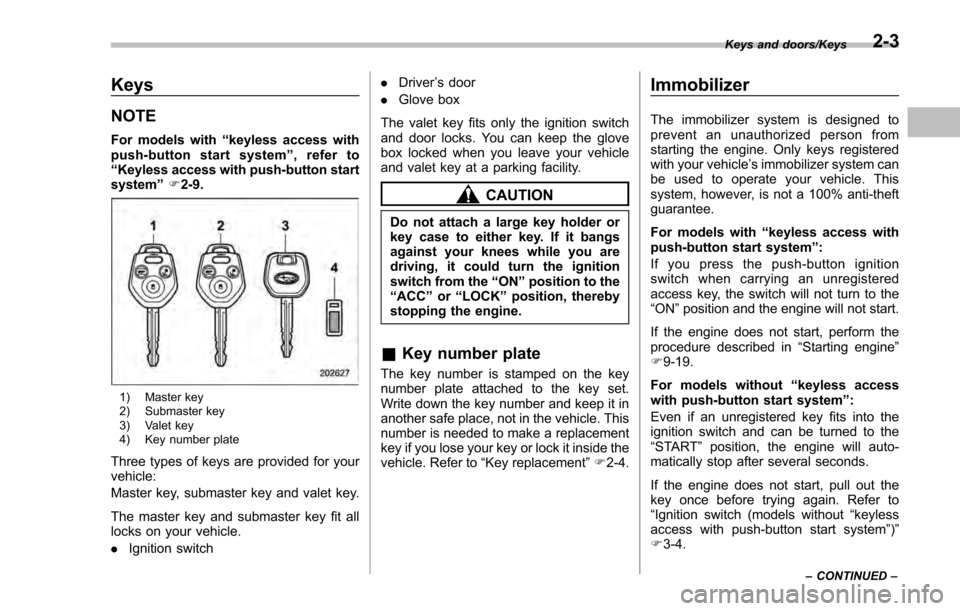
1) Master key
2) Submaster key
3) Valet key
4) Key number plate
Three types of keys are provided for your
vehicle:
Master key, submaster key and valet key.
The master key and submaster key fit all
locks on your vehicle.
. Ignition switch .
Driver ’s door
. Glove box
The valet key fits only the ignition switch
and door locks. You can keep the glove
box locked when you leave your vehicle
and valet key at a parking facility.
CAUTION
Do not attach a large key holder or
key case to either key. If it bangs
against your knees while you are
driving, it could turn the ignition
switch from the “ON”position to the
“ACC ”or “LOCK ”position, thereby
stopping the engine.
& Key number plate
The key number is stamped on the key
number plate attached to the key set.
Write down the key number and keep it in
another safe place, not in the vehicle. This
number is needed to make a replacement
key if you lose your key or lock it inside the
vehicle. Refer to “Key replacement ”F 2-4.
Immobilizer
The immobilizer system is designed to
prevent an unauthorized person from
starting the engine. Only keys registered
with your vehicle’ s immobilizer system can
be used to operate your vehicle. This
system, however, is not a 100% anti-theft
guarantee.
For models with “keyless access with
push-button start system ”:
If you press the push-button ignition
switch when carrying an unregistered
access key, the switch will not turn to the
“ ON ”position and the engine will not start.
If the engine does not start, perform the
procedure described in “Starting engine”
F 9-19.
For models without “keyless access
with push-button start system”:
Even if an unregistered key fits into the
ignition switch and can be turned to the
“ START ”position, the engine will auto-
matically stop after several seconds.
If the engine does not start, pull out the
key once before trying again. Refer to
“ Ignition switch (models without “keyless
access with push-button start system ”)”
F 3-4.
Keys and doors/Keys
–CONTINUED –2-3
Page 111 of 594
Keys and doors/Keyless access with push–button start system
. Opening the trunk (4-door)
. Starting and stopping the engine. For
detailed information, refer to “Starting and
stopping engine (models with push-button
start system) ”F 7-12.
. Arming and disarming the alarm sys-
tem. For detailed information, refer to
“ Alarm system ”F 2-27.
Locking and unlocking by the remote
keyless entry system can also be con-
trolled with the buttons on the access key.
For detailed information, refer to “Remote
keyless entry system ”F 2-23.
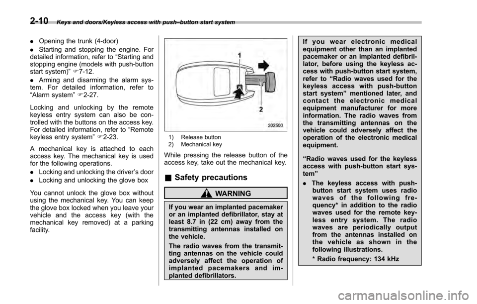
A mechanical key is attached to each
access key. The mechanical key is used
for the following operations.
. Locking and unlocking the driver ’s door
. Locking and unlocking the glove box
You cannot unlock the glove box without
using the mechanical key. You can keep
the glove box locked when you leave your
vehicle and the access key (with the
mechanical key removed) at a parking
facility.
1) Release button
2) Mechanical key
While pressing the release button of the
access key, take out the mechanical key.
& Safety precautions
WARNING
If you wear an implanted pacemaker
or an implanted defibrillator, stay at
least 8.7 in (22 cm) away from the
transmitting antennas installed on
the vehicle.
The radio waves from the transmit-
ting antennas on the vehicle could
adversely affect the operation of
implanted pacemakers and im-
planted defibrillators. If you wear electronic medical
equipment other than an implanted
pacemaker or an implanted defibril-
lator, before using the keyless ac-
cess with push-button start system,
refer to
“Radio waves used for the
keyless access with push-button
start system ”mentioned later, and
contact the electronic medical
equipment manufacturer for more
information. The radio waves from
the transmitting antennas on the
vehicle could adversely affect the
operation of the electronic medical
equipment.
“Radio waves used for the keyless
access with push-button start sys-
tem ”
. The keyless access with push-
button start system uses radio
waves of the following fre-
quency* in addition to the radio
waves used for the remote key-
less entry system. The radio
waves are periodically output
from the antennas installed on
the vehicle as shown in the
following illustrations.
* Radio frequency: 134 kHz
2-10
Page 114 of 594
.Carefully store the key number plate
supplied with the access key. It is
necessary for vehicle repair.
. Do not leave the access key in the
storage spaces inside the vehicle, such
as the door pocket, dashboard and the
corner of the cargo area. Vibrations
may damage the key or turn on the
switch, possibly resulting in a lockout.
. After the vehicle battery is dis-
charged or replaced, initialization of
the steering lock system may be re-
quired to start the engine. In this case,
perform the following procedure to
initialize the steering lock.
(1) Turn the push-button ignition
switch to the “OFF”position. For
details, refer to “Switching power ”
F 3-7.
(2) Open and close the driver ’s
door.
(3) Wait for approximately 10 sec-
onds.
When the steering is locked, the initi-
alization is completed.
. Do not leave the access key in the
following places.
–On the instrument panel
– On the floor
– Inside the glove box
– Inside the door trim pocket –
On the rear seat
– On the rear shelf (4-door)
– Inside the trunk (4-door)
– In the cargo area (5-door)
If you do, the following situations
may occur. – The access key is mistakenly
locked inside the vehicle.
– A false warning issues although
no malfunction actually occurs.
– No warning issues even when
any malfunction occurs.& Locking and unlocking with
“keyless access ”entry func-
tion
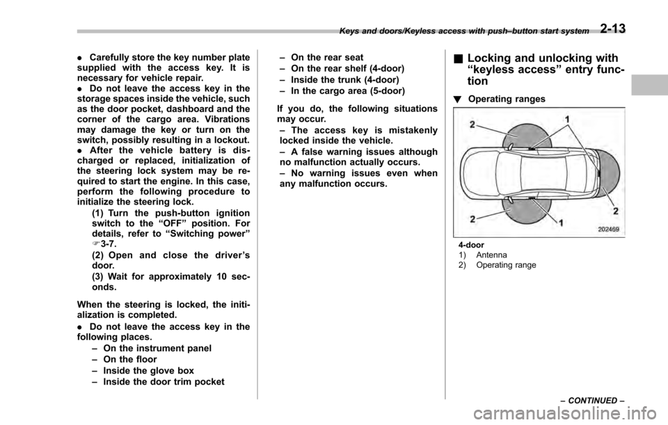
! Operating ranges
4-door
1) Antenna
2) Operating range
Keys and doors/Keyless access with push
–button start system
–CONTINUED –
2-13
Page 152 of 594
issue although no malfunction actually
occurs, or not to issue a warning when
any malfunction occurs.–On the instrument panel
– On the floor
– Inside the glove box
– Inside the door trim pocket
– On the rear seat
– On the rear shelf (4-door)
– Inside the trunk (4-door)
– In the cargo area (5-door)
. When operating the push-button
ignition switch or starting the engine,
if the access key battery is discharged,
perform the procedure described in
“Access key –if access key does not
operate properly ”F9-18. In such a
case, replace the battery immediately.
Refer to “Replacing battery of access
key” F11-44.& Switching power
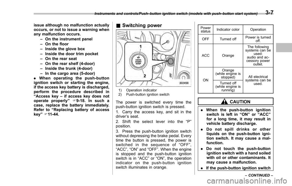
1) Operation indicator
2) Push-button ignition switch
The power is switched every time the
push-button ignition switch is pressed.
1. Carry the access key, and sit in the
driver ’s seat.
2. Shift the select lever into the “P ”
position.
3. Press the push-button ignition switch
without depressing the brake pedal. Every
time the button is pressed, the power is
switched in the sequence of “OFF ”,
“ACC ”, “ON ”and “OFF ”. When the engine
is stopped and the push-button ignition
switch is in “ACC”or “ON ”, the operation
indicator on the push-button ignition
switch illuminates in orange.
Power status Indicator color Operation
OFF Turned off Power is turned
off.
ACC Orange The following
systems can be used:
audio and ac-
cessory power
outlet.
ON Orange
(while engine is stopped) All electrical
systems can be
used.
Turned off
(while engine is
running)
CAUTION
.When the push-button ignition
switch is left in “ON ”or “ACC ”
for a long time, it may result in
vehicle battery discharge.
. Do not spill drinks or other
liquids on the push-button igni-
tion switch. It may cause a mal-
function.
. Do not touch the push-button
ignition switch with a hand soiled
with oil or other contaminants. It
may cause a malfunction.
. If the push-button ignition switch
Instruments and controls/Push –button ignition switch (models with push –button start system)
–CONTINUED –3-7
Page 270 of 594
&Replacing an air filter
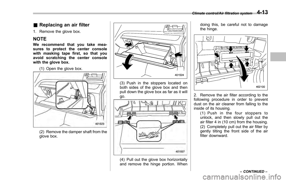
1. Remove the glove box.
NOTE
We recommend that you take mea-
sures to protect the center console
with masking tape first, so that you
avoid scratching the center console
with the glove box.
(1) Open the glove box.
(2) Remove the damper shaft from the
glove box.
(3) Push in the stoppers located on
both sides of the glove box and then
pull down the glove box as far as it will
go.
(4) Pull out the glove box horizontally
and remove the hinge portion. When doing this, be careful not to damage
the hinge.
2. Remove the air filter according to the
following procedure in order to prevent
dust on the air cleaner from falling to the
inside of its housing.
(1) Push in the four stoppers to
unlock, and then slowly pull out the
air filter 4 in (10 cm) from the housing.
(2) Completely pull out the air filter by
gently tilting the front side of the air
filter downward.
Climate control/Air filtration system
–CONTINUED –4-13
Page 271 of 594
Climate control/Air filtration system
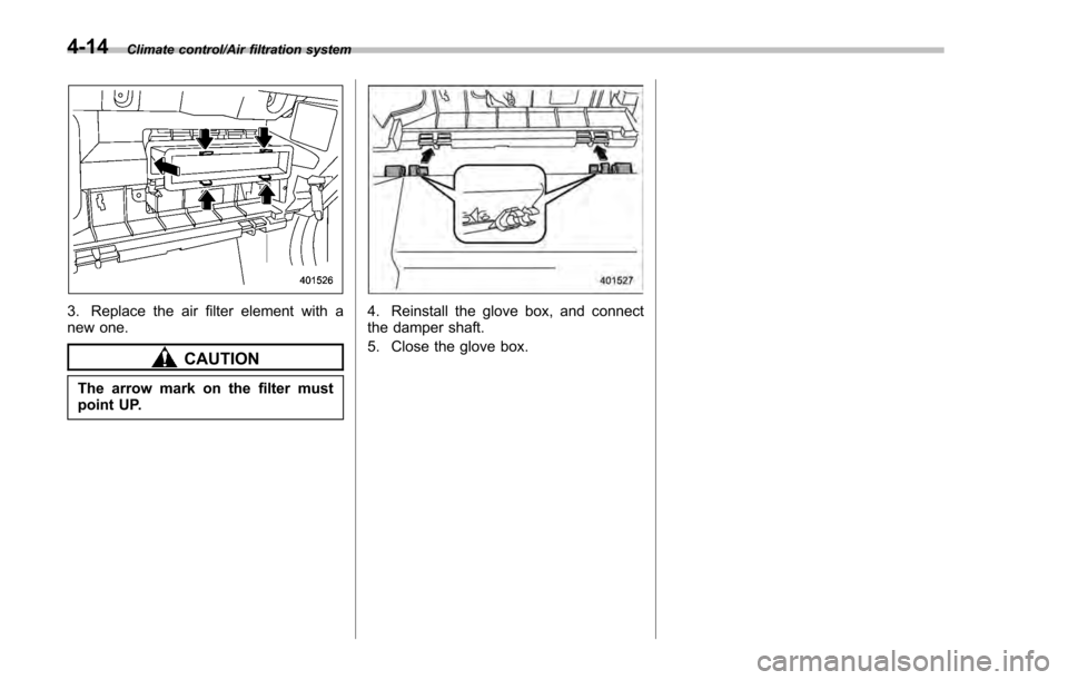
3. Replace the air filter element with a
new one.
CAUTION
The arrow mark on the filter must
point UP.
4. Reinstall the glove box, and connect
the damper shaft.
5. Close the glove box.
4-14