2016 SUBARU IMPREZA battery replacement
[x] Cancel search: battery replacementPage 102 of 594

Keys..................................................................... 2-3Key number plate ................................................ 2-3
Immobilizer.......................................................... 2-3Security indicator light ........................................ 2-4
Key replacement ................................................. 2-4
Certification for immobilizer system ..................... 2-4
Door locks........................................................... 2-5Locking and unlocking from the outside .. ............ 2-5
Locking and unlocking from the inside ................ 2-7
Battery drainage prevention function ................... 2-7
Power door locking switches............................. 2-8Key lock-in prevention function ........................... 2-9
Keyless access with push-button start
system (if equipped) ........................................ 2-9
Safety precautions............................................. 2-10
Locking and unlocking with “keyless access”
entry function. .................................................. 2-13
Selecting audible signal operation ...................... 2-18
Warning chimes and warning indicator ............... 2-18
Disabling keyless access function ...................... 2-18
When access key does not operate properly ....... 2-20
Replacing battery of access key ......................... 2-20
Replacing access key ......................................... 2-20
Certification for keyless access with push-button start system ..................................................... 2-20
PIN Code Access (models with “keyless
access with push-button start system ”)........ 2-21
Registering a PIN code ....................................... 2-22
Unlocking .......................................................... 2-23
Remote keyless entry system ........................... 2-23Locking the doors.............................................. 2-25 Unlocking the doors
.......................................... 2-25
Opening the trunk lid (4-door) .. .......................... 2-25
Unlocking the rear gate (5-door) ......................... 2-25
Vehicle finder function ....................................... 2-25
Sounding a panic alarm ..................................... 2-25
Selecting audible signal operation (models without “keyless access with push-button start
system ”).......................................................... 2-26
Replacing the battery ......................................... 2-26
Replacing lost transmitters ................................ 2-26
Certification for remote keyless entry system ..... 2-26
Alarm system..................................................... 2-27System operation ............................................... 2-28
Activating and deactivating the alarm system ..... 2-28
If you have accidentally triggered the alarm system ............................................................ 2-28
Arming the system ............................................ 2-29
Disarming the system ........................................ 2-32
Valet mode ........................................................ 2-32
Passive arming (models without “keyless access
with push-button start system ”) ....................... 2-32
Tripped sensor identification .............................. 2-34
Shock sensors (dealer option).. .......................... 2-34
Child safety locks.............................................. 2-35
Windows ............................................................. 2-35
Power window operation by driver ..................... 2-35
Power window operation by passengers ............. 2-37
Initialization of power window .. .......................... 2-38
Trunk lid (4-door)............................................... 2-38To open and close the trunk lid from outside . ..... 2-39
To open the trunk lid from inside. ....................... 2-39
Keys and doors
2
Page 112 of 594

4-door
1) Antenna5-door
1) Antenna
CAUTION
.Never leave or store the access
key inside the vehicle or within 6.6 ft (2 m) around the vehicle (e.
g., in the garage). The access key
may be locked inside the vehicle,
or the battery may discharge
rapidly.
. The access key contains electro-
nic components. Observe the
following precautions to prevent
malfunctions.
– Although you can replace the
battery of the access key
yourself, it is recommended
that the battery be replaced by
a SUBARU dealer to avoid the
risk of damage at the time of
replacement.
– Do not get the access key wet.
If the access key gets wet,
wipe it off immediately and let
it dry completely.
– Do not apply strong impacts
to the access key.
– Keep the access key away
from magnetic sources.
– Never leave the access key in
direct sunlight or anywhere
that may become hot, such
as on the dashboard. It may
damage the battery or cause
circuit malfunctions.
Keys and doors/Keyless access with push –button start system
–CONTINUED –2-11
Page 137 of 594

Keys and doors/Windows
!Operating the driver ’s window
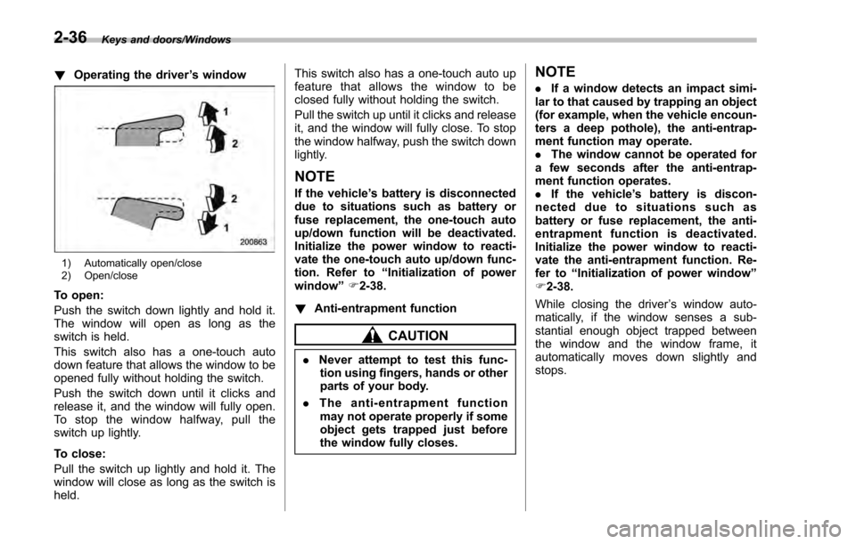
1) Automatically open/close
2) Open/close
To open:
Push the switch down lightly and hold it.
The window will open as long as the
switch is held.
This switch also has a one-touch auto
down feature that allows the window to be
opened fully without holding the switch.
Push the switch down until it clicks and
release it, and the window will fully open.
To stop the window halfway, pull the
switch up lightly.
To close:
Pull the switch up lightly and hold it. The
window will close as long as the switch is
held. This switch also has a one-touch auto up
feature that allows the window to be
closed fully without holding the switch.
Pull the switch up until it clicks and release
it, and the window will fully close. To stop
the window halfway, push the switch down
lightly.
NOTE
If the vehicle
’s battery is disconnected
due to situations such as battery or
fuse replacement, the one-touch auto
up/down function will be deactivated.
Initialize the power window to reacti-
vate the one-touch auto up/down func-
tion. Refer to “Initialization of power
window ”F 2-38.
! Anti-entrapment function
CAUTION
.Never attempt to test this func-
tion using fingers, hands or other
parts of your body.
. The anti-entrapment function
may not operate properly if some
object gets trapped just before
the window fully closes.
NOTE
. If a window detects an impact simi-
lar to that caused by trapping an object
(for example, when the vehicle encoun-
ters a deep pothole), the anti-entrap-
ment function may operate.
. The window cannot be operated for
a few seconds after the anti-entrap-
ment function operates.
. If the vehicle ’s battery is discon-
nected due to situations such as
battery or fuse replacement, the anti-
entrapment function is deactivated.
Initialize the power window to reacti-
vate the anti-entrapment function. Re-
fer to “Initialization of power window ”
F 2-38.
While closing the driver ’s window auto-
matically, if the window senses a sub-
stantial enough object trapped between
the window and the window frame, it
automatically moves down slightly and
stops.
2-36
Page 139 of 594

Keys and doors/Trunk lid (4–door)
! Operating the windows
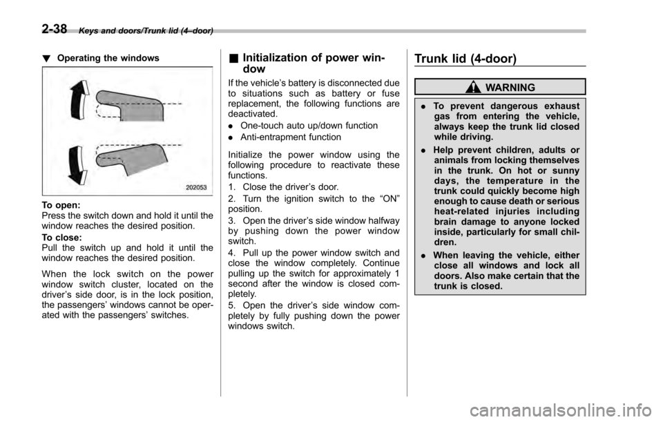
To open:
Press the switch down and hold it until the
window reaches the desired position.
To close:
Pull the switch up and hold it until the
window reaches the desired position.
When the lock switch on the power
window switch cluster, located on the
driver ’s side door, is in the lock position,
the passengers’ windows cannot be oper-
ated with the passengers’ switches.
&Initialization of power win-
dow
If the vehicle’ s battery is disconnected due
to situations such as battery or fuse
replacement, the following functions are
deactivated.
. One-touch auto up/down function
. Anti-entrapment function
Initialize the power window using the
following procedure to reactivate these
functions.
1. Close the driver ’s door.
2. Turn the ignition switch to the “ON ”
position.
3. Open the driver ’s side window halfway
by pushing down the power window
switch.
4. Pull up the power window switch and
close the window completely. Continue
pulling up the switch for approximately 1
second after the window is closed com-
pletely.
5. Open the driver ’s side window com-
pletely by fully pushing down the power
windows switch.
Trunk lid (4-door)
WARNING
. To prevent dangerous exhaust
gas from entering the vehicle,
always keep the trunk lid closed
while driving.
. Help prevent children, adults or
animals from locking themselves
in the trunk. On hot or sunny
days, the temperature in the
trunk could quickly become high
enough to cause death or serious
heat-related injuries including
brain damage to anyone locked
inside, particularly for small chil-
dren.
. When leaving the vehicle, either
close all windows and lock all
doors. Also make certain that the
trunk is closed.
2-38
Page 156 of 594

&Double trip meter
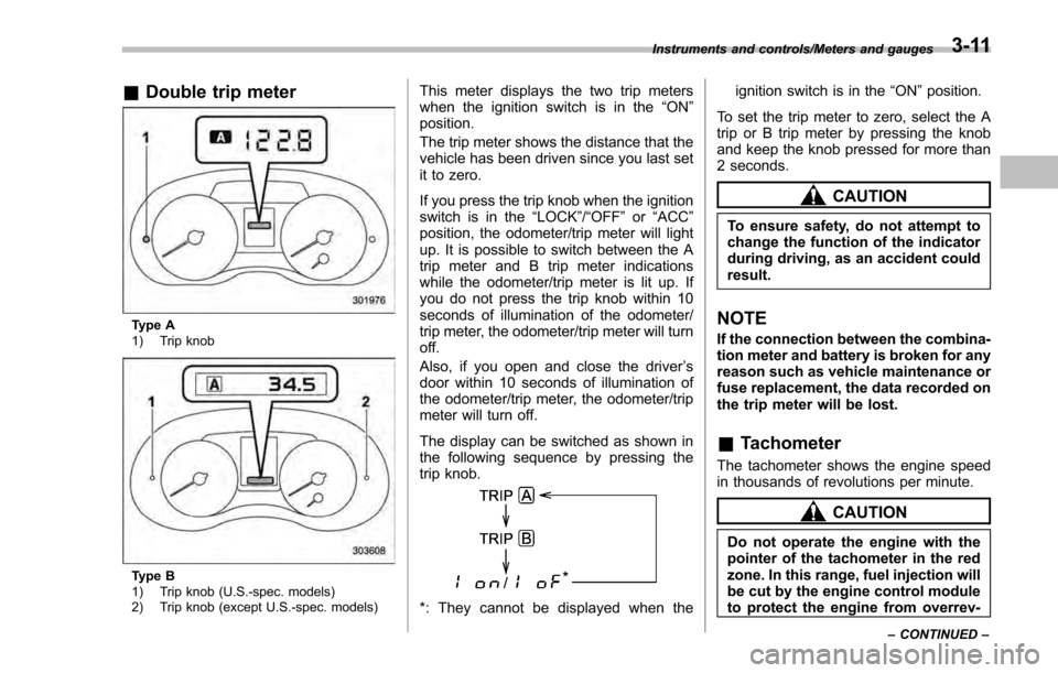
Type A
1) Trip knob
Type B
1) Trip knob (U.S.-spec. models)
2) Trip knob (except U.S.-spec. models)
This meter displays the two trip meters
when the ignition switch is in the “ON”
position.
The trip meter shows the distance that the
vehicle has been driven since you last set
it to zero.
If you press the trip knob when the ignition
switch is in the “LOCK”/ “OFF”or “ACC ”
position, the odometer/trip meter will light
up. It is possible to switch between the A
trip meter and B trip meter indications
while the odometer/trip meter is lit up. If
you do not press the trip knob within 10
seconds of illumination of the odometer/
trip meter, the odometer/trip meter will turn
off.
Also, if you open and close the driver ’s
door within 10 seconds of illumination of
the odometer/trip meter, the odometer/trip
meter will turn off.
The display can be switched as shown in
the following sequence by pressing the
trip knob.
*: They cannot be displayed when the ignition switch is in the
“ON ”position.
To set the trip meter to zero, select the A
trip or B trip meter by pressing the knob
and keep the knob pressed for more than
2 seconds.
CAUTION
To ensure safety, do not attempt to
change the function of the indicator
during driving, as an accident could
result.
NOTE
If the connection between the combina-
tion meter and battery is broken for any
reason such as vehicle maintenance or
fuse replacement, the data recorded on
the trip meter will be lost.
& Tachometer
The tachometer shows the engine speed
in thousands of revolutions per minute.
CAUTION
Do not operate the engine with the
pointer of the tachometer in the red
zone. In this range, fuel injection will
be cut by the engine control module
to protect the engine from overrev-
Instruments and controls/Meters and gauges
–CONTINUED –3-11
Page 182 of 594

!Turn off display of driving informa-
tion display
The driving information display can be
turned off.
To turn off the display, turn the ignition
switch to the “LOCK”/“OFF ”position and
press the “+ ” button adjacent to the clock
display for approximately 5 seconds.
Then, the driving information display and
the clock display will blink for 3 seconds to
notify you that the driving information
display has been turned off.
To restore the driving information display,
once again press the “+ ” button for
approximately 5 seconds.
NOTE
. The initial display setting of the
driving information display has been
set to operational at the time of ship-
ment from the factory.
. The average fuel consumption and
average vehicle speed are calculated
even while the driving information dis-
play is not displayed.
. Evenifyouturnoffthedriving
information display, the display will
automatically turn on when the battery
voltage is disconnected and then re-
connected for battery replacement or
fuse replacement.
& Clock
To adjust the time shown by the clock,
press the “+”button or “−”button. If you
press the “+”button, the indicated time will
change in one-minute increments. If you
press the “−”button, the indicated time will
change in one-minute decrements. If you
keep the button pressed, the rate at which
the indicated time changes will speed up.
The clock can be set to 12-hour or 24-hour
clock displays. Perform the following
procedure to switch the display format.
1. Place the ignition switch in the
“LOCK”/ “OFF ”position.
2. Press and hold the “−”button that is
located near the clock display for approxi-
mately 5 seconds. The clock display will
then start to flash. 3. While the clock display is flashing,
press and hold the
“+”button for approxi-
mately 2 seconds. The clock format will
then change.
4. The clock display will continue to flash
for approximately 3 seconds to inform you
that the clock display has been changed.
If you want to change the clock display
again, press and hold the “+”button for
approximately 2 seconds while the clock
display is flashing.
Instruments and controls/Information display3-37
Page 405 of 594

Starting and operating/Remote engine start system (dealer option)
ing to the following procedure.
1. Open the driver’s door (the driver ’s
door must remain opened throughout the
entire process).
2. Depress and hold the brake pedal.
3. Turn the ignition switch to “ON”then
“LOCK” /“OFF ”, back to “ON”then “LOCK”/
“OFF ”, back to “ON”then “LOCK” /“OFF ”,
then back to “ON”again and leave the
ignition “ON”throughout the programming
process.
4. The system will flash the side marker
lights, tail lights and parking lights and
honk the horn three times, indicating that
the system has entered the transmitter
learn mode.
5. Press and release the “
”button on
the transmitter that you want to program.
6. The system will flash the side marker
lights, tail lights and parking lights and
honk the horn one time, indicating that the
system has learned the transmitter. Upon
successful programming, the remote start
confirmation transmitter button will flash
one time.
7. Repeat step 5 for any additional
transmitters (the system will accept up to
eight transmitters).
8. The system will exit the transmitter
learn mode if the key is turned to the
“LOCK”/ “OFF ”position, the door is closed or after 2 minutes.
&
System maintenance
NOTE
For models without “keyless access
with push-button start system”:
In the event that the vehicle ’s battery is
replaced, discharged or disconnected,
it will be necessary to start the vehicle
a minimum of one time using the key
prior to activating the remote engine
start system. This is required to allow
the vehicle electronic systems to re-
synchronize.
! Changing the batteries
CAUTION
.Do not let dust, oil or water get on
or in the remote engine start
transmitter when replacing the
battery.
. Be careful not to damage the
printed circuit board in the re-
mote engine start transmitter
when replacing the battery.
. Be careful not to allow children to
touch the battery and any re-
moved parts; children could
swallow them. .
There is a danger of explosion if
an incorrect replacement battery
is used. Replace only with the
same or equivalent type of bat-
tery.
. Batteries should not be exposed
to excessive heat such as sun-
shine, fire or the like.
For models with “keyless access with
push-button start system ”:
Perform the procedure described in “Re-
placing battery of access key ”F 11-44.
For models without “keyless access
with push-button start system”:
The two 3-volt lithium batteries (model
CR-2032) supplied in your remote engine
start transmitter should last approximately
one year, depending on usage. When the
batteries begin to weaken, you will notice
a decrease in range (distance from the
vehicle that your remote control operates).
Follow the instructions below to change
the remote engine start transmitter bat-
teries.
7-20
Page 442 of 594

nation meter, and the BSD/RCTA is
deactivated.
Press the switch again to activate the
BSD/RCTA. The BSD/RCTA OFF indica-
tor will disappear.
NOTE
.In the following cases, the system
may not operate properly due to
blocked radar waves. Press the BSD/
RCTA OFF switch to deactivate the
system.
–When towing a trailer
– When a bicycle carrier or other
item is fitted to the rear of the
vehicle
– When using a chassis dynam-
ometer or free roller device, etc.
– When running the engine and
makingthewheelsrotatewhile
lifting up the vehicle
. If the ignition switch is turned to the
“LOCK ”/“OFF ”position, the last known
status of the system is maintained. For
example, if the ignition switch is turned
to the “LOCK ”/“OFF ”position with the
BSD/RCTA deactivated, the BSD/RCTA
will remain deactivated the next time
the ignition switch is turned to the
“ON ”position.
. If the vehicle battery is disconnected
due to situations such as battery terminal or fuse replacement, after the
battery is reconnected, the BSD/RCTA
will be activated.
&
Certification for the BSD/
RCTA
FCC ID: OAYSRR2A
CAUTION
FCC WARNING
Changes or modifications not ex-
pressly approved by the party re-
sponsible for compliance could void
the user ’s authority to operate the
equipment.
This device complies with part 15 of the
FCC Rules. Operation is subject to the
following two conditions: (1) This device
may not cause harmful interference, and
(2) this device must accept any interfer-
ence received, including interference that
may cause undesired operation.
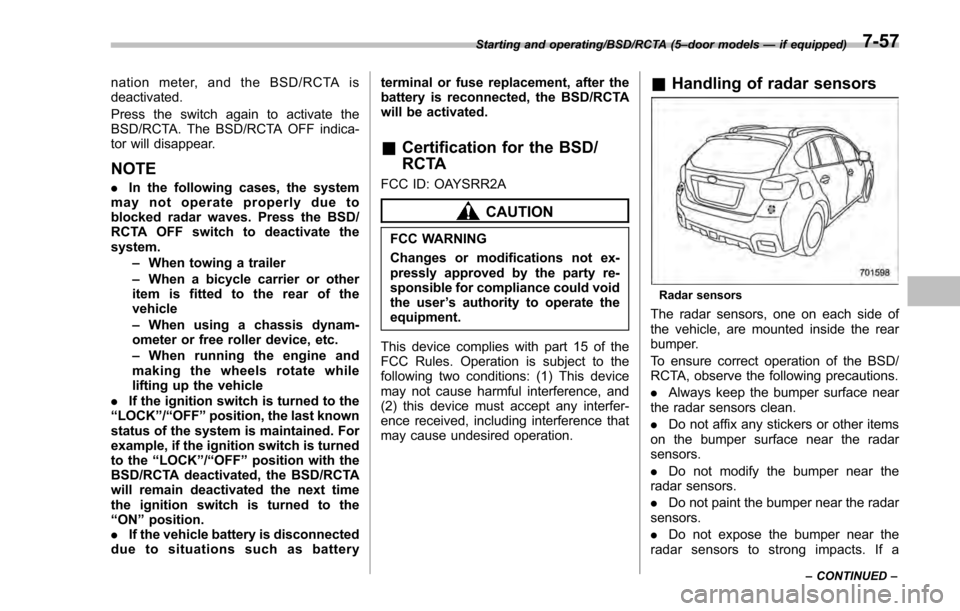
& Handling of radar sensors
Radar sensors
The radar sensors, one on each side of
the vehicle, are mounted inside the rear
bumper.
To ensure correct operation of the BSD/
RCTA, observe the following precautions.
. Always keep the bumper surface near
the radar sensors clean.
. Do not affix any stickers or other items
on the bumper surface near the radar
sensors.
. Do not modify the bumper near the
radar sensors.
. Do not paint the bumper near the radar
sensors.
. Do not expose the bumper near the
radar sensors to strong impacts. If a
Starting and operating/BSD/RCTA (5 –door models —if equipped)
–CONTINUED –7-57