2016 SUBARU IMPREZA fuse
[x] Cancel search: fusePage 19 of 594

&Instrument panel1) Illumination brightness control
(page 3-93)
2) Vehicle Dynamics Control OFF switch (page 7-36)
3) Combination meter (page 3-9)
4) Information display (page 3-32)/Multi function display (page 3-42)
5) Hazard warning flasher switch (models with multi function display) (page 3-8)
6) Hazard warning flasher switch (models without multi function display) (page 3-8)
7) Multi function display control switches (page 3-42)
8) Audio (page 5-1)
9) Climate control (page 4-1)
10) Tilt/telescopic steering (page 3-110)
11) Fuse box (page 11-35)
12) Hood lock release knob (page 11-5)
13) BSD/RCTA OFF switch (page 7-50)
14) Steering responsive fog lights OFF switch (page 3-95)
NOTE
For models with the EyeSight system:
Refer to the Owner ’s Manual supple-
ment for the EyeSight system.
14
Page 137 of 594
Keys and doors/Windows
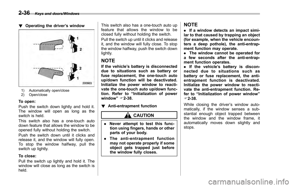
!Operating the driver ’s window
1) Automatically open/close
2) Open/close
To open:
Push the switch down lightly and hold it.
The window will open as long as the
switch is held.
This switch also has a one-touch auto
down feature that allows the window to be
opened fully without holding the switch.
Push the switch down until it clicks and
release it, and the window will fully open.
To stop the window halfway, pull the
switch up lightly.
To close:
Pull the switch up lightly and hold it. The
window will close as long as the switch is
held. This switch also has a one-touch auto up
feature that allows the window to be
closed fully without holding the switch.
Pull the switch up until it clicks and release
it, and the window will fully close. To stop
the window halfway, push the switch down
lightly.
NOTE
If the vehicle
’s battery is disconnected
due to situations such as battery or
fuse replacement, the one-touch auto
up/down function will be deactivated.
Initialize the power window to reacti-
vate the one-touch auto up/down func-
tion. Refer to “Initialization of power
window ”F 2-38.
! Anti-entrapment function
CAUTION
.Never attempt to test this func-
tion using fingers, hands or other
parts of your body.
. The anti-entrapment function
may not operate properly if some
object gets trapped just before
the window fully closes.
NOTE
. If a window detects an impact simi-
lar to that caused by trapping an object
(for example, when the vehicle encoun-
ters a deep pothole), the anti-entrap-
ment function may operate.
. The window cannot be operated for
a few seconds after the anti-entrap-
ment function operates.
. If the vehicle ’s battery is discon-
nected due to situations such as
battery or fuse replacement, the anti-
entrapment function is deactivated.
Initialize the power window to reacti-
vate the anti-entrapment function. Re-
fer to “Initialization of power window ”
F 2-38.
While closing the driver ’s window auto-
matically, if the window senses a sub-
stantial enough object trapped between
the window and the window frame, it
automatically moves down slightly and
stops.
2-36
Page 139 of 594
Keys and doors/Trunk lid (4–door)
! Operating the windows
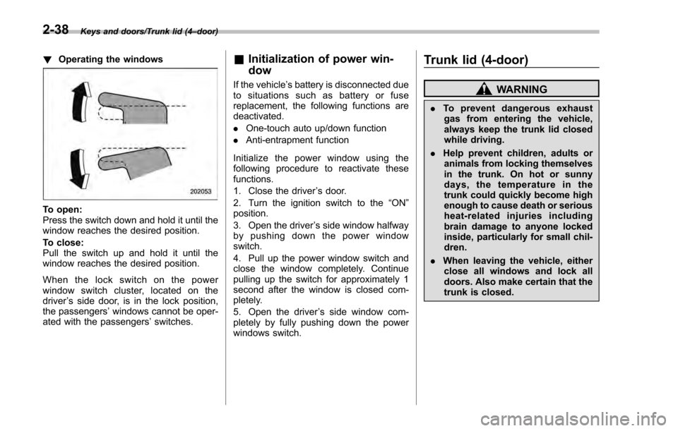
To open:
Press the switch down and hold it until the
window reaches the desired position.
To close:
Pull the switch up and hold it until the
window reaches the desired position.
When the lock switch on the power
window switch cluster, located on the
driver ’s side door, is in the lock position,
the passengers’ windows cannot be oper-
ated with the passengers’ switches.
&Initialization of power win-
dow
If the vehicle’ s battery is disconnected due
to situations such as battery or fuse
replacement, the following functions are
deactivated.
. One-touch auto up/down function
. Anti-entrapment function
Initialize the power window using the
following procedure to reactivate these
functions.
1. Close the driver ’s door.
2. Turn the ignition switch to the “ON ”
position.
3. Open the driver ’s side window halfway
by pushing down the power window
switch.
4. Pull up the power window switch and
close the window completely. Continue
pulling up the switch for approximately 1
second after the window is closed com-
pletely.
5. Open the driver ’s side window com-
pletely by fully pushing down the power
windows switch.
Trunk lid (4-door)
WARNING
. To prevent dangerous exhaust
gas from entering the vehicle,
always keep the trunk lid closed
while driving.
. Help prevent children, adults or
animals from locking themselves
in the trunk. On hot or sunny
days, the temperature in the
trunk could quickly become high
enough to cause death or serious
heat-related injuries including
brain damage to anyone locked
inside, particularly for small chil-
dren.
. When leaving the vehicle, either
close all windows and lock all
doors. Also make certain that the
trunk is closed.
2-38
Page 156 of 594
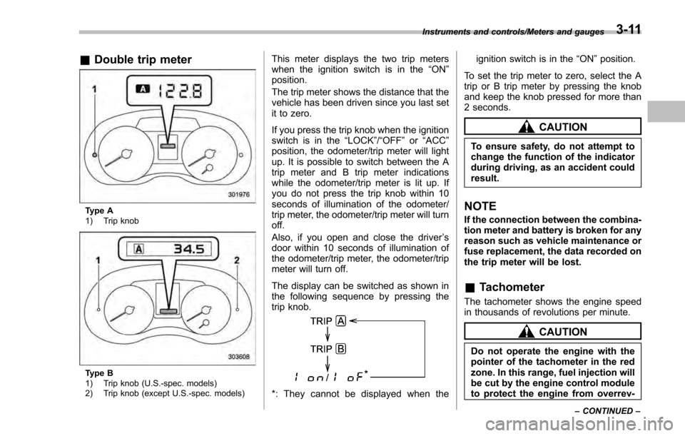
&Double trip meter
Type A
1) Trip knob
Type B
1) Trip knob (U.S.-spec. models)
2) Trip knob (except U.S.-spec. models)
This meter displays the two trip meters
when the ignition switch is in the “ON”
position.
The trip meter shows the distance that the
vehicle has been driven since you last set
it to zero.
If you press the trip knob when the ignition
switch is in the “LOCK”/ “OFF”or “ACC ”
position, the odometer/trip meter will light
up. It is possible to switch between the A
trip meter and B trip meter indications
while the odometer/trip meter is lit up. If
you do not press the trip knob within 10
seconds of illumination of the odometer/
trip meter, the odometer/trip meter will turn
off.
Also, if you open and close the driver ’s
door within 10 seconds of illumination of
the odometer/trip meter, the odometer/trip
meter will turn off.
The display can be switched as shown in
the following sequence by pressing the
trip knob.
*: They cannot be displayed when the ignition switch is in the
“ON ”position.
To set the trip meter to zero, select the A
trip or B trip meter by pressing the knob
and keep the knob pressed for more than
2 seconds.
CAUTION
To ensure safety, do not attempt to
change the function of the indicator
during driving, as an accident could
result.
NOTE
If the connection between the combina-
tion meter and battery is broken for any
reason such as vehicle maintenance or
fuse replacement, the data recorded on
the trip meter will be lost.
& Tachometer
The tachometer shows the engine speed
in thousands of revolutions per minute.
CAUTION
Do not operate the engine with the
pointer of the tachometer in the red
zone. In this range, fuel injection will
be cut by the engine control module
to protect the engine from overrev-
Instruments and controls/Meters and gauges
–CONTINUED –3-11
Page 175 of 594
Instruments and controls/Warning and indicator lights
&Security indicator light
This indicator light shows the status of the
alarm system. It also indicates operation
of the immobilizer system.
!Alarm system
It blinks to show the driver the operational
status of the alarm system. For detailed
information, refer to “Alarm system ”F 2-
27.
! Immobilizer system
The security indicator light starts blinking
in the following conditions.
For models with “keyless access with
push-button start system ”:
. Immediately after the push-button igni-
tion switch is turned to the “OFF”position.
. Immediately after the driver ’s door is
opened or closed when all of the following
conditions are met.
–The push-button ignition switch is in
the “ON ”or “ACC ”position.
– The access key is outside the
vehicle.
– The engine is not running.
In the event that the push-button ignition
switch is pressed to turn it on or to start
the engine carrying an unauthorized key
(for example, the key is unregistered or
the ID code does not match), the power is not switched to
“ON ”and the security
indicator light continues blinking.
For models without “keyless access
with push-button start system ”:
. Approximately 60 seconds after the
ignition switch is turned from the “ON ”
position to the “ACC”or “LOCK ”position.
. Immediately after the key is pulled out.
If the indicator light does not blink in the
above conditions, it may indicate that
immobilizer system may be malfunction-
ing. Contact your nearest SUBARU dealer
immediately.
In the event that an unauthorized key (for
example, an unauthorized duplicate) is
used to start the engine, the security
indicator light illuminates. For details
about the immobilizer system, refer to
“Immobilizer ”F 2-3.
NOTE
. The security indicator light remains
off in the following conditions. This is
normal and does not indicate a mal-
function.
–while the engine is running
– for approximately 60 seconds
after the ignition switch is turned
from the “ON ”position to the
“ACC ”or “LOCK ”/“OFF ”position
. Even if the security indicator light blinks irregularly or its fuse blows (the
light does not blink if its fuse is blown),
the immobilizer system will function
normally.
&
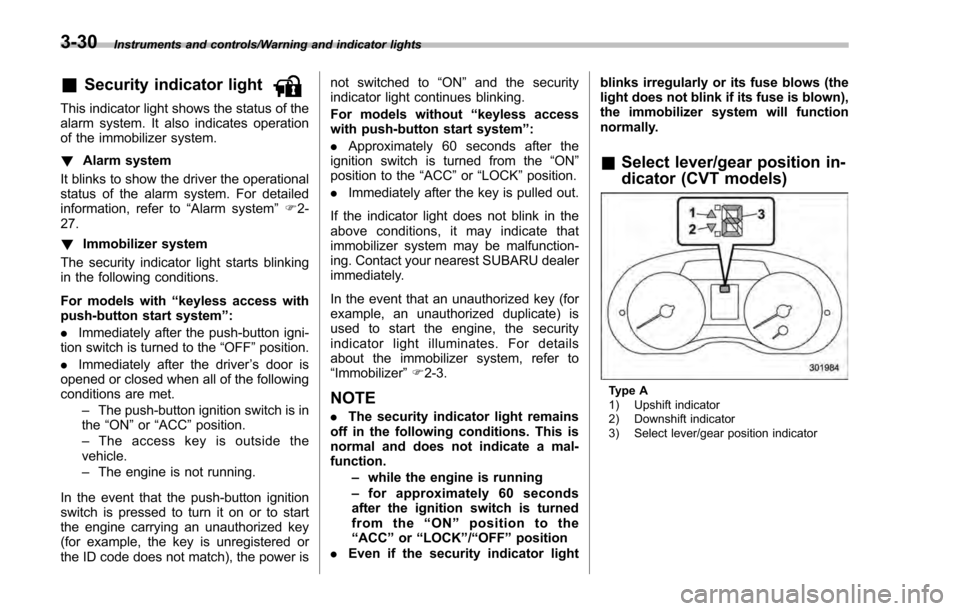
Select lever/gear position in-
dicator (CVT models)
Type A
1) Upshift indicator
2) Downshift indicator
3) Select lever/gear position indicator
3-30
Page 182 of 594

!Turn off display of driving informa-
tion display
The driving information display can be
turned off.
To turn off the display, turn the ignition
switch to the “LOCK”/“OFF ”position and
press the “+ ” button adjacent to the clock
display for approximately 5 seconds.
Then, the driving information display and
the clock display will blink for 3 seconds to
notify you that the driving information
display has been turned off.
To restore the driving information display,
once again press the “+ ” button for
approximately 5 seconds.
NOTE
. The initial display setting of the
driving information display has been
set to operational at the time of ship-
ment from the factory.
. The average fuel consumption and
average vehicle speed are calculated
even while the driving information dis-
play is not displayed.
. Evenifyouturnoffthedriving
information display, the display will
automatically turn on when the battery
voltage is disconnected and then re-
connected for battery replacement or
fuse replacement.
& Clock
To adjust the time shown by the clock,
press the “+”button or “−”button. If you
press the “+”button, the indicated time will
change in one-minute increments. If you
press the “−”button, the indicated time will
change in one-minute decrements. If you
keep the button pressed, the rate at which
the indicated time changes will speed up.
The clock can be set to 12-hour or 24-hour
clock displays. Perform the following
procedure to switch the display format.
1. Place the ignition switch in the
“LOCK”/ “OFF ”position.
2. Press and hold the “−”button that is
located near the clock display for approxi-
mately 5 seconds. The clock display will
then start to flash. 3. While the clock display is flashing,
press and hold the
“+”button for approxi-
mately 2 seconds. The clock format will
then change.
4. The clock display will continue to flash
for approximately 3 seconds to inform you
that the clock display has been changed.
If you want to change the clock display
again, press and hold the “+”button for
approximately 2 seconds while the clock
display is flashing.
Instruments and controls/Information display3-37
Page 381 of 594
Interior equipment/Rear view camera
.Since the range of the image on
the monitor is limited, you should
always check the rear view and
the surrounding area with your
eyes and mirrors, and move
backward at a slow speed. Mov-
ing backward only by checking
the rear view image from the
camera could cause an accident.
. Do not disassemble or modify the
camera, switch or wiring. If
smoke comes out or you smell
a strange odor, stop using the
rear view camera immediately.
Contact your SUBARU dealer
for an inspection. Continued use
may result in accident, fire or
electric shock.
CAUTION
. If your vehicle is washed with a
high-pressure washer, do not
allow water to contact the camera
directly. Entry of water in the
camera lens may result in con-
densation, malfunction, fire or
electric shock.
. Since the camera is a precision
device, do not subject it to strong
impacts. Otherwise, malfunction, fire or electric shock may occur.
. If mud or snow sticks to or is
frozen on the camera, you must
be very careful when removing it.
Otherwise, damage to the camera
may cause a fire or electric
shock. Pour water or lukewarm
water over the camera to remove
mud and ice, and wipe it with a
soft, dry cloth.
. Do not put a flame close to the
camera or wiring. Otherwise, da-
mage or fire may occur.
. When replacing the fuse, be sure
to use a fuse with the specified
rating. Use of a fuse with a
different rating may result in a
malfunction.
. If the rear view camera is used for
a long time while the engine is
not operated, the battery may
become completely discharged.
NOTE
. Do not wipe the camera with alcohol,
benzine or paint thinner. Otherwise,
discoloration may occur. To remove
contamination, wipe the camera with a
cloth moistened with a diluted neutral
detergent and then wipe it with a soft, dry cloth.
.
When waxing the vehicle, be careful
not to apply the wax to the camera. If it
comes in contact with the camera,
moisten a clean cloth with a diluted
neutral detergent to remove the wax.
. The camera lens has a hard coating
to help prevent scratches. However,
when washing the vehicle or cleaning
the camera lens, be careful not to
scratch the camera lens. Do not use a
washing brush directly on the camera
lens. The image quality of the rear view
camera may deteriorate.
. Strong light shined on the camera
lens may develop vertical lines around
the light source. This is not a malfunc-
tion.
. Under fluorescent light, the display
may flicker. However, this is not a
malfunction.
. The image of the rear view camera
may be slightly different from the
actual color of the objects.
6-16
Page 395 of 594

Starting and operating/Starting and stopping the engine (models without push–button start system)
. When starting the engine, be sure
to sit in the driver ’s seat (except
when using the remote engine
start system).
NOTE
. Avoid rapid racing and rapid accel-
eration immediately after the engine
has started.
. For a short time after the engine has
started, the engine speed is kept high.
When the warm-up is completed, the
engine speed lowers automatically.
. On rare occasions, it may be difficult
to start the engine depending on the
fuel and the usage condition (repeated
driving of a distance in which the
engine has not warmed up sufficiently).
In such a case, it is recommended that
you change to a different brand of fuel.
. On rare occasions, transient knock-
ing may be heard from the engine when
the accelerator is operated rapidly
such as a rapid start-up and a rapid
acceleration. This is not a malfunction.
. The engine starts more easily when
the headlights, air conditioner and rear
window defogger are turned off.
. After the engine starts, the engine
speed will be kept high until the engine
has warmed up sufficiently. !
MT models
1. Apply the parking brake.
2. Turn off unnecessary lights and ac-
cessories.
3. Depress the clutch pedal to the floor
and shift the shift lever into neutral. Hold
the clutch pedal to the floor while starting
the engine.
The starter motor will only operate when
the clutch pedal is depressed fully to the
floor.
4. Turn the ignition switch to the “ON”
position and check the operation of the
warning and indicator lights. Refer to
“Warning and indicator lights ”F 3-13.
5. Turn the ignition switch to the “START”
position without depressing the accelera-
tor pedal. Release the key immediately
after the engine has started.
If the engine does not start, try the
following procedure.
(1) Turn the ignition switch to the
“LOCK” /“OFF ”position and wait for at
least 10 seconds. After checking that
the parking brake is firmly set, turn the
ignition switch to the “START”position
while depressing the accelerator pedal
slightly (approximately a quarter of the
full stroke). Release the accelerator
pedal as soon as the engine starts.
(2) If this fails to start the engine, turn the ignition switch back to the
“LOCK”/
“ OFF ”position and wait for at least 10
seconds. Then fully depress the accel-
erator pedal and turn the ignition
switch to the “START”position. If the
engine starts, quickly release the
accelerator pedal.
(3) If this fails to start the engine, turn
the ignition switch again to the
“LOCK ”/“OFF ”position. After waiting
for 10 seconds or longer, turn the
ignition switch to the “START ”position
without depressing the accelerator
pedal.
(4) If the engine still refuses to start,
contact your nearest SUBARU dealer
for assistance.
6. Confirm that all warning and indicator
lights have turned off after the engine has
started. The fuel injection system auto-
matically lowers the idle speed as the
engine warms up.
! CVT models
1. Apply the parking brake.
2. Turn off unnecessary lights and ac-
cessories.
3. Shift
the select lever to the “P”or “N”
position (preferably the “P ”position).
The starter motor will only operate when
the select lever is at the “P ”or “N”position.
7-10