2016 SUBARU IMPREZA turn signal
[x] Cancel search: turn signalPage 22 of 594

&Light control and wiper control levers/switches1) Windshield wiper (page 3-96)
2) Mist (page 3-97)
3) Windshield washer (page 3-98)
4) Rear window wiper and washer switch
(page 3-99)
5) Wiper intermittent time control switch (page 3-98)
6) Wiper control lever (page 3-97)
7) Light control switch (page 3-89)
8) Fog light switch (page 3-94)
9) Headlight ON/OFF/AUTO (page 3-89)
10) Headlight flasher High/Low beam change (page 3-91)
11) Turn signal lever (page 3-92)
–CONTINUED –
17
Page 27 of 594

&Warning and indicator lights
Mark Name Page
Seatbelt warning light 3-14
Front passenger’s
seatbelt warning light 3-14
SRS airbag system
warning light3-15
/Front passenger
’s
frontal airbag ON indi-
cator 3-16
/Front passenger
’s
frontal airbag OFF in-
dicator 3-16
CHECK ENGINE
warning light/Malfunc-
tion indicator light3-16
Coolant temperature
low indicator light/
Coolant temperature
high warning light3-17
Charge warning light 3-18
Oil pressure warning
light
3-18
Engine oil level warn-
ing light3-18Mark Name Page
AT OIL TEMP warning
light (CVT models)
3-19
ABS warning light 3-21
Brake system warning
light
3-21
Door open warning
light3-23
AWD warning light
(CVT models)
3-23
Power steering warn-
ing light3-23
Hill start assist warn-
ing light/Hill start assist
OFF indicator light3-22
Vehicle Dynamics
Control warning light/
Vehicle Dynamics
Control operation indi-
cator light3-24
Vehicle Dynamics
Control OFF indicator
light
3-25
Turn signal indicator
lights
3-31Mark Name Page
High beam indicator
light
3-31
Automatic headlight
beam leveler warning
light (if equipped)3-31
Front fog light indicator
light (if equipped)
3-31
Access key warning
indicator (if equipped)3-25
Security indicator light 3-30
Headlight indicator
light (if equipped)
3-32
Cruise control indica-
tor light (if equipped)3-31
Cruise control set in-
dicator light (if
equipped)3-31
Low fuel warning light 3-22
Low tire pressure
warning light
(U.S.-spec. models)3-19
Windshield washer
fluid warning light
3-19
22
Page 116 of 594

less equipment is used), or while talking
on a cell phone, the operating ranges may
be reduced, or the keyless access func-
tion may not operate.
In such a case, perform the procedure
described in“Locking and unlocking ”F 9-
18.
. When an access key is in the operating
range, if the door handle becomes wet
due to exposure to a significant amount of
water when the vehicle is washed or
during heavy rain, the doors may be
locked or unlocked.
. The keyless access function may not
operate properly depending on the status
of the access key and the radio wave
conditions around the vehicle. In such a
case, perform the procedure described in
“Locking and unlocking ”F 9-18.
! How to use keyless access func-
tions
! Keyless access function tips
. When you lock the doors and rear gate
(5-door) using the keyless access func-
tion, turn the push-button ignition switch
off. It is not possible to lock the doors and
rear gate using the keyless access func-
tion when the push-button ignition switch
is on the “ACC ”or “ON ”position. Refer to
“Switching power ”F 3-7.
. If the door handle is gripped with a gloved hand, the door lock may not be
released.
.
If the door lock sensor is touched three
times or more repeatedly, the system will
ignore the sensor operation.
. When performing the locking proce-
dure too quickly, locking may not have
been completed. After performing the
locking procedure, it is recommended to
pull the REAR door handle to confirm that
the doors have been locked.
. It is possible to lock the doors even
when one of the doors is open. After
performing the locking procedure, close
the opened door or rear gate to lock it.
. Within 3 seconds after locking the
doors and the rear gate by using the
keyless access function, it is not possible
to unlock doors and/or the rear gate by
using the keyless access function.
. When locking, be sure to carry the
access key to prevent locking the access
key in the vehicle.
. The setting of the hazard warning
flasher operation and the volume of the
audible signal can be changed by your
SUBARU dealer. We recommend that you
contact your SUBARU dealer for details.
. For models with the multi function
display, the setting of the hazard warning
flasher operation can be changed by
operating the multi function display. For details, refer to
“Hazard warning flasher
setting ”F 3-79.
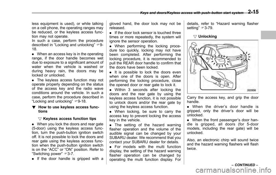
! Unlocking
Carry the access key, and grip the door
handle.
. When the driver ’s door handle is
gripped, only the driver ’s door will be
unlocked.
. When the front passenger ’s door han-
dle is gripped, all doors (for 5-door
models, including the rear gate) will be
unlocked.
Also, an electronic chirp will sound twice
and the hazard warning flashers will flash
twice.
Keys and doors/Keyless access with push –button start system
–CONTINUED –2-15
Page 119 of 594

Keys and doors/Keyless access with push–button start system
dealer.
NOTE
The setting can be changed by your
SUBARU dealer. Contact your SUBARU
dealer for details. Also, for models with
the multi function display, the setting
can be changed by operating the multi
function display. For details, refer to
“Keyless access setting (models with
“keyless access with push-button start
system ”)”F3-84.
& Selecting audible signal op-
eration
Using an electronic chirp, the system will
give you an audible signal when the doors
lock and unlock. If desired, you may turn
the audible signal off. For more details,
contact a SUBARU dealer.
NOTE
For models with the multi function
display, the setting can be changed by
operating the multi function display.
For details, refer to “Keyless buzzer
volume setting ”F 3-79.
& Warning chimes and warning
indicator
The keyless access with push-button start
system sounds a warning chime and
flashes the access key warning indicator
on the combination meter in order to
minimize improper operations and help
protect your vehicle from theft.
For details, refer to “Warning chimes and
warning indicator of the keyless access
with push-button start system ”F 3-25.
& Disabling keyless access
function
WARNING
If you wear an implanted pacemaker
or an implanted defibrillator, per-
form the procedure described in
“By operating the driver ’s door ”
F 2-19 to disable the keyless access
function. If you perform the proce-
dure described in “By operating the
access key ”F 2-18, the operation of
an implanted pacemaker or im-
planted defibrillator may be affected
by the radio waves from the trans-
mitter antenna.
When the vehicle is not going to be used
for a long time, or when you choose not to use the keyless access function, the
keyless access function can be disabled.
NOTE
.
The locking and unlocking function
by the remote keyless entry system is
not disabled.
. The setting can also be changed at
SUBARU dealers. For more details,
contact a SUBARU dealer.
. To start the engine while the func-
tions are disabled, perform the proce-
dure described in “Starting engine”
F 9-19.
. We recommend that you disable the
keyless access functions under the
following conditions.
–When the vehicle is not going to
be used for an extended period of
time
– When the keyless access func-
tions are not going to be used
! Disabling functions
! By operating the access key
If you have registered a PIN code for PIN
Code Access, you can disable the keyless
access function by operating the access
key. For details about registering a PIN
code, refer to “Registering a PIN code”
F 2-22.
1. Open the driver ’s door.
2-18
Page 127 of 594

Keys and doors/Remote keyless entry system
&Selecting audible signal op-
eration (models without
“keyless access with push-
button start system ”)
Using an electronic chirp, the system will
give you an audible signal when the doors
lock and unlock. If desired, you may turn
the audible signal off.
Perform the following steps to deactivate
the audible signal. You can also use the
same steps to restore the function.
1. Sit in the driver ’s seat and shut all
doors and the rear gate.
2. Hold down the REAR (UNLOCK) side
of the power door locking switch.
3. While holding down the REAR (UN-
LOCK) side of the power door locking
switch, pull the key out and re-insert it into the ignition switch at least 6 times within
10 seconds after Step 2.
4. Open and close the driver
’s door once
within 10 seconds after Step 3.
5. The hazard warning flashers flash 3
times to indicate completion of the setting.
You may have the above settings done by
your SUBARU dealer. Also, for models
with a multi function display, the setting
can be changed using the display. For
details, refer to “Keyless buzzer volume
setting ”F 3-79.
& Replacing the battery
Refer to “Replacing key battery ”F 11-43.
& Replacing lost transmitters
If you lose a transmitter or want to
purchase additional transmitters (up to
four can be programmed), your transmit-
ters should be reprogrammed for security
reasons. For details, contact your
SUBARU dealer and have the transmitters
programmed into the remote keyless entry
system.
&Certification for remote key-
less entry system
! U.S.-spec. models
FCC ID: CWTWB1U811
FCC ID: CWTWD1U781
CAUTION
FCC WARNING
Changes or modifications not ex-
pressly approved by the party re-
sponsible for compliance could void
the user ’s authority to operate the
equipment.
NOTE
This device complies with part 15 of the
FCC Rules. Operation is subject to the
following two conditions: (1) This de-
vice may not cause harmful interfer-
ence, and (2) this device must accept
any interference received, including
interference that may cause undesired
operation.
2-26
Page 146 of 594

Ignition switch (models without“keyless
access with push-button start system ”)......... 3-4
LOCK .................................................................. 3-4
ACC.................................................................... 3-5
ON...................................................................... 3-5
START ................................................................ 3-5
Key reminder chime ............................................ 3-5
Ignition switch light (if equipped) ......................... 3-6
Push-button ignition switch (models with
push-button start system) ............................... 3-6
Safety precautions.............................................. 3-6
Operating range for push-button start system ...... 3-6
Switching power ................................................. 3-7
When access key does not operate properly ........ 3-8
Hazard warning flasher....................................... 3-8
Meters and gauges. ............................................. 3-9
Combination meter illumination ........................... 3-9
Canceling the function for meter/gauge needle movement upon turning on the ignition
switch ............................................................... 3-9
Speedometer ...................................................... 3-10
Odometer ........................................................... 3-10
Double trip meter ............................................... 3-11
Tachometer ........................................................ 3-11
Fuel gauge ......................................................... 3-12
ECO gauge (if equipped) .................................... 3-12
Warning and indicator lights ............................. 3-13Initial illumination for system check .................... 3-13
Seatbelt warning light and chime ........................ 3-14
SRS airbag system warning light ........................ 3-15Front passenger
’s frontal airbag ON and OFF
indicators ........................................................ 3-16
CHECK ENGINE warning light/Malfunction indicator light .................................................. 3-16
Coolant temperature low indicator light/Coolant temperature high warning light ......................... 3-17
Charge warning light .......................................... 3-18
Oil pressure warning light .................................. 3-18
Engine low oil level warning light ....................... 3-18
Windshield washer fluid warning light ................ 3-19
AT OIL TEMP warning light (CVT models) ........... 3-19
Low tire pressure warning light (U.S.-spec. models) ........................................................... 3-19
ABS warning light .............................................. 3-21
Brake system warning light (red) ........................ 3-21
Low fuel warning light ....................................... 3-22
Hill start assist warning light/Hill start assist OFF indicator light .................................................. 3-22
Door open warning light .................................... 3-23
All-Wheel Drive warning light (CVT models) ... ..... 3-23
Power steering warning light .............................. 3-23
Vehicle Dynamics Control warning light/Vehicle Dynamics Control operation indicator light .. ..... 3-24
Vehicle Dynamics Control OFF indicator light ..... 3-25
Warning chimes and warning indicator of the keyless access with push-button start system (if
equipped) ........................................................ 3-25
Security indicator light ....................................... 3-30
Select lever/gear position indicator (CVT models) ........................................................... 3-30
Turn signal indicator lights ................................. 3-31
High beam indicator light ................................... 3-31
Instruments and controls
3
Page 147 of 594

Instruments and controls
Cruise control indicator light (if equipped).......... 3-31
Cruise control set indicator light (if equipped) ......................................................... 3-31
Automatic headlight beam leveler warning light (models with HID headlights) ............................ 3-31
Front fog light indicator light (if equipped) .......... 3-31
Headlight indicator light (if equipped) ................. 3-32
Steering responsive fog lights warning indicator/ Steering responsive fog lights OFF indicator
(models with EyeSight system) ......................... 3-32
BSD/RCTA warning indicator (if equipped) .......... 3-32
BSD/RCTA OFF indicator (if equipped) ................ 3-32
Information display (if equipped)...................... 3-32Outside temperature indicator............................ 3-33
Driving information display ................................. 3-33
Clock ................................................................. 3-37
Multi information display (models with type
B combination meter) ..................................... 3-38
Basic operation.................................................. 3-39
Welcome screen and Good-bye screen ............... 3-39
Warning screen .................................................. 3-40
Basic screens .................................................... 3-40
Menu screens .................................................... 3-40
Multi function display ........................................ 3-42Models without multi function display ................. 3-42
Safety precautions ............................................. 3-43
Features ............................................................ 3-43
Locations ........................................................... 3-43
Basic operation .................................................. 3-44
Welcome screen ................................................. 3-44
Date screen ........................................................ 3-44 Ending screen
................................................... 3-45
Self-check screen .............................................. 3-45
Interruption screen ............................................ 3-46
Basic screens .................................................... 3-47
Selection screen ................................................ 3-54
Date and time settings ....................................... 3-57
Image quality and volume settings ..................... 3-64
Screen settings. ................................................. 3-66
Maintenance settings ......................................... 3-74
Driving history registration ................................. 3-77
Car settings ....................................................... 3-78
Initialize ............................................................. 3-86
Light control switch ........................................... 3-89Precautions and tips .......................................... 3-89
Headlights ......................................................... 3-89
High/low beam change (dimmer) ... ..................... 3-91
Headlight flasher ............................................... 3-91
Daytime running light system ............................. 3-92
Turn signal lever................................................ 3-92One-touch lane changer ..................................... 3-93
Illumination brightness control ......................... 3-93
Headlight beam leveler (if equipped) ............... 3-94
Automatic headlight beam leveler (models with
HID headlights) ................................................ 3-94
Fog light switch (if equipped) ........................... 3-94Steering responsive fog lights system (models
with EyeSight system) ..................................... 3-95
Wiper and washer.............................................. 3-96Windshield wiper and washer switches .............. 3-97
Rear window wiper and washer switch –
5-door ............................................................. 3-99
Page 154 of 594

your vehicle under emergency conditions.
The hazard warning flasher works regard-
less of the position of the ignition switch.
To turn on the hazard warning flasher,
push the hazard warning button on the
instrument panel. To turn off the flasher,
push the button again.
NOTE
When the hazard warning flasher is on,
the turn signals do not work.
Meters and gauges
NOTE
Some of the meters and gauges on the
combination meter use liquid-crystal
displays. You will find their indications
hard to see if you wear polarized
glasses.
&Combination meter illumina-
tion
When the ignition switch is turned to the
“ON ”position, various parts of the combi-
nation meter will illuminate in the following
sequence.
1. Warning lights, indicator lights, meter
needles, gauge needles and liquid crystal
display illuminate.
2. Meter and gauge indications each
show MAX position.
3. Meter and gauge indications each
show MIN position.
4. Regular illumination (for driving) be-
gins.
& Canceling the function for
meter/gauge needle move-
ment upon turning on the
ignition switch
It is possible to activate or deactivate the
movement of the meter needles and
gauge needles that takes place when the
ignition switch is turned to the “ON ”
position.
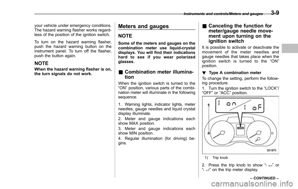
! Type A combination meter
To change the setting, perform the follow-
ing procedure.
1. Turn the ignition switch to the “LOCK”/
“ OFF ”or “ACC ”position.
1) Trip knob
2. Press the trip knob to show “”or
“” on the trip meter display.
Instruments and controls/Meters and gauges
–CONTINUED –3-9