2016 SUBARU IMPREZA turn signal
[x] Cancel search: turn signalPage 306 of 594

!Troubleshooting guide
Experience CauseAction
Mismatch of time alignment - a user may hear
a short period of programming replayed or an
echo, stutter or skip. The radio stations analog and digital volume is
not properly aligned or the station is in ballgame
mode.
None, radio broadcast issue. A user can contact
the radio station.
Sound fades, blending in and out. Radio is shifting between analog and digital
audio. Reception issue. May clear-up as the vehicle
continues to be driven. Turning the indicator of the
HD Radio
TMoff will change the radio mode to
analog audio.
Audio mute condition when an HD2/HD3
multicast channel had been playing. The radio does not have access to digital
signals at the moment. This is normal behavior, wait until the digital signal
returns. If out of the coverage area, seek a new
station.
Audio mute delay when selecting an HD2/
HD3 multicast channel preset. The digital multicast content is not available until
HD Radio
TMbroadcast can be decoded and
make the audio available. This takes up to 7
seconds. This is normal behavior, wait for the audio to
become available.
Text information does not match the present
song audio. Data service issue by the radio broadcaster. Broadcaster should be notified. Complete the form;
www.ibiquity.com/automotive/report_radio
_station_experiences.
No text information shown for the present
selected frequency. Data service issue by the radio broadcaster. Broadcaster should be notified. Complete the form;
www.ibiquity.com/automotive/report_radio
_station_experiences.
The “Acquiring ”caution message appears
when the system attempts to acquire digital
transmission. When acquiring digital data while receiving a
digital broadcast and SPS station. .
When the reception in digital of the SPS station
is confirmed.
. When the system determined that the SPS
station could not be received.
. When the SPS broadcast is ended (stopped) by
the radio station while receiving SPS. Audio/Audio set
–CONTINUED –
5-35
Page 317 of 594

Audio/Audio set
Audio panel
No. Function
&1Turn to adjust volume.
Press to turn the audio system on/off.
&2Press to display the sound setting
screen. Refer to“Unit settings ”F 5-19.
&3Press to display the station operation
screen.
Press to select an audio mode.
&4
Turn to display the next/previous con-
tent item.
Press to select an audio source. Refer
to “Selecting an audio source ”F 5-18.
&5Press to display the next/previous con-
tent item.
NOTE
. For safety reasons, certain func-
tions are not available while your
vehicle is in motion.
. In order to maximize signal recep-
tion, performance and precision of the
smartphone, please ensure the smart-
phone is placed as close to the system
as possible, while ensuring it is stowed
and secure while driving.
. When the ignition switch is in the
“ACC ”or “ON ”position, the battery of
the connected iPhone/iPod touch is
charged.
. iPhone/iPod touch may not be re-
cognized when the ignition switch is in
the “ACC ”or “ON ”position. In this
case, remove the iPhone/iPod touch
and reconnect it.
. The accuracy of the displayed in-
formation or the signal reception per-
formance depends on the smartphone
or the connected device, and it ’s wire-
less connection.
. Since the aha application uses sig-
nals from GPS satellites and wireless
communication lines, it may not work
properly in the following locations.
–In a tunnel
– In underground parking lots
5-46
Page 350 of 594
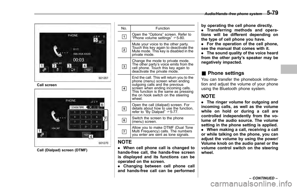
Call screen
Call (Dialpad) screen (DTMF)No. Function
&1Open the
“Options ”screen. Refer to
“ Phone volume settings ”F 5-80.
&2
Mute your voice to the other party.
Touch this key again to deactivate the
Mute mode. This key is disabled in the
private mode.
&3
Change the mode to private mode.
The other party ’s voice emits from the
cell phone. Touch this key again to
deactivate the private mode.
&4
End the call. This will return you to the
phone (menu) screen when ending
outgoing calls and the previous
screen when ending incoming calls.
This function is the same as pressing
the on hook switch on the steering
wheel.
&5Open the call (dialpad) screen. For
details about how to use the function,
refer to “By Dialpad ”F 5-77.
&6Switch the screen to the phone
(menu) screen.
&7Allow you to make DTMF (Dual Tone
Multi Frequency) calls. The numbers
you enter are sent as tone signals.
NOTE
. When cell phone call is changed to
hands-free call, the hands-free screen
is displayed and its functions can be
operated on the screen.
. Changing between cell phone call
and hands-free call can be performed by operating the cell phone directly.
.
Transferring methods and opera-
tions will be different depending on
the type of cell phone you have.
. For the operation of the cell phone,
see the manual that comes with it.
. The sound quality of the voice heard
from the other party’ s speaker may be
negatively impacted.
& Phone settings
You can transfer the phonebook informa-
tion and adjust the volume of your phone
using the Bluetooth phone system.
NOTE
. The ringer volume for outgoing and
incoming calls, as well as the volume
while on hold or during a call are
controlled independently from the vo-
lume of the audio source. The volume
setting in the phone setting is applied.
. When making a call, receiving a call
or while talking on the phone, you can
adjust the volume by using the power/
Volume knob on the audio panel or the
volume control switch on the steering
wheel.
Audio/Hands –free phone system
–CONTINUED –5-79
Page 412 of 594
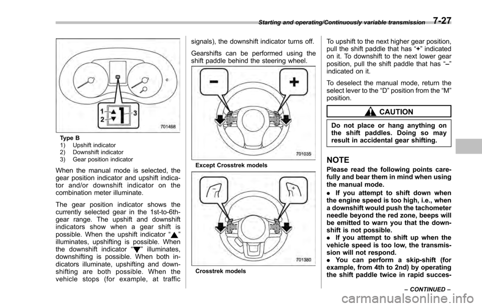
Type B
1) Upshift indicator
2) Downshift indicator
3) Gear position indicator
When the manual mode is selected, the
gear position indicator and upshift indica-
tor and/or downshift indicator on the
combination meter illuminate.
The gear position indicator shows the
currently selected gear in the 1st-to-6th-
gear range. The upshift and downshift
indicators show when a gear shift is
possible. When the upshift indicator“
”
illuminates, upshifting is possible. When
the downshift indicator “
”illuminates,
downshifting is possible. When both in-
dicators illuminate, upshifting and down-
shifting are both possible. When the
vehicle stops (for example, at traffic signals), the downshift indicator turns off.
Gearshifts can be performed using the
shift paddle behind the steering wheel.
Except Crosstrek models
Crosstrek models
To upshift to the next higher gear position,
pull the shift paddle that has
“+”indicated
on it. To downshift to the next lower gear
position, pull the shift paddle that has “–”
indicated on it.
To deselect the manual mode, return the
select lever to the “D”position from the “M”
position.
CAUTION
Do not place or hang anything on
the shift paddles. Doing so may
result in accidental gear shifting.
NOTE
Please read the following points care-
fully and bear them in mind when using
the manual mode.
. If you attempt to shift down when
the engine speed is too high, i.e., when
a downshift would push the tachometer
needle beyond the red zone, beeps will
be emitted to warn you that the down-
shift is not possible.
. If you attempt to shift up when the
vehicle speed is too low, the transmis-
sion will not respond.
. You can perform a skip-shift (for
example, from 4th to 2nd) by operating
the shift paddle twice in rapid succes-
Starting and operating/Continuously variable transmission
–CONTINUED –7-27
Page 424 of 594
pressure threshold, the low tire
pressure warning light should
turn off a few minutes later.
If this light still illuminates while
driving after adjusting the tire
pressure, a tire may have signifi-
cant damage and a fast leak that
causes the tire to lose air rapidly.
If you have a flat tire, replace it
with a spare tire as soon as
possible.
. When a spare tire is mounted or a
wheel rim is replaced without the
original pressure sensor/trans-
mitter being transferred, the low
tire pressure warning light will
illuminate steadily after blinking
for approximately one minute.
This indicates the TPMS is un-
able to monitor all four road
wheels. Contact your SUBARU
dealer as soon as possible for
tire and sensor replacement and/
or system resetting.
. When a tire is repaired with liquid
sealant, the tire pressure warning
valve and transmitter may not
operate properly. If a liquid sea-
lant is used, contact your nearest
SUBARU dealer or other qualified
service shop as soon as possi-
ble. Make sure to replace the tire pressure warning valve and
transmitter when replacing the
tire. You may reuse the wheel if
there is no damage to it and if the
sealant residue is properly
cleaned off. Do not inject any tire
liquid or aerosol tire sealant into
the tires, as this may cause a
malfunction of the tire pressure
sensors. If the light illuminates
steadily after blinking for ap-
proximately one minute,
promptly contact a SUBARU
dealer to have the system in-
spected.
CAUTION
Do not place metal film or any metal
parts in the trunk. This may cause
poor reception of the signals from
the tire pressure sensors, and the
tire pressure monitoring system will
not function properly.
FCC ID: CWTWD1U781
NOTE
This device complies with part 15 of the
FCC Rules. Operation is subject to the
following two conditions: (1) This de-
vice may not cause harmful interfer- ence, and (2) this device must accept
any interference received, including
interference that may cause undesired
operation.
FCC CAUTION
Changes or modifications not ex-
pressly approved by the party respon-
sible for compliance could void the
user
’s authority to operate the equip-
ment.
Starting and operating/Tire pressure monitoring system (TPMS) (U.S. –spec. models)7-39
Page 436 of 594
the BSD/RCTA approach indicator
light may be delayed or it may not
operate at all even when a vehicle is
present in a neighboring lane or
approaching from either side.
The driver is responsible for paying
attention to the rear and side areas
of the vehicle.
&System features
BSD/RCTA consists of the following func-
tions.
. To detect a vehicle in a blind spot on an
adjacent lane or a vehicle approaching at
high speed while driving the vehicle (Blind
Spot Detection)
. To detect a vehicle approaching from
the right or left while reversing the vehicle
(Rear Cross Traffic Alert)
The system uses radar sensors for the
above functions.
NOTE
The BSD/RCTA radar sensor has been
certified by the radio wave related laws
of the U.S. When driving in other
countries, certification of the country
where the vehicle is driven must be
obtained. For certification in the U.S.,
refer to “Certification for the BSD/ RCTA
”F 7-57.
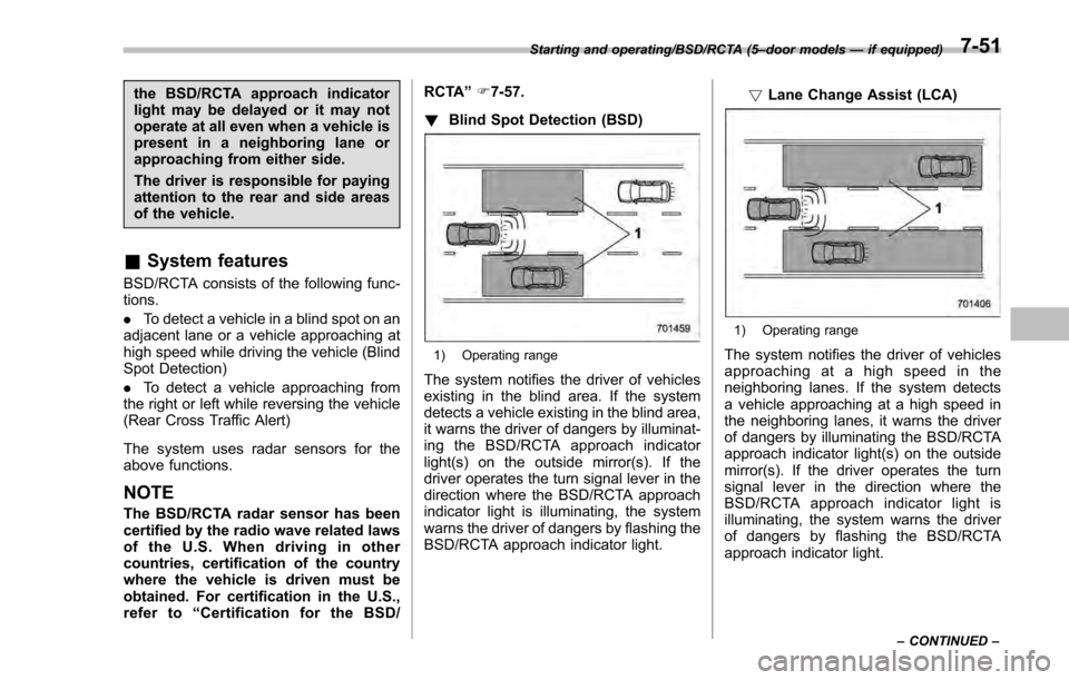
! Blind Spot Detection (BSD)
1) Operating range
The system notifies the driver of vehicles
existing in the blind area. If the system
detects a vehicle existing in the blind area,
it warns the driver of dangers by illuminat-
ing the BSD/RCTA approach indicator
light(s) on the outside mirror(s). If the
driver operates the turn signal lever in the
direction where the BSD/RCTA approach
indicator light is illuminating, the system
warns the driver of dangers by flashing the
BSD/RCTA approach indicator light. !
Lane Change Assist (LCA)
1) Operating range
The system notifies the driver of vehicles
approaching at a high speed in the
neighboring lanes. If the system detects
a vehicle approaching at a high speed in
the neighboring lanes, it warns the driver
of dangers by illuminating the BSD/RCTA
approach indicator light(s) on the outside
mirror(s). If the driver operates the turn
signal lever in the direction where the
BSD/RCTA approach indicator light is
illuminating, the system warns the driver
of dangers by flashing the BSD/RCTA
approach indicator light.
Starting and operating/BSD/RCTA (5 –door models —if equipped)
–CONTINUED –7-51
Page 439 of 594
Starting and operating/BSD/RCTA (5–door models —if equipped)
&BSD/RCTA approach indica-
tor light/warning buzzer
When the BSD/RCTA is active, the BSD/
RCTA approach indicator light will operate
to alert the driver when there are vehicles
in the neighboring lanes. When reversing
the vehicle, the BSD/RCTA approach
indicator light and warning buzzer will
operate to alert the driver that a vehicle
is approaching from the left or right side.
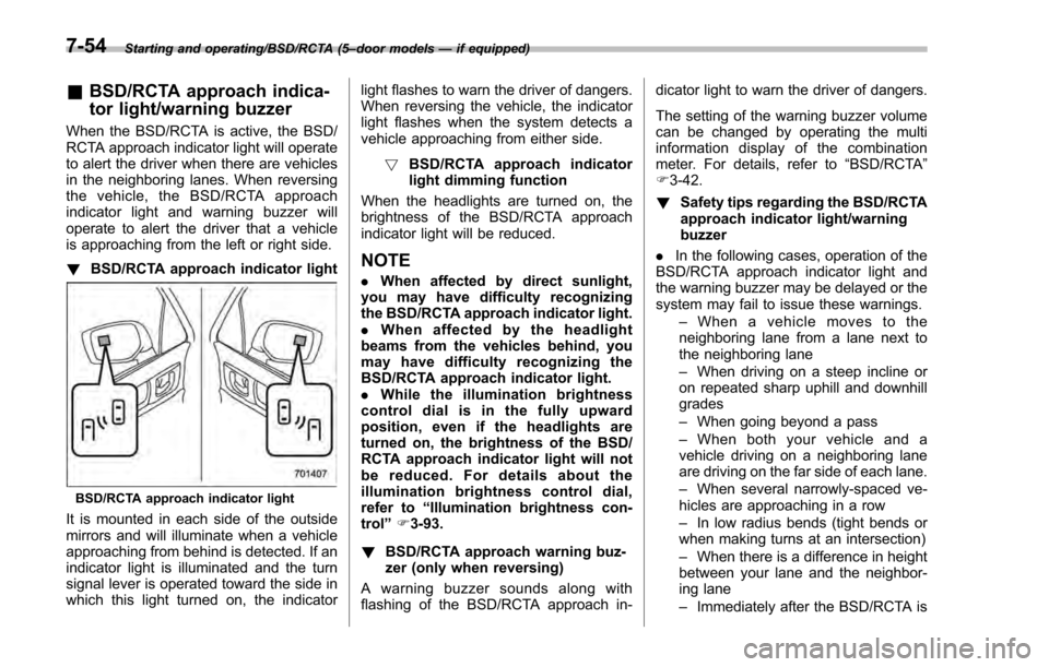
! BSD/RCTA approach indicator light
BSD/RCTA approach indicator light
It is mounted in each side of the outside
mirrors and will illuminate when a vehicle
approaching from behind is detected. If an
indicator light is illuminated and the turn
signal lever is operated toward the side in
which this light turned on, the indicator light flashes to warn the driver of dangers.
When reversing the vehicle, the indicator
light flashes when the system detects a
vehicle approaching from either side.
! BSD/RCTA approach indicator
light dimming function
When the headlights are turned on, the
brightness of the BSD/RCTA approach
indicator light will be reduced.
NOTE
. When affected by direct sunlight,
you may have difficulty recognizing
the BSD/RCTA approach indicator light.
. When affected by the headlight
beams from the vehicles behind, you
may have difficulty recognizing the
BSD/RCTA approach indicator light.
. While the illumination brightness
control dial is in the fully upward
position, even if the headlights are
turned on, the brightness of the BSD/
RCTA approach indicator light will not
be reduced. For details about the
illumination brightness control dial,
refer to “Illumination brightness con-
trol” F3-93.
! BSD/RCTA approach warning buz-
zer (only when reversing)
A warning buzzer sounds along with
flashing of the BSD/RCTA approach in- dicator light to warn the driver of dangers.
The setting of the warning buzzer volume
can be changed by operating the multi
information display of the combination
meter. For details, refer to
“BSD/RCTA”
F 3-42.
! Safety tips regarding the BSD/RCTA
approach indicator light/warning
buzzer
. In the following cases, operation of the
BSD/RCTA approach indicator light and
the warning buzzer may be delayed or the
system may fail to issue these warnings.
–When a vehicle moves to the
neighboring lane from a lane next to
the neighboring lane
– When driving on a steep incline or
on repeated sharp uphill and downhill
grades
– When going beyond a pass
– When both your vehicle and a
vehicle driving on a neighboring lane
are driving on the far side of each lane.
– When several narrowly-spaced ve-
hicles are approaching in a row
– In low radius bends (tight bends or
when making turns at an intersection)
– When there is a difference in height
between your lane and the neighbor-
ing lane
– Immediately after the BSD/RCTA is
7-54
Page 461 of 594
Driving tips/Trailer towing (Crosstrek models)
maximum gross weight. The chains
should cross under the trailer tongue to
prevent the tongue from dropping onto the
ground in case it should disconnect from
the hitch ball. Allow sufficient slack in the
chains taking tight turn situations into
account; however, be careful not to let
them drag on the ground.
WARNING
Do not connect safety chains to any
part of the vehicle other than the
safety chain hooks.
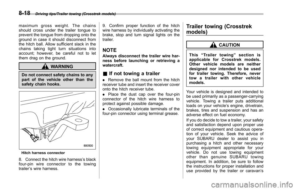
Hitch harness connector
8. Connect the hitch wire harness’s black
four-pin wire connector to the towing
trailer ’s wire harness. 9. Confirm proper function of the hitch
wire harness by individually activating the
brake, stop and turn signal lights on the
trailer.
NOTE
Always disconnect the trailer wire har-
ness before launching or retrieving a
watercraft.
&
If not towing a trailer
. Remove the ball mount from the hitch
receiver tube and insert the receiver cover
onto the hitch receiver tube.
. Place the dust cap over the four-pin
connector of the hitch wire harness to
protect against possible damage.
. Occasionally lubricate terminals of the
four-pin connector using terminal grease.
Trailer towing (Crosstrek
models)
CAUTION
This “Trailer towing ”section is
applicable for Crosstrek models.
Other vehicle models are neither
designed nor intended to be used
for trailer towing. Therefore, never
tow a trailer with other vehicle
models.
Your vehicle is designed and intended to
be used primarily as a passenger-carrying
vehicle. Towing a trailer puts additional
loads on your vehicle’ s engine, drivetrain,
brakes, tires and suspension and has an
adverse effect on fuel economy.
If you do decide to tow a trailer, your safety
and satisfaction depend upon proper use
of correct equipment and cautious opera-
tion of your vehicle. Seek the advice of
your SUBARU dealer to assist you in
purchasing a hitch and other necessary
towing equipment appropriate for your
vehicle. Do not use towing equipment
other than genuine SUBARU towing
equipment. In addition, be sure to follow
the instructions for proper installation and
use provided by the trailer or caravan ’s
8-18