2016 SUBARU IMPREZA ECU
[x] Cancel search: ECUPage 375 of 594
Interior equipment/Ashtray (dealer option)
phone, that may damage the
portion of the socket’s internal
mechanism that causes a cigar-
ette lighter plug to “pop out ”
after its lighter element is heated.
Therefore, do not place a cigar-
ette lighter plug in a socket that
has been used, even once, to
power a plug-in accessory. Doing
so may cause the plug to stick
and overheat, creating a potential
fire hazard.Ashtray (dealer option)
CAUTION
. Do not use ashtrays as waste
receptacles or leave a lighted
cigarette in an ashtray. This
could cause a fire.
. Always extinguish matches and
cigarettes before putting them
into the ashtray, and then close
the ashtray securely. If you keep
the ashtray open, the fire of the
cigarette may spread to another
cigarette butt and start a fire.
. Do not put flammable material in
the ashtray.
. Do not leave a lot of cigarette
butts in the ashtray.
NOTE
Particles of ash and tobacco will accu-
mulate around the hinges of the ash-
tray ’s inner lid. Clean them off using a
toothbrush or a similar narrow-ended
implement.
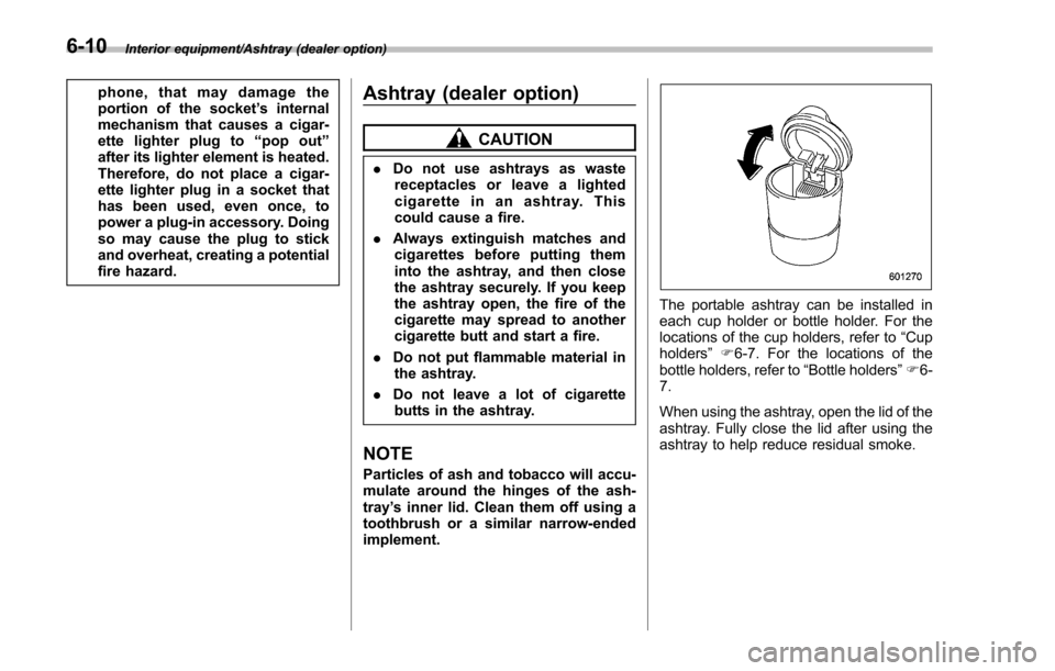
The portable ashtray can be installed in
each cup holder or bottle holder. For the
locations of the cup holders, refer to “Cup
holders ”F 6-7. For the locations of the
bottle holders, refer to “Bottle holders”F 6-
7.
When using the ashtray, open the lid of the
ashtray. Fully close the lid after using the
ashtray to help reduce residual smoke.
6-10
Page 376 of 594
Floor mat (if equipped)
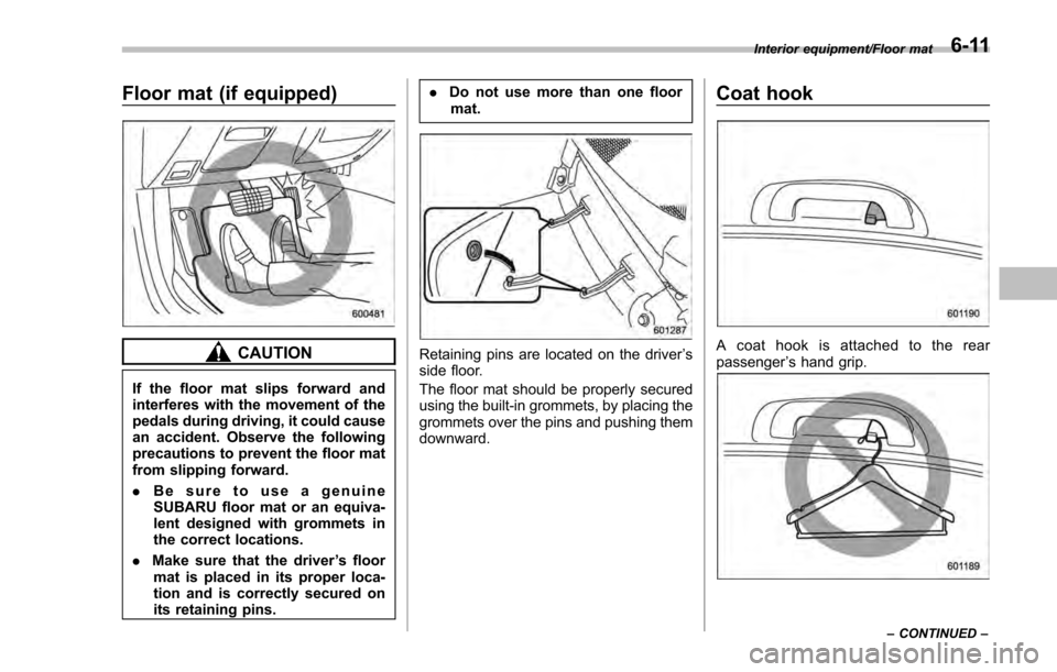
CAUTION
If the floor mat slips forward and
interferes with the movement of the
pedals during driving, it could cause
an accident. Observe the following
precautions to prevent the floor mat
from slipping forward.
.Be sure to use a genuine
SUBARU floor mat or an equiva-
lent designed with grommets in
the correct locations.
. Make sure that the driver ’s floor
mat is placed in its proper loca-
tion and is correctly secured on
its retaining pins. .
Do not use more than one floor
mat.
Retaining pins are located on the driver ’s
side floor.
The floor mat should be properly secured
using the built-in grommets, by placing the
grommets over the pins and pushing them
downward.
Coat hook
A coat hook is attached to the rear
passenger ’s hand grip.
Interior equipment/Floor mat
–CONTINUED –6-11
Page 379 of 594
Interior equipment/Cargo tie–down hooks (5 –door –if equipped)
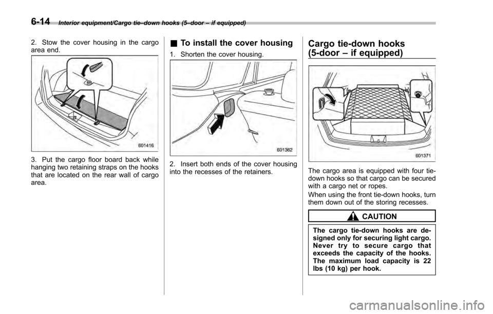
2. Stow the cover housing in the cargo
area end.
3. Put the cargo floor board back while
hanging two retaining straps on the hooks
that are located on the rear wall of cargo
area.
& To install the cover housing
1. Shorten the cover housing.
2. Insert both ends of the cover housing
into the recesses of the retainers.
Cargo tie-down hooks
(5-door –if equipped)
The cargo area is equipped with four tie-
down hooks so that cargo can be secured
with a cargo net or ropes.
When using the front tie-down hooks, turn
them down out of the storing recesses.
CAUTION
The cargo tie-down hooks are de-
signed only for securing light cargo.
Never try to secure cargo that
exceeds the capacity of the hooks.
The maximum load capacity is 22
lbs (10 kg) per hook.
6-14
Page 391 of 594
Starting and operating/Fuel
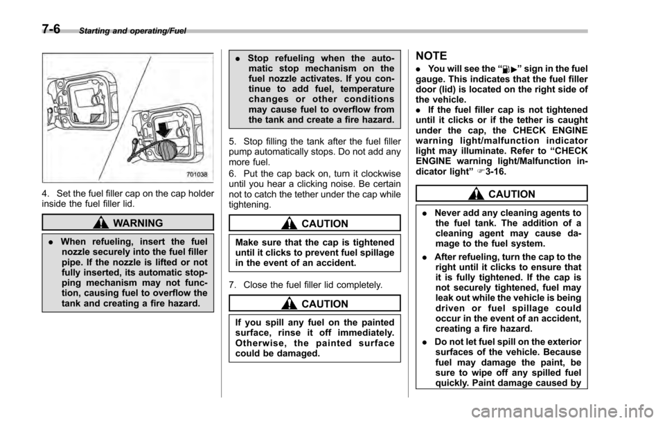
4. Set the fuel filler cap on the cap holder
inside the fuel filler lid.
WARNING
.When refueling, insert the fuel
nozzle securely into the fuel filler
pipe. If the nozzle is lifted or not
fully inserted, its automatic stop-
ping mechanism may not func-
tion, causing fuel to overflow the
tank and creating a fire hazard. .
Stop refueling when the auto-
matic stop mechanism on the
fuel nozzle activates. If you con-
tinue to add fuel, temperature
changes or other conditions
may cause fuel to overflow from
the tank and create a fire hazard.
5. Stop filling the tank after the fuel filler
pump automatically stops. Do not add any
more fuel.
6. Put the cap back on, turn it clockwise
until you hear a clicking noise. Be certain
not to catch the tether under the cap while
tightening.
CAUTION
Make sure that the cap is tightened
until it clicks to prevent fuel spillage
in the event of an accident.
7. Close the fuel filler lid completely.
CAUTION
If you spill any fuel on the painted
surface, rinse it off immediately.
Otherwise, the painted surface
could be damaged.
NOTE
. You will see the “”sign in the fuel
gauge. This indicates that the fuel filler
door (lid) is located on the right side of
the vehicle.
. If the fuel filler cap is not tightened
until it clicks or if the tether is caught
under the cap, the CHECK ENGINE
warning light/malfunction indicator
light may illuminate. Refer to “CHECK
ENGINE warning light/Malfunction in-
dicator light ”F 3-16.
CAUTION
. Never add any cleaning agents to
the fuel tank. The addition of a
cleaning agent may cause da-
mage to the fuel system.
. After refueling, turn the cap to the
right until it clicks to ensure that
it is fully tightened. If the cap is
not securely tightened, fuel may
leak out while the vehicle is being
driven or fuel spillage could
occur in the event of an accident,
creating a fire hazard.
. Do not let fuel spill on the exterior
surfaces of the vehicle. Because
fuel may damage the paint, be
sure to wipe off any spilled fuel
quickly. Paint damage caused by
7-6
Page 397 of 594
Starting and operating/Starting and stopping engine (models with push–button start system)
Starting and stopping engine
(models with push-button
start system)
& Safety precautions
Refer to “Safety precautions ”F 2-10.
& Operating range for push-
button start system
Refer to “Operating range for push-button
start system ”F 3-6.
& Starting engine
WARNING
. There are some general precau-
tions when starting the engine.
Carefully read the precautions
described in “Starting engine ”
F 7-9.
. If the indicator on the push-
button ignition switch flashes in
green after the engine has
started, never drive the vehicle.
The steering is still locked, and it
may result in an accident.
CAUTION
. When the operation indicator on
the push-button ignition switch is
flashing in orange, there may be
a malfunction with the vehicle.
Contact a SUBARU dealer imme-
diately.
. If the indicator on the push-
button ignition switch is flashing
in green after the engine has
started, it means that the steering
is still locked. Depress the brake
pedal while moving the steering
wheel to the right and left, and
press the push-button ignition
switch.
. Do not continue pushing the
push-button ignition switch for
more than 10 seconds. Doing so
could cause a malfunction. If the
engine does not start, stop push-
ing the push-button ignition
switch and turn off the engine.
Wait 10 seconds, and then push
the push-button ignition switch
to start the engine.
NOTE
. When the push-button ignition
switch is pressed while depressing the brake pedal, the engine starter
operates for a maximum of 10 seconds
and after starting the engine, the starter
stops automatically.
.
When the push-button ignition
switch is pressed while depressing
the brake pedal, the engine can be
started regardless of the status of the
push-button ignition switch.
. If the security indicator light illumi-
nates when you attempt to start the
engine but the engine does not start,
press the push-button ignition switch
to switch the power to “OFF”and then
try to start the engine again.
. If the engine does not start, press
the push-button ignition switch without
depressing the brake pedal to switch
the power to “OFF”. Then, while de-
pressing the brake pedal more force-
fully, press the push-button ignition
switch.
. The engine start procedures may
not function depending on the radio
wave conditions around the vehicle. In
such a case, refer to “Starting engine”
F 9-19.
. If the vehicle battery is discharged,
the steering cannot be unlocked.
Charge the battery.
7-12
Page 401 of 594
Starting and operating/Remote engine start system (dealer option)
&Models without “keyless ac-
cess with push-button start
system ”
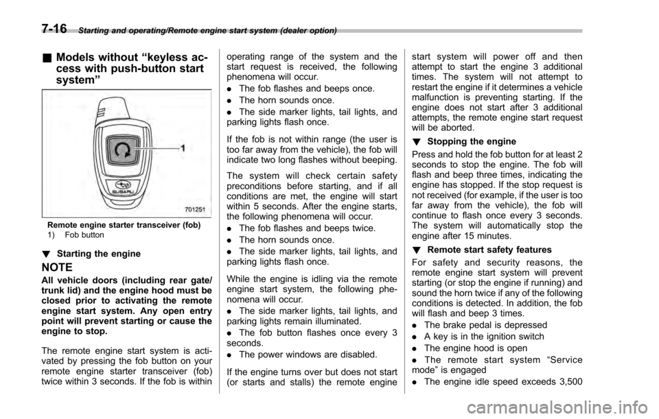
Remote engine starter transceiver (fob)
1) Fob button
!Starting the engine
NOTE
All vehicle doors (including rear gate/
trunk lid) and the engine hood must be
closed prior to activating the remote
engine start system. Any open entry
point will prevent starting or cause the
engine to stop.
The remote engine start system is acti-
vated by pressing the fob button on your
remote engine starter transceiver (fob)
twice within 3 seconds. If the fob is within operating range of the system and the
start request is received, the following
phenomena will occur.
.
The fob flashes and beeps once.
. The horn sounds once.
. The side marker lights, tail lights, and
parking lights flash once.
If the fob is not within range (the user is
too far away from the vehicle), the fob will
indicate two long flashes without beeping.
The system will check certain safety
preconditions before starting, and if all
conditions are met, the engine will start
within 5 seconds. After the engine starts,
the following phenomena will occur.
. The fob flashes and beeps twice.
. The horn sounds once.
. The side marker lights, tail lights, and
parking lights flash once.
While the engine is idling via the remote
engine start system, the following phe-
nomena will occur.
. The side marker lights, tail lights, and
parking lights remain illuminated.
. The fob button flashes once every 3
seconds.
. The power windows are disabled.
If the engine turns over but does not start
(or starts and stalls) the remote engine start system will power off and then
attempt to start the engine 3 additional
times. The system will not attempt to
restart the engine if it determines a vehicle
malfunction is preventing starting. If the
engine does not start after 3 additional
attempts, the remote engine start request
will be aborted.
!
Stopping the engine
Press and hold the fob button for at least 2
seconds to stop the engine. The fob will
flash and beep three times, indicating the
engine has stopped. If the stop request is
not received (for example, if the user is too
far away from the vehicle), the fob will
continue to flash once every 3 seconds.
The system will automatically stop the
engine after 15 minutes.
! Remote start safety features
For safety and security reasons, the
remote engine start system will prevent
starting (or stop the engine if running) and
sound the horn twice if any of the following
conditions is detected. In addition, the fob
will flash and beep 3 times.
. The brake pedal is depressed
. A key is in the ignition switch
. The engine hood is open
. The remote start system “Service
mode ”is engaged
. The engine idle speed exceeds 3,500
7-16
Page 402 of 594
RPM
.The security alarm is triggered
. The select lever is not in the “P ”
position (CVT models)
If the system detects any door (including
the rear gate/trunk lid) open during opera-
tion, it will prevent starting or stop the
engine, and sound the horn and flash side
marker lights, tail lights, and parking lights
6 times.
In addition to the items above, if the
vehicle ’s engine management system
determines there is a safety risk due to a
vehicle-related problem, the vehicle will
power down and the horn will sound 3
times.
NOTE
. If the alarm system is armed at the
time of remote engine starter activation
(the security indicator light on the
combination meter is flashing), the
alarm system will remain armed
throughout the remote start run cycle.
. If the alarm system is disarmed at
the time of remote engine starter
activation (the security indicator light
on the combination meter is not flash-
ing), the alarm system will remain
disarmed throughout the remote start
run cycle. !
Remote start operation - fob con-
firmation
Your remote engine starter fob is a
bidirectional transceiver that can confirm
system operation with several different
visual and audible indications. The fob ’s
LED-backlit button and internal piezo
buzzer will indicate status of the system
using the following flash and beep se-
quences, provided the fob is within opera-
tional range of the system.
Starting and operating/Remote engine start system (dealer option)
–CONTINUED –7-17
Page 409 of 594
Starting and operating/Continuously variable transmission
mission.
. When parking the vehicle, first
securely apply the parking brake
and then place the select lever in
the “P”position. Do not park for
a long time with the select lever
in any other position as doing so
could result in a dead battery.
& Continuously variable trans-
mission features
The continuously variable transmission is
electronically controlled and provides an
infinite number of forward speeds and 1
reverse speed. For some models, it also
has a manual mode or an “L”position.
NOTE
. When the engine coolant tempera-
ture is still low, the transmission will
upshift or downshift at higher engine
speeds than when the coolant tempera-
ture is sufficiently high in order to
shorten the warm-up time and improve
driveability. The gearshift timing will
automatically shift to the normal timing
after the engine has warmed up.
. Immediately after transmission fluid
is replaced, you may feel that the
transmission operation is somewhat
unusual. This results from invalidation of data which the on-board computer
has collected and stored in memory to
allow the transmission to shift at the
most appropriate times for the current
condition of your vehicle. Optimized
shifting will be restored as the vehicle
continues to be driven for a while.
.
When driving a CVT model under
continuous heavy load conditions such
as when towing a camper or climbing a
long, steep hill, the engine speed or the
vehicle speed may automatically be
reduced. This is not a malfunction. This
phenomenon results from the engine
control function maintaining the cool-
ing performance of the vehicle. The
engine and vehicle speed will return to
a normal speed when the engine is able
to maintain the optimum cooling per-
formance after the heavy load de-
creases. Driving under a heavy load
must be performed with extreme care.
Do not try to pass a vehicle in front
when driving on an uphill slope while
towing. .
The continuously variable transmis-
sion is a chain type system that
provides superior transmission effi-
ciency for maximum fuel economy. At
times, depending on varying driving
conditions, a chain operating sound
may be heard that is characteristic of
this type of system.
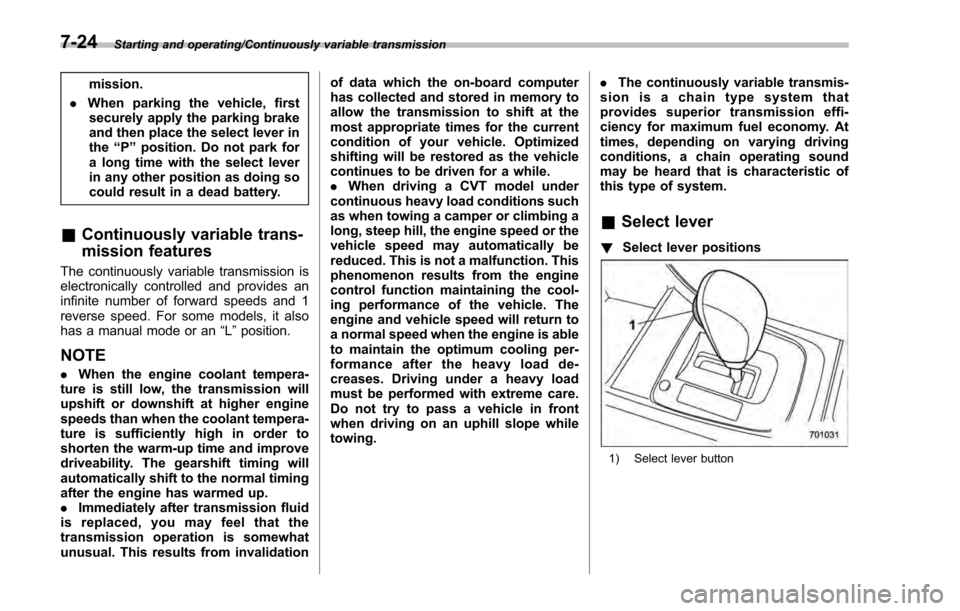
& Select lever
! Select lever positions
1) Select lever button
7-24