2016 SUBARU IMPREZA ECU
[x] Cancel search: ECUPage 135 of 594

Keys and doors/Alarm system
&Tripped sensor identification
The security indicator light flashes when
the alarm system has been triggered.
Also, the number of flashes indicates the
location of unauthorized intrusion or the
severity of impact on the vehicle.
When the ignition switch is turned to the
“ON ”position, the indicator light will light
for 1 second and then flash as follows.
. When a door or the rear gate (5-door)
was opened: 5 times
. When a door or the trunk (4-door) was
opened: 4 times
. When the ignition switch was turned to
the “ON ”position: 3 times
. When a strong impact or multiple
impacts were sensed: twice (only models
with shock sensors (dealer option))
. When a light impact was sensed: once
(only models with shock sensors (dealer
option))
NOTE
Any of the above indicator light flash-
ings will recur each time the ignition
switch is turned to the “ON”position.
Rearming the alarm system cancels the
flashing.
& Shock sensors (dealer op-
tion)
The shock sensors trigger the alarm
system when they sense impacts applied
to the vehicle and when any of their
electric wires are cut. The alarm system
causes the horn to sound and the hazard
warning flashers to flash for a short time
when the sensed impact is weak, but it
warns of a strong impact or multiple
impacts by sounding the horn and flashing
the hazard warning flashers, both lasting
approximately 30 seconds.
If you desire, your SUBARU dealer can
connect them and set them for activation
or deactivation.
NOTE
. The shock sensors are not always
able to sense impacts caused by break-
ing in, and cannot sense an impact that
does not cause vibration (such as
breaking the glass using a rescue
hammer).
. The shock sensors may sense vi-
bration as indicated in the following
examples and trigger the alarm system.
Select the settings of the alarm system
and shock sensors appropriately de-
pending on where you usually park
your vehicle. Examples:
–Vibration from a construction site
– Vibration in a multistory car park
– Vibration from trains
. You can have the sensitivity of the
shock sensors adjusted to your pre-
ference by your SUBARU dealer.
2-34
Page 141 of 594
Keys and doors/Trunk lid (4–door)
time.
WARNING
Never allow any child to get in the
trunk and play with the release
handle. If the driver starts the vehi-
cle without knowing that a child is
inside the trunk and the child opens
the lid using the release handle, the
child could fall out and be killed or
seriously injured.
CAUTION
. Do not close the lid while grip-
ping the release handle. The
handle may be damaged.
. Do not use the handle as a hook
to fasten straps or ropes to
secure your cargo in the trunk.
Such use may result in damage
of the handle. .
Load the trunk so that cargo can
not strike the release handle. If
the cargo hits the handle while
the vehicle is being driven, the
handle may be pulled up and the
trunk lid may open. That may
cause cargo to fall out of the
trunk, which could create a traffic
safety hazard.
! Inspection
Perform the following steps at least twice
a year to check the release handle for
correct operation.
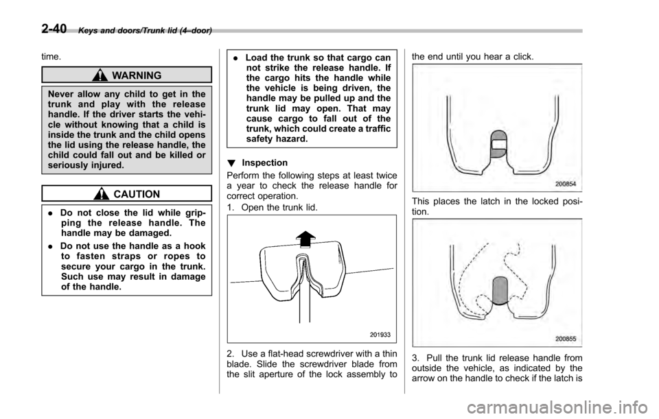
1. Open the trunk lid.
2. Use a flat-head screwdriver with a thin
blade. Slide the screwdriver blade from
the slit aperture of the lock assembly to the end until you hear a click.
This places the latch in the locked posi-
tion.
3. Pull the trunk lid release handle from
outside the vehicle, as indicated by the
arrow on the handle to check if the latch is
2-40
Page 146 of 594

Ignition switch (models without“keyless
access with push-button start system ”)......... 3-4
LOCK .................................................................. 3-4
ACC.................................................................... 3-5
ON...................................................................... 3-5
START ................................................................ 3-5
Key reminder chime ............................................ 3-5
Ignition switch light (if equipped) ......................... 3-6
Push-button ignition switch (models with
push-button start system) ............................... 3-6
Safety precautions.............................................. 3-6
Operating range for push-button start system ...... 3-6
Switching power ................................................. 3-7
When access key does not operate properly ........ 3-8
Hazard warning flasher....................................... 3-8
Meters and gauges. ............................................. 3-9
Combination meter illumination ........................... 3-9
Canceling the function for meter/gauge needle movement upon turning on the ignition
switch ............................................................... 3-9
Speedometer ...................................................... 3-10
Odometer ........................................................... 3-10
Double trip meter ............................................... 3-11
Tachometer ........................................................ 3-11
Fuel gauge ......................................................... 3-12
ECO gauge (if equipped) .................................... 3-12
Warning and indicator lights ............................. 3-13Initial illumination for system check .................... 3-13
Seatbelt warning light and chime ........................ 3-14
SRS airbag system warning light ........................ 3-15Front passenger
’s frontal airbag ON and OFF
indicators ........................................................ 3-16
CHECK ENGINE warning light/Malfunction indicator light .................................................. 3-16
Coolant temperature low indicator light/Coolant temperature high warning light ......................... 3-17
Charge warning light .......................................... 3-18
Oil pressure warning light .................................. 3-18
Engine low oil level warning light ....................... 3-18
Windshield washer fluid warning light ................ 3-19
AT OIL TEMP warning light (CVT models) ........... 3-19
Low tire pressure warning light (U.S.-spec. models) ........................................................... 3-19
ABS warning light .............................................. 3-21
Brake system warning light (red) ........................ 3-21
Low fuel warning light ....................................... 3-22
Hill start assist warning light/Hill start assist OFF indicator light .................................................. 3-22
Door open warning light .................................... 3-23
All-Wheel Drive warning light (CVT models) ... ..... 3-23
Power steering warning light .............................. 3-23
Vehicle Dynamics Control warning light/Vehicle Dynamics Control operation indicator light .. ..... 3-24
Vehicle Dynamics Control OFF indicator light ..... 3-25
Warning chimes and warning indicator of the keyless access with push-button start system (if
equipped) ........................................................ 3-25
Security indicator light ....................................... 3-30
Select lever/gear position indicator (CVT models) ........................................................... 3-30
Turn signal indicator lights ................................. 3-31
High beam indicator light ................................... 3-31
Instruments and controls
3
Page 150 of 594
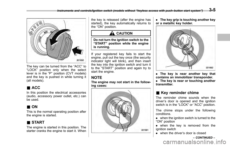
The key can be turned from the“ACC”to
“ LOCK ”position only when the select
lever is in the “P”position (CVT models)
and the key is pushed in while turning it
(all models).
& ACC
In this position the electrical accessories
(audio, accessory power outlet, etc.) can
be used.
&ON
This is the normal operating position after
the engine is started.
&START
The engine is started in this position. The
starter cranks the engine to start it. When the key is released (after the engine has
started), the key automatically returns to
the
“ON ”position.
CAUTION
Do not turn the ignition switch to the
“START ”position while the engine
is running.
If your registered key fails to start the
engine, pull out the key once (the security
indicator light will blink), and then insert
the key into the ignition switch and turn it
to the “START ”position and again try to
start the engine.
NOTE
The engine may not start in the follow-
ing cases:
. The key grip is touching another key
or a metallic key holder.
. The key is near another key that
contains an immobilizer transponder.
. The key is near or touching another
transmitter.
& Key reminder chime
The reminder chime sounds when the
driver ’s door is opened and the ignition
switch is in the “LOCK ”or “ACC ”position.
The chime stops under the following
conditions.
. when the ignition switch is turned to the
“ON ”position
. when the key is removed from the
ignition switch
. when the driver ’s door is closed
Instruments and controls/Ignition switch (models without “keyless access with push –button start system ”)
– CONTINUED –3-5
Page 160 of 594
The warning light(s) for unfastened
seatbelt(s) will alternate between
steady illumination and flashing at
15-second intervals. The chime will
not sound.
–At speeds higher than approxi-
mately 9 mph (15 km/h)
The warning light(s) for unfastened
seatbelt(s) will alternate between
flashing and steady illumination at
15-second intervals and the chime
will sound while the warning light(s)
is/are flashing.
. It is possible to cancel the warning
operation that follows the 6-second
warning after turning ON the ignition
switch. When the ignition switch is
turned ON next time, however, the
complete sequence of the warning
operation resumes. For further details
about canceling the warning operation,
please contact your SUBARU dealer.
If there is no passenger on the front
passenger ’s seat, the seatbelt warning
device for the front passenger ’s seat will
be deactivated. The front passenger ’s
occupant detection system monitors
whether or not there is a passenger on
the front passenger ’s seat.
Observe the following precautions. Failure
to do so may prevent the device from
functioning correctly or cause the device to fail.
.
Do not install any accessory such as a
table or TV onto the seatback.
. Do not store a heavy load in the
seatback pocket.
. Do not allow the rear seat occupant to
place his/her hands or legs on the front
passenger ’s seatback, or allow him/her to
pull the seatback.
. Do not use front seats with their back-
ward-forward position and seatback not
being locked into place securely. If any of
them are not locked securely, adjust them
again. For adjusting procedure, refer to
“Front seats ”F 1-2.
If the seatbelt warning device for the front
passenger ’s seat does not function cor-
rectly (e.g., it is activated even when the
front passenger ’s seat is empty or it is
deactivated even when the front passen-
ger has not fastened his/her seatbelt),
take the following actions.
. Ensure that no article is placed on the
seat other than a child restraint system
and its child occupant, although we
strongly recommend that all children sit
in the rear seat properly restrained.
. Ensure that there is no article left in the
seatback pocket.
. Ensure that the backward-forward po-
sition and seatback of front passenger ’s seat are locked into place securely by
moving the seat back and forth.
If still the seatbelt warning device for front
passenger
’s seat does not function cor-
rectly after taking relevant corrective ac-
tions described above, immediately con-
tact your SUBARU dealer for an inspec-
tion.
&SRS airbag system
warning light
WARNING
If the warning light exhibits any of
the following conditions, there may
be a malfunction in the seatbelt
pretensioners and/or SRS airbag
system. Immediately take your vehi-
cle to your nearest SUBARU dealer
to have the system checked. Unless
checked and properly repaired, the
seatbelt pretensioners and/or SRS
airbag will not operate properly in
the event of a collision, which may
increase the risk of injury.
. Flashing or flickering of the warn-
ing light
. No illumination of the warning
light when the ignition switch is
first turned to the “ON”position
Instruments and controls/Warning and indicator lights
–CONTINUED –3-15
Page 172 of 594

Inside warningchime Outside warning
chime Access key
warning indica-
tor on meter Operation indica-
tor on push-but-
ton ignition switch Status Action
Ding,
ding ...
(intermittent) —— — The driver
’s door was opened while
the push-button ignition switch is
“ ACC ”and the select lever is in the
“ P ”position. Switch the push-button ignition
switch to
“OFF ”, or close the driver ’s
door.
*When exiting the vehicle, be sure to
switch the push-button ignition
switch to “OFF ”.
The push-button ignition switch was
switched to “OFF ”while the driver ’s
door is open. Close the driver
’s door.
Ding Short beep
(2 seconds) —— Lockout warning:
An attempt was made to lock all
doors while the access key is left
inside the vehicle. Take out the access key from the
vehicle, and lock the doors.
*The doors cannot be locked while
the access key is inside the vehicle.
*A chirp sound will be heard, and all
doors will be unlocked.
— Short beep
(2 seconds) —— Trunk lockout warning:
The trunk was closed with the
access key in it while all doors are
locked (or during the automatic lock
time period) (4-door).
Take out the access key from the
trunk, and close the trunk.
*By pressing the trunk opener button
after this warning chime sounds, the
trunk can be unlocked.
Access key lock-in warning:
The door lock sensor was touched
while the push-button ignition switch
is “OFF ”and the access key is
inside the vehicle. Take out the access key from the
vehicle, and lock the doors.
*If the access key is inside the
vehicle, the doors cannot be locked.
— Beep, beep,
beep, beep,
beep
(5 times) —— Door
ajar
warning:
The door lock sensor is touched
while the ignition switch is in the
“ OFF ”position and one of the doors
including the rear gate is opened. Close the doors securely and lock
them.
*If one of the doors including the rear
gate is opened, the doors cannot be
locked.
Instruments and controls/Warning and indicator lights
–CONTINUED –
3-27
Page 175 of 594
Instruments and controls/Warning and indicator lights
&Security indicator light
This indicator light shows the status of the
alarm system. It also indicates operation
of the immobilizer system.
!Alarm system
It blinks to show the driver the operational
status of the alarm system. For detailed
information, refer to “Alarm system ”F 2-
27.
! Immobilizer system
The security indicator light starts blinking
in the following conditions.
For models with “keyless access with
push-button start system ”:
. Immediately after the push-button igni-
tion switch is turned to the “OFF”position.
. Immediately after the driver ’s door is
opened or closed when all of the following
conditions are met.
–The push-button ignition switch is in
the “ON ”or “ACC ”position.
– The access key is outside the
vehicle.
– The engine is not running.
In the event that the push-button ignition
switch is pressed to turn it on or to start
the engine carrying an unauthorized key
(for example, the key is unregistered or
the ID code does not match), the power is not switched to
“ON ”and the security
indicator light continues blinking.
For models without “keyless access
with push-button start system ”:
. Approximately 60 seconds after the
ignition switch is turned from the “ON ”
position to the “ACC”or “LOCK ”position.
. Immediately after the key is pulled out.
If the indicator light does not blink in the
above conditions, it may indicate that
immobilizer system may be malfunction-
ing. Contact your nearest SUBARU dealer
immediately.
In the event that an unauthorized key (for
example, an unauthorized duplicate) is
used to start the engine, the security
indicator light illuminates. For details
about the immobilizer system, refer to
“Immobilizer ”F 2-3.
NOTE
. The security indicator light remains
off in the following conditions. This is
normal and does not indicate a mal-
function.
–while the engine is running
– for approximately 60 seconds
after the ignition switch is turned
from the “ON ”position to the
“ACC ”or “LOCK ”/“OFF ”position
. Even if the security indicator light blinks irregularly or its fuse blows (the
light does not blink if its fuse is blown),
the immobilizer system will function
normally.
&
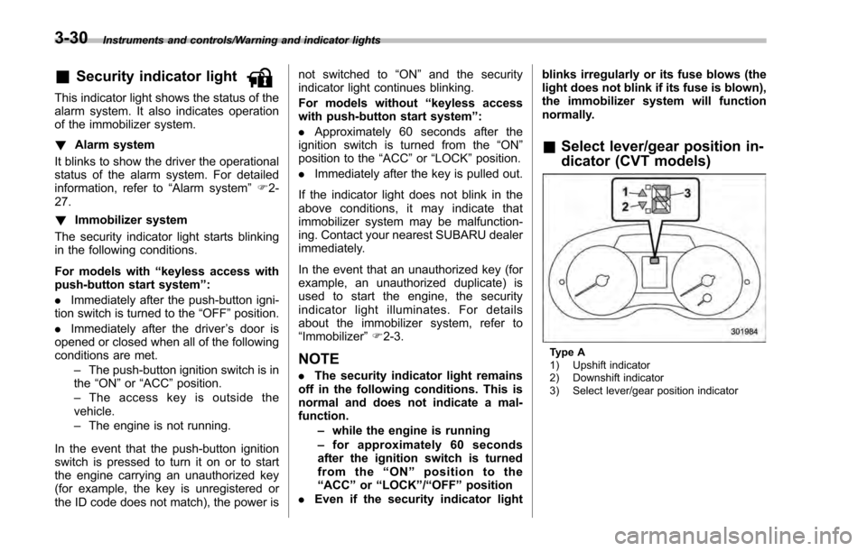
Select lever/gear position in-
dicator (CVT models)
Type A
1) Upshift indicator
2) Downshift indicator
3) Select lever/gear position indicator
3-30
Page 248 of 594
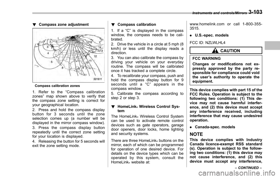
!Compass zone adjustment
Compass calibration zones
1. Refer to the “Compass calibration
zones” map shown above to verify that
the compass zone setting is correct for
your geographical location.
2. Press and hold the compass display
button for 3 seconds until the zone
selection comes up (a number will be
displayed in the mirror compass window).
3. Press the compass display button
repeatedly until the correct zone setting
for your location is displayed.
4. Releasing the button for 5 seconds will
exit the zone setting mode. !
Compass calibration
1. If a “C”is displayed in the compass
window, the compass needs to be cali-
brated.
2. Drive the vehicle in a circle at 5 mph (8
km/h) or less until the display reads a
direction.
3. You can also calibrate the compass by
driving your vehicle on your everyday
routine. The compass will be calibrated
once it has tracked a complete circle.
4. To recalibrate your compass, push and
hold the compass display button for 9
seconds until a “C ” appears in the
compass window.
5. Calibrate the compass according to
step 2 or step 3.
! HomeLink
®Wireless Control Sys-
tem
The HomeLink
®Wireless Control System
can be used to activate remote control
devices such as gate operators, garage
door openers, door locks, home lighting
and security systems.
There are three HomeLink
®buttons on the
mirror, each of which can be programmed
for operation of one desired device. For
details on the device types which can be
operated by this system, consult the
HomeLink
®website at: www.homelink.com or call 1-800-355-
3515.
.
U.S.-spec. models
FCC ID: NZLWLHL4
CAUTION
FCC WARNING
Changes or modifications not ex-
pressly approved by the party re-
sponsible for compliance could void
the user ’s authority to operate the
equipment.
This device complies with part 15 of the
FCC Rules. Operation is subject to the
following two conditions: (1) This de-
vice may not cause harmful interfer-
ence, and (2) this device must accept
any interference received, including
interference that may cause undesired
operation.
. Canada-spec. models
NOTE
This device complies with Industry
Canada licence-exempt RSS standard
(s). Operation is subject to the follow-
ing two conditions: (1) this device may
not cause interference, and (2) this
device must accept any interference,
Instruments and controls/Mirrors
–CONTINUED –3-103