Page 97 of 324

The maximum permissible static load of the individual lashing eyes C and Eis 350 kg.
The maximum permissible load of the individual lashing eyes is D
is 150 kg.
Fixing nets
Fig. 104
Fastening examples for nets
Fig. 105
Fastening vertical pocket
Read and observe and on page 94 first.
Fastening examples for nets » Fig. 104 and » Fig. 105
Horizontal pocket
Floor net
Vertical pocket
The maximum permissible load of each of the nets is 1.5 kg.
If the vehicle is equipped with the variable loading floor and this is in the upper
position, then the lashing eyes
E
» Fig. 103 on page 94 can be used for attach-
ing the nets.
ABCCAUTIONOn vehicles with lashing eyesD » Fig. 102 on page 94 only the cross-bag are
attached behind the seats and the floor net (the net can be attached to the
rear fastenersA
» Fig. 102 on page 94 at the rear).
Multifunction pocket
Fig. 106
Securing the multifunction pock-
et
Read and observe and on page 94 first.
The pocket » Fig. 106 can be secured to the fastening elements
A
and the
rear and centre lashing eyes
C
» Fig. 102 on page 94 .
The maximum permissible load for the bag attached to the fastening element
is 3 kg.
CAUTION
In vehicles with a variable loading floor, it is not possible to attach the bag to
the fastening elements.95Transport of cargo
Page 98 of 324

Folding double hooksFig. 107
Folding double hooks
Read and observe and on page 94 first.
Folding double hooks» Fig. 107 for attaching small items of luggage, such as
bags etc. are provided on one or both sides of the luggage compartment de-
pending on the equipment installed in the vehicle (e.g. Bags etc.).
An item of luggage with a maximum weight of 5 kg can be attached to each
side of the double hook.
Foldable hook
Fig. 108
Fold down hook
Read and observe and on page 94 first.
Foldable hooks for hanging small items of luggage, such as bags, etc., are pro- vided on both sides of the luggage compartment.
›
To the use on the lower part
A
Press the hook and pull it down in direction
of the arrow » Fig. 108.
The maximum permissible load of the hook is 7 kg.
Fasten the flooringFig. 109
Fixing the floor covering: Version 1 / version 2
Read and observe
and on page 94 first.
Fastening options for the flooring » Fig. 109
With the loop on a hook on the luggage compartment cover
With the hook on the frame of the luggage compartment lid
CAUTION
For version 1, the following information applies.■The hook on the luggage compartment cover is only provided for the fixing of
the floor covering, do not hang objects on it - there is a risk of damage to hook.■
The flooring must be secured on the hook only with an open boot, therefore,
before closing the lid, check to see if the flooring is attached to the hook -
there is a risk of damage to hook.
CAUTION
The floor covering can be fixed with Version 2 only if the variable loading floor
is folded in the upper position » Fig. 121 on page 101 .
Floor covering on both sides
Read and observe
and on page 94 first.
You can fit a double-sided floor covering in the luggage compartment. One
side is made of fabric, the other side is washable (suitable for transporting wet
or dirty items ).
96Using the system
Page 99 of 324

CAUTIONThe double sided floor covering can only be used in vehicles without the varia-
ble loading floor » page 100 - There is a risk of damage to the variable loading
floor.
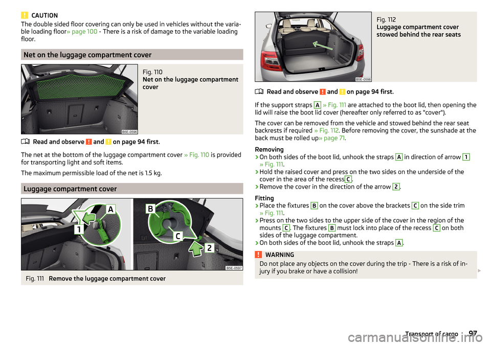
Net on the luggage compartment cover
Fig. 110
Net on the luggage compartment
cover
Read and observe and on page 94 first.
The net at the bottom of the luggage compartment cover » Fig. 110 is provided
for transporting light and soft items.
The maximum permissible load of the net is 1.5 kg.
Luggage compartment cover
Fig. 111
Remove the luggage compartment cover
Fig. 112
Luggage compartment cover
stowed behind the rear seats
Read and observe and on page 94 first.
If the support straps
A
» Fig. 111 are attached to the boot lid, then opening the
lid will raise the boot lid cover (hereafter only referred to as "cover").
The cover can be removed from the vehicle and stowed behind the rear seat
backrests if required » Fig. 112. Before removing the cover, the sunshade at the
back must be rolled up » page 71.
Removing
›
On both sides of the boot lid, unhook the straps
A
in direction of arrow
1
» Fig. 111 .
›
Hold the raised cover and press on the two sides on the underside of the
cover in the area of the recess
C
.
›
Remove the cover in the direction of the arrow
2
.
Fitting
›
Place the fixtures
B
on the cover above the brackets
C
on the side trim
» Fig. 111 .
›
Press on the two sides to the upper side of the cover in the region of the
mounts
C
. The fixtures
B
must lock into place of the recess
C
on both
sides of the luggage compartment.
›
On both sides of the boot lid, unhook the straps
A
.
WARNINGDo not place any objects on the cover during the trip - There is a risk of in-
jury if you brake or have a collision! 97Transport of cargo
Page 100 of 324

CAUTION■Observe the following instructions to avoid canting and the subsequent
damage to the cover or the side trim. ■ The cover must be inserted properly and the load must not exceed the
height of the cover.
■ The cover must not be jammed in the surrounding seal of the luggage com-
partment lid when it is in the raised position. ■ There must be no object in the gap between the cover in the raise position
and the rear backrest.
Roll-up cover
Fig. 113
Roll-up cover: Pull out / roll up / remove
Fig. 114
Removing side covers / stowing foldable luggage compartment
cover
Read and observe and on page 94 first.
Extending
›
Grasp the cover on the handle
A
and pull it out in the direction of the arrow
1
until it clicks » Fig. 113.
Retracting
›
Push the cover in the area of handle
A
in the direction of the arrow
2
» Fig. 113 . The cover rolls up automatically. The rolled-up cover can now be
removed.
Removing/inserting
›
Press on the side of the cross bar in the direction of arrow
3
and remove
the cover in the arrow direction
4
» Fig. 113 .
Insertion takes place in reverse order.
Stowage
If the vehicle is equipped with the variable loading floor, then the removable
roll-up luggage compartment cover can be stowed in the recesses of the lug-
gage compartment side trim.
›
Fold the variable loading floor into the upper position » page 101.
›
Remove the side covers in the direction of arrows
1
» Fig. 114 .
›
Insert the front part of the roll-up luggage compartment cover under a por-
tion of the side trim
D
on the left.
›
Fold the rear part of the roll-up luggage compartment cover in the direction
of the arrow
2
.
›
Reinsert the lamp in the opposite direction to the arrow
1
.
›
Fold out the variable loading floor to the upper position.
WARNINGNo objects should be placed on the roll-up cover - there is a risk of damage
to the cover and a risk of injury in the event of a sudden stop or a vehicle
collision!
Note
If you want to stow the roll-up luggage compartment cover and the roof rack
at the same time , then it is necessary that the rear part of the roll-up luggage
compartment is covering the rear roof rack.98Using the system
Page 101 of 324

Storage compartment with cargo elementFig. 115
Remove storage compartment
Fig. 116
Remove cargo element / Load fastening example
Read and observe
and on page 94 first.
The storage compartment with cargo element may be located on either of the
two sides of the luggage compartment, depending on the equipment variant.
The space behind the storage compartment is designed for storing small ob-
jects with a maximum total weight of 2.5 kg.
The cargo element is designed for attaching and securing objects with a maxi-
mum total weight of 8 kg.
Storage compartment
›
Remove the storage compartment cover in the direction of the ar-
row » Fig. 115 . Insertion takes place in reverse order.
Cargoelement
›
Before use, remove theCargoelement in the direction of arrow » Fig. 116 -
.
›
Use thecargoelements to secure the load as close as possible to the rear
seats » Fig. 116
.
›After use, stow the cargoelements in their original position.
Storage compartments under the floor covering
Fig. 117
Lift floor covering/storage compartments under the floor cover-
ing
Read and observe
and on page 94 first.
For vehicles that are not equipped with an emergency wheel located under theflooring of the luggage compartment
B
» Fig. 117 .
Every storage compartment
B
is designed for storing small objects of up to 15
kg. in weight in total.
Use of the storage compartments
›
Dividing the luggage compartment with variable loading floor » page 102.
›
Lift the floor covering in the direction of arrow » Fig. 117 and hook into hook
A
on the upper edge of the variable loading floor.
›
Stow the cargo in the storage compartments.
›
Unhook hook
A
and fold back the flooring against the direction of the arrow
(fold back the variable loading floor to the initial position if necessary).
When transporting tall objects in the compartments, the hook
A
must be
hooked onto the upper edge of the variable loading floor.
CAUTION
Before closing the boot lid, check that the cargo transported in the storage
compartments does not strike against the luggage compartment cover - there
is a risk of damage to the lid.99Transport of cargo
Page 102 of 324

Multi-function pocketFig. 118
Multi-function pocket: Pull out / insert / push in / remove multi-
function pocket
Read and observe
and on page 94 first.
The multifunction pocket (hereinafter referred to as pocket) is provided for
storing clothing and light objects with no sharp edges.
The maximum permissible load of the multifunction box is 3 kg.
Removal and fitting
›
Fold down the front hooks on both sides of the luggage compartment in the
direction of arrow
1
» Fig. 118 .
›
Grasp the rear bar
A
with both hands and withdraw the pocket in arrow di-
rection
2
.
›
Place the rear bar onto the two hooks that are folded forward in the direc-
tion of the arrow
3
all the way to the stop.
Pushing in
›
Remove the rear bar of the hook in direction of arrow
4
push in the pocket
in the direction of arrow
5
» Fig. 118 .
›Place the rear bar against the front bar and press them together at both
ends B.›
The front hooks on both sides of the luggage compartment fold back oppo-
site to the direction of arrow
1
.
Removing/inserting
›
Remove the roll-up cover » page 98.
›
Remove the pocket from the fittings in the direction of the arrow
6
» Fig. 118.
Insertion takes place in reverse order.
›
Insert the end of the bar marked with
in the right-hand mounting and the
end of the bar marked with
in the left-hand mounting. The arrows should
be pointing forward.
Class N1 vehicles
Read and observe
and on page 94 first.
In class N1 vehicles that are not fitted with a protective grille, a lashing set that
complies with the EN 12195 standard (1-4) must be used for fastening the load.
Proper functioning of the electrical installation is essential for safe vehicle op-
eration. It is important to ensure that the electrical installation is not damaged
during the adjustment process or when the storage area is being loaded and
unloaded.
Variable loading floor in the luggage compartment (Estate)
Introduction
This chapter contains information on the following subjects:
Positions of the variable loading floor
101
Fold together / fold out the variable loading floor
101
Dividing the luggage compartment
102100Using the system
Page 103 of 324

Positions of the variable loading floorFig. 119
Set variable loading floor to the upper position / variable loading
floor in the upper position
Fig. 120
Set variable loading floor to the lower position / variable loading
floor in the lower position
The variable loading floor can be set to the upper or lower position.
Set to the upper position
›
Lift the variable loading floor by the handle
A
» Fig. 119 about 20 cm high and
pull towards you.
›
Lift the loading floor to the height of the roll-up luggage compartment cover
in the direction of arrow
1
until you hear the clicking sound and press for-
ward.
The space below the variable loading floor can be used for stowing objects
such as the removed roll-up luggage compartment cover » page 98, the roof
cross bars » page 103 etc.
The maximum permissible load of the variable loading floor is 75 kg. For the
transport of heavy loads, adjust the variable loading floor in the lower position
» Fig. 120 .
Set into the lower position›
Check that the area below the variable loading floor is empty.
›
Lift the variable loading floor by the handle
A
» Fig. 120 over the loading edge
in the direction of arrow
2
.
›
Pull the loading floor towards you in the direction of arrow
3
until it sinks to
the bottom position, and push forward.
Fold together / fold out the variable loading floor
Fig. 121
Fold up variable loading floor / folded variable cargo floor in the
upper position
›
To fold together , hold the variable loading floor on the handle
A
and lift in
the direction of arrow
1
» Fig. 121 .
›
Fold up the variable loading floor by moving it in the direction of the arrow
2
.
Folding out takes place in reverse order.
The variable loading floor is folded together / out in the same way in the upper
and lower position.
101Transport of cargo
Page 104 of 324

Dividing the luggage compartmentFig. 122
Dividing the boot with variable
loading floor
›
To divide , lift the variable loading floor by the handle
A
and push in the rear
edge of the variable loading floor in the grooves
B
in the direction of the ar-
row » Fig. 122 .
The variable loading floor is secured against movements in the grooves
B
.
Folding out takes place in reverse order.
The variable loading floor is divided in the same way in the upper and lower
position.
Net partition
Introduction
This chapter contains information on the following subjects:
Using the net partition
102
Removing and installing the net partition housing
103Using the net partitionFig. 123
Open part of the roll-up luggage compartment cover / release
lever
Fig. 124
Correctly secure net partition behind the front seats in the
pulled-out state
The net partition can either be pulled out and secured from behind the rear
seats or behind the front seats.
Pull out and secure the net partition behind the rear seats
›
Fold out part
A
of the roll-up luggage compartment cover in the direction of
arrow » Fig. 123 .
›
Pull out the net partition at the crossbar
C
and hook into one of the recep-
tacles
D
» Fig. 124 .
102Using the system