Page 186 of 258
5.2
In case of puncture
Depending on the vehicle, a tyre infla-
tion kit or emergency spare wheel is
provided (refer to the following pages).
Vehicle fitted with a tyre pressure
loss warning system
If under-inflated (puncture, low pres-
sure, etc.), the warning light
�
on the instrument panel comes on.
See “Tyre pressure loss warning” in
Section 2.
If the emergency spare wheel has been stored for several years, have it \
checked by your Dealer to ensure that it is safe to use.
Vehicle fitted with an emergency spare wheel that differs from the
other wheels:
– Never fit more than one emergency spare wheel to the same vehicle.
– As the punctured wheel is wider than the emergency spare wheel, the vehi\
cle’s ground clearance is reduced.
– Replace the emergency spare wheel as soon as possible with a wheel ident\
i- cal to the original one.
– When this is fitted to the vehicle, which must only be a temporary measu\
re, the driving speed must not exceed the speed indicated on the label on the wh\
eel.
– Fitting an emergency spare wheel may alter the way the vehicle usually r\
uns. Avoid sudden acceleration or deceleration and reduce your speed when cor-\
nering.
– If you need to use snow chains, fit the emergency spare wheel to the rea\
r axle and check the tyre pressure.
PUNCTURE, EMERGENCY SPARE WHEEL (1/4)
Page 191 of 258

5.7
TYRE PRESSURE KIT (2/3)
Depending on the vehicle, in the event
of a puncture, use the kit located in the
boot or underneath the luggage com-
partment carpet.
Vehicle fitted with a tyre pressure
loss warning system
If under-inflated (puncture, low pres-
sure, etc.), the warning light
� on
the instrument panel comes on. See
“Tyre pressure loss warning” in
Section 2.
With the engine running and the
parking brake applied,
– unroll the hose from the container;
– connect the compressor hose 3 to
the container’s inlet 8;
– depending on the vehicle, connect the container 8 to the compressor
from the container recess 7;
– unscrew the valve cap on the rele- vant wheel and screw on the con-
tainer’s inflation adapter 1;
– disconnect any accessories previ- ously connected to the vehicle’s ac-
cessories sockets;
– adapter 2 must be connected to the
vehicle accessories socket;
45
1
Before using this kit, park
the vehicle at a sufficient
distance from traffic, switch
on the hazard warning
lights, apply the handbrake, ask all
passengers to leave the vehicle and
keep them away from traffic.
8
If the vehicle is parked on
the hard shoulder, you must
warn other road users of
your vehicle’s presence
with a warning triangle or with other
devices as per the legislation apply-
ing to the country you are in.
– press switch 4 to inflate the tyre to
the recommended pressure (please
refer to the information in the section
on “Tyre pressure”);
– after a maximum of 15 minutes, stop inflating and read the pressure (on
pressure gauge 5).
Note: while the container is empty-
ing (approximately 30 seconds), the
pressure gauge 5 will briefly indicate
a pressure of up to 6 bar. The pres-
sure will then drop.
– adjust the pressure: to increase it, continue inflation with the kit; to
reduce it, press button 6.
2
3
7
6
Page 195 of 258
5.11
Continue to crank the jack so that the
baseplate is correctly positioned (it
should be underneath the vehicle and
aligned with the jack head).
Turn it a few times to lift the wheel off
the ground.
Switch on the hazard warn-
ing lights.
Keep the vehicle away from
traffic and on a level surface
where it will not slip.
Apply the parking brake and engage
a gear (first or reverse, or P for auto-
matic transmissions).
Ask all the passengers to leave the
vehicle and keep them away from
traffic.
CHANGING A WHEEL (1/2)
2
1
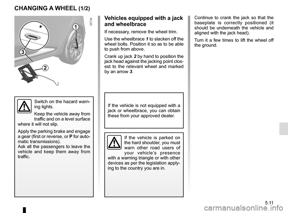
Vehicles equipped with a jack
and wheelbrace
If necessary, remove the wheel trim.
Use the wheelbrace 1 to slacken off the
wheel bolts. Position it so as to be able
to push from above.
Crank up jack 2 by hand to position the
jack head against the jacking point clos-
est to the relevant wheel and marked
by an arrow 3.
If the vehicle is not equipped with a
jack or wheelbrace, you can obtain
these from your approved dealer.
3
If the vehicle is parked on
the hard shoulder, you must
warn other road users of
your vehicle’s presence
with a warning triangle or with other
devices as per the legislation apply-
ing to the country you are in.
Page 196 of 258
5.12
If you have a puncture, re-
place the wheel as soon as
possible.
A tyre which has been punc-
tured should always be inspected
(and repaired, where possible) by a
specialist.
CHANGING A WHEEL (2/2)
Undo the bolts and take off the wheel.
Fit the emergency spare wheel on the
central hub and turn it to locate the
mounting holes in the wheel and the
hub.
Tighten the bolts, checking that the
wheel is correctly positioned on its hub.
Lower the jack.
With the wheel on the ground, tighten
the bolts fully and have the tightness of
the bolts checked and the emergency
spare wheel pressure checked as soon
as possible.
Do not leave the tools un-
secured inside the vehicle
as they may come loose
under braking. After use,
check that all the tools are correctly
clipped into the tool kit, then posi-
tion it correctly in its housing: risk of
injury.
If wheel bolts are supplied in the
tool kit, only use these bolts for the
emergency spare wheel: refer to the
label affixed to the emergency spare
wheel.
The jack is designed for wheel
changing purposes only. Under no
circumstances should it be used for
carrying out repairs underneath the
vehicle or to gain access to the un-
derside of the vehicle.
Vehicle fitted with a tyre pressure
loss warning system
If under-inflated (puncture, low pres-
sure, etc.), the warning light
� on
the instrument panel comes on. See
“Tyre pressure loss warning” in
Section 2.
Page 198 of 258
5.14
Vehicle fitted with a tyre pressure
loss warning system
If under-inflated (puncture, low pres-
sure, etc.), the warning light
� on
the instrument panel comes on. See
“Tyre pressure loss warning” in
Section 2.
Pressures should be checked when the
tyres are cold; ignore higher pressures
which may be reached in hot weather
or following a fast journey.
If tyre pressures cannot be checked
when the tyres are cold, assume an in-
crease of 0.2 to 0.3 bar (or 3 PSI).
Never deflate a hot tyre.
TYRES (2/3)
Please be aware that a
poorly tightened or miss-
ing valve cap can make the
tyres less airtight and lead
to pressure loss.
Always use valve caps identical to
those fitted originally and tighten
them fully.
Incorrect tyre pressures
lead to abnormal tyre wear
and unusually hot running.
These are factors which
may seriously affect safety and lead
to:
– poor road holding,
– risk of bursting or tread separa- tion.
The pressure depends on the load
and the speed of use. Adjust the
pressure according to the condi-
tions of use (refer to the label affixed
to the edge of the driver’s door).
Tyre pressures
Adhere to the tyre pressures (including
the emergency spare wheel). The tyre
pressures should be checked at least
once a month and additionally before
any long journey (refer to the label af-
fixed to the edge of the driver’s door).
Page 200 of 258
5.16
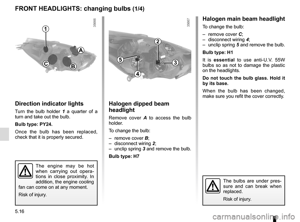
Halogen dipped beam
headlight
Remove cover A to access the bulb
holder.
To change the bulb:
– remove cover B;
– disconnect wiring 2;
– unclip spring 3 and remove the bulb.
Bulb type: H7
FRONT HEADLIGHTS: changing bulbs (1/4)
The engine may be hot
when carrying out opera-
tions in close proximity. In
addition, the engine cooling
fan can come on at any moment.
Risk of injury.
B
Halogen main beam headlight
To change the bulb:
– remove cover C;
– disconnect wiring 4;
– unclip spring 5 and remove the bulb.
Bulb type: H1
It is essential to use anti-U.V. 55W
bulbs so as not to damage the plastic
on the headlights.
Do not touch the bulb glass. Hold it
by its base.
When the bulb has been changed,
make sure you refit the cover correctly.
C
2
4
53
Direction indicator lights
Turn the bulb holder 1 a quarter of a
turn and take out the bulb.
Bulb type: PY24.
Once the bulb has been replaced,
check that it is properly secured.
1
A
The bulbs are under pres-
sure and can break when
replaced.
Risk of injury.
Page 201 of 258
5.17
FRONT HEADLIGHTS: changing bulbs (2/4)
Discharge bulb main beam
headlights/dipped beam
headlights
Never open the cover D.
Bulb type: D5S.
D
Due to the danger involved
in handling high-voltage de-
vices, this type of bulb must
be replaced by an approved
dealer.
A special mounting is re-
quired to fit this type of
headlight, it is forbidden to
fit a headlight with xenon
bulbs to a vehicle which was not
designed for it.
Before performing any
action in the engine com-
partment, the ignition must
be switched off by pressing
the engine stop button (please see
the information on “Starting, stop-
ping the engine” in Section 2).
Any operation on (or modi-
fication to) the electrical
system must be performed
by an approved dealer
since an incorrect connection might
damage the electrical equipment
(harness, components and in partic-
ular the alternator). In addition, your
Dealer has all the parts required for
fitting these units.
Page 202 of 258
5.18
Front side light(depending on the vehicle)
To change a bulb, remove cover A.
Pull bulb holder 6 to access the bulb.
Bulb type: W5W.
The engine may be hot
when carrying out opera-
tions in close proximity. In
addition, the engine cooling
fan can come on at any moment.
Risk of injury.
To comply with local legislation, or
as a precaution, you can obtain an
emergency kit containing a set of
spare bulbs and fuses from an ap-
proved dealer.
A
6
FRONT HEADLIGHTS: changing bulbs (3/4)
7
Daytime running lights 7(depending on the vehicle)
Please see an authorised dealer.
The bulbs are under pres-
sure and can break when
replaced.
Risk of injury.