Page 17 of 380
VQ40DE engine
1. Fuse/Fusible link box (P. 8-24)
2. Engine oil filler cap (P. 8-11)
3. Engine oil dipstick (P. 8-11)
4. Brake fluid reservoir (P. 8-16)
5. Air cleaner (P. 8-21)
6. Windshield-washer fluid reservoir(P. 8-16)
7. Engine coolant reservoir (P. 8-9)
8. Drive belt location (P. 8-19)
9. Power steering fluid reservoir (P. 8-15)
10. Radiator cap (P. 8-9)
11. Battery (P. 8-17)
Refer to the page number indicated in pa-
rentheses for operating details.
LDI2615
ENGINE COMPARTMENT CHECK
LOCATIONS
0-8Illustrated table of contents
Page 18 of 380
VK56DE engine
1. Fuse/Fusible link box (P. 8-24)
2. Power steering fluid reservoir (P. 8-15)
3. Engine coolant reservoir (P. 8-9)
4. Brake fluid reservoir (P. 8-16)
5. Air cleaner (P. 8-21)
6. Windshield-washer fluid reservoir(P. 8-16)
7. Drive belt location (P. 8-19)
8. Engine oil filler cap (P. 8-11)
9. Engine oil dipstick (P. 8-11)
10. Radiator cap (P. 8-9)
11. Battery (P. 8-17)
NOTE:
Engine cover removed for clarity.
Refer to the page number indicated in pa-
rentheses for operating details.
LDI2655
Illustrated table of contents0-9
Page 25 of 380

Operating tips
●The power seat motor has an auto-reset
overload protection circuit. If the motor
stops during operation, wait 30 seco")
FRONT POWER SEAT ADJUSTMENT
(if so equipped for driver’s seat)
Operating tips
●The power seat motor has an auto-reset
overload protection circuit. If the motor
stops during operation, wait 30 seconds
then reactivate the switch.
● Do not operate the power seat switch for a
long period of time when the engine is off.
This will discharge the battery.
Forward and backward
Moving the switch forward or backward will slide
the seat forward or backward to the desired
position.
Reclining
Move the recline switch backward until the de-
sired angle is obtained. To bring the seatback
forward again, move the switch forward and
move your body forward. The seatback will move
forward. The reclining feature allows adjustment of the
seatback for occupants of different sizes for
added comfort and to help obtain proper seat
belt fit. For additional information, refer to “Pre-
cautions on seat belt usage” in this section. Also,
the seatback can be reclined to allow occupants
to rest when the vehicle is stopped and the shift
lever is in P (Park) .
LRS2029
1-4Safety—Seats, seat belts and supplemental restraint system
Page 92 of 380

CAUTION
●This gauge is not designed to indicate
low engine oil level. Use the dipstick to
check the oil level. For additional infor-
mation, refer to “Engine oil” in the
“Maintenance and do-it-yourself” sec-
tion of this manual.
● If the gauge does not move with the
proper amount of the engine oil, have
the vehicle checked by a NISSAN
dealer. Continued vehicle operation in
such a condition could cause serious
damage to the engine.
VOLTMETER
When the ignition switch is placed in the ON
position, the voltmeter indicates the battery volt-
age. When the engine is running, it indicates the
generator voltage. To view the digital gauge in the
vehicle information display press the INFO button
two times.
While cranking the engine, the volts drop below
the normal range. If the range is not within the
normal range (11 – 15 volts)
�1while the engine
is running, it may indicate that the charging sys-
tem is not functioning properly. Have the system
checked by a NISSAN dealer.
AUTOMATIC TRANSMISSION FLUID
TEMPERATURE GAUGE
This gauge indicates the temperature of the au-
tomatic transmission fluid. The automatic trans-
mission fluid temperature is in the normal range
�1when the gauge indication is within the zone
shown in the illustration. To view the digital gauge
in the vehicle information display, press the INFO
button three times.
LIC2055LIC2054
Instruments and controls2-7
Page 112 of 380
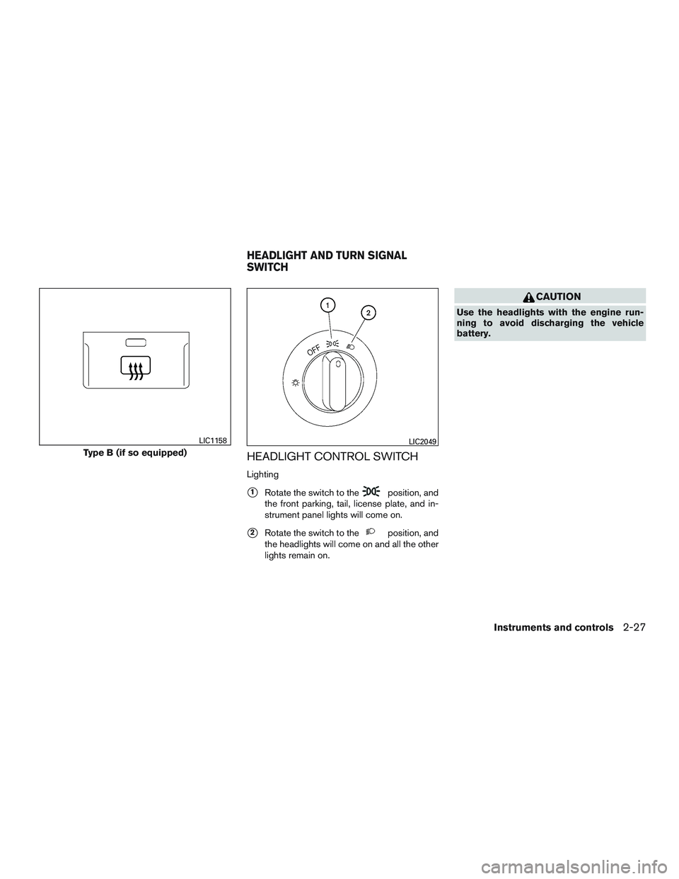
HEADLIGHT CONTROL SWITCH
Lighting
�1Rotate the switch to theposition, and
the front parking, tail, license plate, and in-
strument panel lights will come on.
�2Rotate the switch to theposition, and
the headlights will come on and all the other
lights remain on.
CAUTION
Use the headlights with the engine run-
ning to avoid discharging the vehicle
battery.
Type B (if so equipped)
LIC1158LIC2049
HEADLIGHT AND TURN SIGNAL
SWITCH
Instruments and controls2-27
Page 113 of 380

Headlight beam select
�1To select the high beam function, engage the
low beams, and push the lever forward until it
latches. The high beam lights come on and
the blue
indicator light illuminates.
�2Pull the lever back to return to the low beam.
For additional information, refer to “Head-
light control switch” in this section.
�3Pulling and releasing the lever flashes the
headlight high beams on and off. The low
beams need not be on for this to function.
Battery saver system
If the ignition switch is placed in the OFF position
while the headlight switch is in the
orposition, the headlights will turn off after
a period of time.
After the headlights automatically turn off with the
headlight switch in the
orposition,
the headlights will illuminate again if the headlight
switch is moved to the OFF position and then
turned to the
orposition.
CAUTION
Even though the battery saver feature au-
tomatically turns off the headlights after a
period of time, you should turn the head-
light switch to the OFF position when the
engine is not running to avoid discharging
the vehicle battery.
DAYTIME RUNNING LIGHT SYSTEM
The headlights automatically illuminate at a re-
duced intensity when the engine is started with
the parking brake released. The daytime running
lights operate with the headlight switch in the
OFF position. Turn the headlight switch to
the
orposition for full illumination
when driving at night. If the parking brake is applied before the engine is
started, the daytime running lights do not illumi-
nate. The daytime running lights illuminate when
the parking brake is released. The daytime run-
ning lights will remain on until the ignition switch
is placed in the OFF position.
WARNING
When the daytime running light system is
active, tail lights on your vehicle are not
on. It is necessary at dusk to turn on your
headlights. Failure to do so could cause
an accident injuring yourself and others.
LIC3060
2-28Instruments and controls
Page 115 of 380

To sound the horn, push the center pad area of
the steering wheel.
WARNING
Do not disassemble the horn. Doing so
could affect proper operation of the
supplemental front air bag system. Tam-
pering with the supplemental front air bag
system may result in serious personal
injury.The front seats are warmed by built-in heaters.
1. Start the engine.
2. Push the LO or HI position of the switch, as desired. The indicator light in the switch will
illuminate.
The heater is controlled by a thermostat,
automatically turning the heater on and off.
The indicator light will remain on as long as
the switch is on.
3. When the seat is warmed or before you leave the vehicle, be sure to turn the switch
off.
WARNING
Do not use or allow occupants to use the
seat heater if you or the occupants cannot
monitor elevated seat temperatures or
have an inability to feel pain in body parts
that contact the seat. Use of the seat
heater by such people could result in seri-
ous injury.
CAUTION
●The battery could run down if the seat
heater is operated while the engine is
not running.
● Do not use the seat heater for extended
periods or when no one is using the
seat.
● Do not put anything on the seat which
insulates heat, such as a blanket, cush-
ion, seat cover, etc. Otherwise, the seat
may become overheated.
● Do not place anything hard or heavy on
the seat or pierce it with a pin or similar
object. This may result in damage to the
heater.
● Any liquid spilled on the heated seat
should be removed immediately with a
dry cloth.
LIC2051LIC1543
HORN HEATED SEATS (if so equipped)
2-30Instruments and controls
Page 117 of 380

CAUTION
●Use power outlets with the engine run-
ning to avoid discharging the vehicle
battery.
● Do not attempt to use this while driving.
● Do not use double adapters or more
than one electrical accessory, doing so
could significantly drain the battery of
your vehicle.
WARNING
The rear sonar system is a convenience
but it is not a substitute for proper back-
ing. Always turn and check that it is safe to
do so before backing up. Always back up
slowly.
The rear sonar system is active when the ignition
switch is placed to the ON position and the shift
lever is in R (Reverse) .
When sensors detect obstacles within 5.9 ft
(1.8 m) of the rear bumper, a beeping tone is
emitted. The rear sonar system can be disabled by push-
ing the OFF switch. When the system is disabled,
the indicator light on the switch will illuminate.
Push the switch again to enable the system. The
indicator light will go off.
The system will automatically reset the next time
the ignition switch is turned on.
For additional information, refer to “Rear sonar
system” in the “Starting and driving” section of
this manual.
LIC0471
REAR SONAR SYSTEM OFF SWITCH
(if so equipped)
2-32Instruments and controls

2. Engine oil filler cap (P. 8-11)
3. Engine oil dipstick (P. 8-11)
4. Brake fluid reservoir (P. 8-16)
5. Air cleaner (P. 8-21)
6. Windshield-washer fl")

2. Power steering fluid reservoir (P. 8-15)
3. Engine coolant reservoir (P. 8-9)
4. Brake fluid reservoir (P. 8-16)
5. Air cleaner (P. 8-21)
6. Windshi")