2016 NISSAN NV PASSENGER VAN tow
[x] Cancel search: towPage 34 of 380
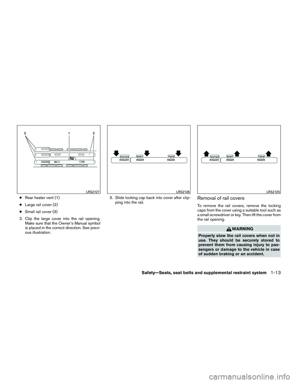
●Rear heater vent (1)
● Large rail cover (2)
● Small rail cover (3)
2. Clip the large cover into the rail opening. Make sure that the Owner’s Manual symbol
is placed in the correct direction. See previ-
ous illustration. 3. Slide locking cap back into cover after clip-
ping into the rail.Removal of rail covers
To remove the rail covers, remove the locking
caps from the cover using a suitable tool such as
a small screwdriver or key. Then lift the cover from
the rail opening.
WARNING
Properly stow the rail covers when not in
use. They should be securely stored to
prevent them from causing injury to pas-
sengers or damage to the vehicle in case
of sudden braking or an accident.
LRS2127LRS2126LRS2125
Safety—Seats, seat belts and supplemental restraint system1-13
Page 45 of 380
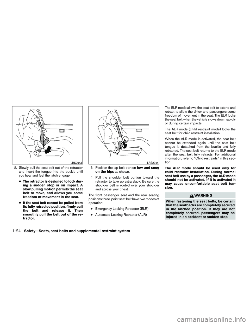
2. Slowly pull the seat belt out of the retractorand insert the tongue into the buckle until
you hear and feel the latch engage.
● The retractor is designed to lock dur-
ing a sudden stop or on impact. A
slow pulling motion permits the seat
belt to move, and allows you some
freedom of movement in the seat.
● If the seat belt cannot be pulled from
its fully retracted position, firmly pull
the belt and release it. Then
smoothly pull the belt out of the re-
tractor. 3. Position the lap belt portion
low and snug
on the hips as shown.
4. Pull the shoulder belt portion toward the retractor to take up extra slack. Be sure the
shoulder belt is routed over your shoulder
and across your chest.
The front passenger seat and the rear seating
positions three-point seat belt have two modes of
operation: ● Emergency Locking Retractor (ELR)
● Automatic Locking Retractor (ALR) The ELR mode allows the seat belt to extend and
retract to allow the driver and passengers some
freedom of movement in the seat. The ELR locks
the seat belt when the vehicle slows down rapidly
or during certain impacts.
The ALR mode (child restraint mode) locks the
seat belt for child restraint installation.
When the ALR mode is activated, the seat belt
cannot be extended again until the seat belt
tongue is detached from the buckle and fully
retracted. The seat belt returns to the ELR mode
after the seat belt fully retracts. For additional
information, refer to “Child restraints” in this sec-
tion.
The ALR mode should be used only for
child restraint installation. During normal
seat belt use by a passenger, the ALR mode
should not be activated. If it is activated it
may cause uncomfortable seat belt ten-
sion.
WARNING
When fastening the seat belts, be certain
that the seatbacks are completely secured
in the latched position. If they are not
completely secured, passengers may be
injured in an accident or sudden stop.
LRS2043LRS2044
1-24Safety—Seats, seat belts and supplemental restraint system
Page 72 of 380
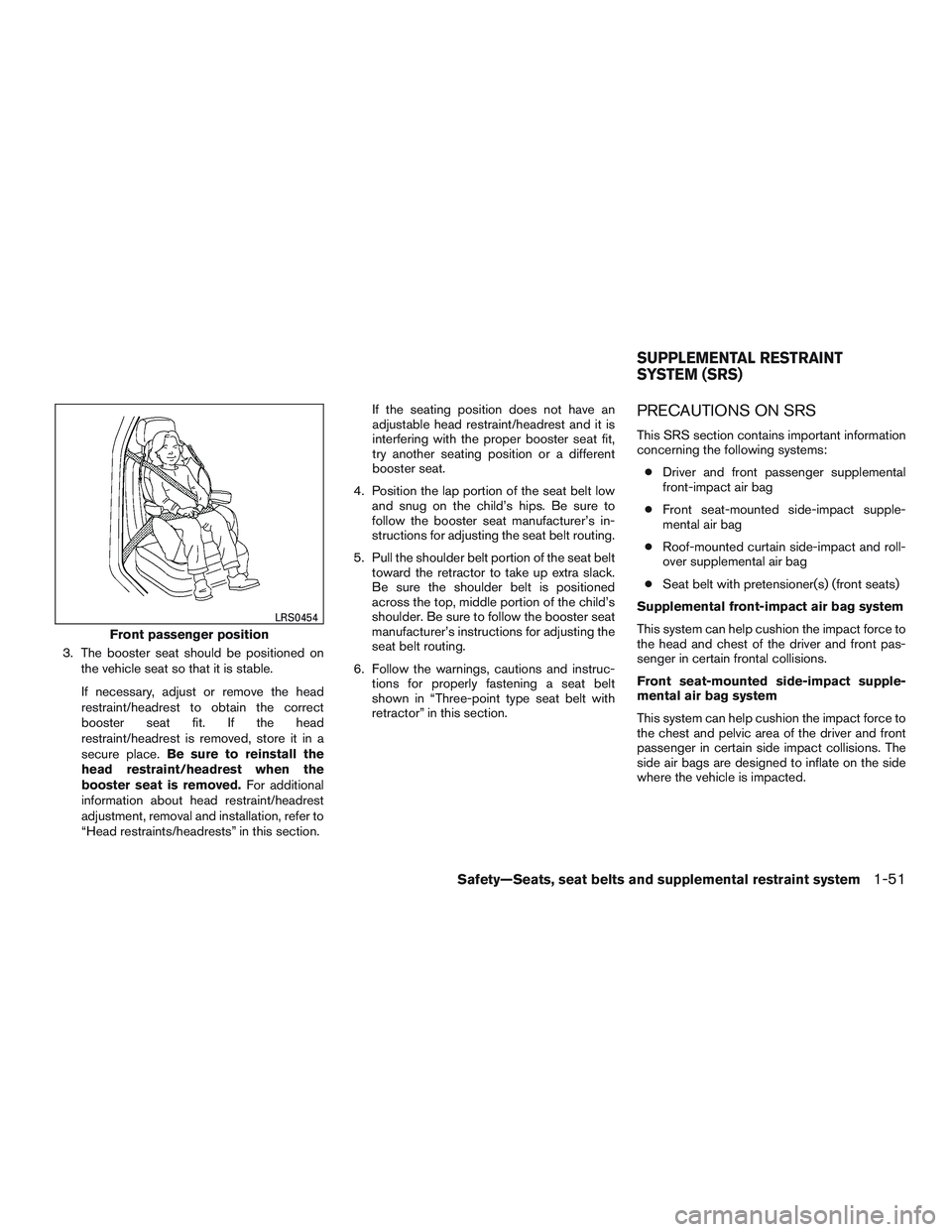
3. The booster seat should be positioned onthe vehicle seat so that it is stable.
If necessary, adjust or remove the head
restraint/headrest to obtain the correct
booster seat fit. If the head
restraint/headrest is removed, store it in a
secure place. Be sure to reinstall the
head restraint/headrest when the
booster seat is removed. For additional
information about head restraint/headrest
adjustment, removal and installation, refer to
“Head restraints/headrests” in this section. If the seating position does not have an
adjustable head restraint/headrest and it is
interfering with the proper booster seat fit,
try another seating position or a different
booster seat.
4. Position the lap portion of the seat belt low and snug on the child’s hips. Be sure to
follow the booster seat manufacturer’s in-
structions for adjusting the seat belt routing.
5. Pull the shoulder belt portion of the seat belt toward the retractor to take up extra slack.
Be sure the shoulder belt is positioned
across the top, middle portion of the child’s
shoulder. Be sure to follow the booster seat
manufacturer’s instructions for adjusting the
seat belt routing.
6. Follow the warnings, cautions and instruc- tions for properly fastening a seat belt
shown in “Three-point type seat belt with
retractor” in this section.
PRECAUTIONS ON SRS
This SRS section contains important information
concerning the following systems:
● Driver and front passenger supplemental
front-impact air bag
● Front seat-mounted side-impact supple-
mental air bag
● Roof-mounted curtain side-impact and roll-
over supplemental air bag
● Seat belt with pretensioner(s) (front seats)
Supplemental front-impact air bag system
This system can help cushion the impact force to
the head and chest of the driver and front pas-
senger in certain frontal collisions.
Front seat-mounted side-impact supple-
mental air bag system
This system can help cushion the impact force to
the chest and pelvic area of the driver and front
passenger in certain side impact collisions. The
side air bags are designed to inflate on the side
where the vehicle is impacted.
Front passenger position
LRS0454
SUPPLEMENTAL RESTRAINT
SYSTEM (SRS)
Safety—Seats, seat belts and supplemental restraint system1-51
Page 88 of 380
17. Rear sonar system OFF switch(if so equipped) (P. 2-32)
Tow mode ON switch (if so equipped)
(P. 2-33)
Front and rear sonar system OFF
switch (if so equipped) (P. 2-33)
Heated seat switch (if so equipped)
(P. 2-30)
Power inverter switch (if so equipped)
(P. 2-31)
18. 12v power outlet (P. 2-34)
19. Ignition switch (P. 5-8)
20. Tilt steering wheel control (P. 3-15)
21. Hood release switch (P. 3-12)
22. Fuse box (P. 8-24)
23. Outside power mirror switch (P. 3-18) Vehicle Dynamic Control (VDC) OFF
switch (P. 2-31)
*: Refer to the separate Navigation System Own-
er’s Manual (if so equipped) .
Refer to the page number indicated in pa-
rentheses for operating details.
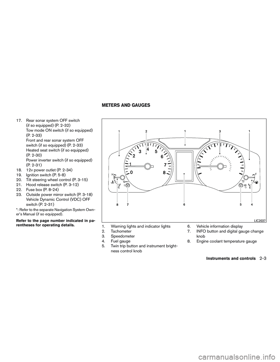
1. Warning lights and indicator lights
2. Tachometer
3. Speedometer
4. Fuel gauge
5. Twin trip button and instrument bright-
ness control knob 6. Vehicle information display
7. INFO button and digital gauge change
knob
8. Engine coolant temperature gauge
LIC2037
METERS AND GAUGES
Instruments and controls2-3
Page 95 of 380
1. With the display turned on, press and holdthe
button for about 13 seconds. The
“C” icon in the compass display will illumi-
nate.
2. Calibrate the compass by driving the vehicle in three complete circles at a maximum
speed of 5 mph (8 km/h).
3. After completing the circles, the display should return to normal.
CAUTION
●Do not install a ski rack, antenna, etc.,
which are attached to the vehicle by
means of a magnet. They affect the op-
eration of the compass.
● When cleaning the mirror, use a paper
towel or similar material dampened
with glass cleaner. Do not spray glass
cleaner directly on the mirror as it may
cause the liquid cleaner to enter the
mirror housing.
2-10Instruments and controls
Page 96 of 380
orAnti-lock Braking System (ABS)
warning lightLow fuel warning lightCruise set switch indicator light
(if so equipped)
Automatic Transmission check warning lightLow tire pressure warning lightHigh beam indicator light (blue)
Automatic Transmission oil temperature
warning lightLow windshield-washer fluid warning light
(if so equipped)Malfunction Indicator Light (MIL)
orBrake warning lightMaster warning lightSecurity indicator light (if so equipped)
Charge warning lightPassenger’s seat belt warning lightSlip indicator light
Door open warning lightSupplemental air bag warning lightTow mode ON indicator light (if so equipped)
Driver’s seat belt warning light and chimeAutomatic Transmission position indicator lightTurn signal/hazard indicator lights
Engine oil pressure warning lightCruise main switch indicator light
(if so equipped)Vehicle Dynamic Control (VDC) OFF indicator
light
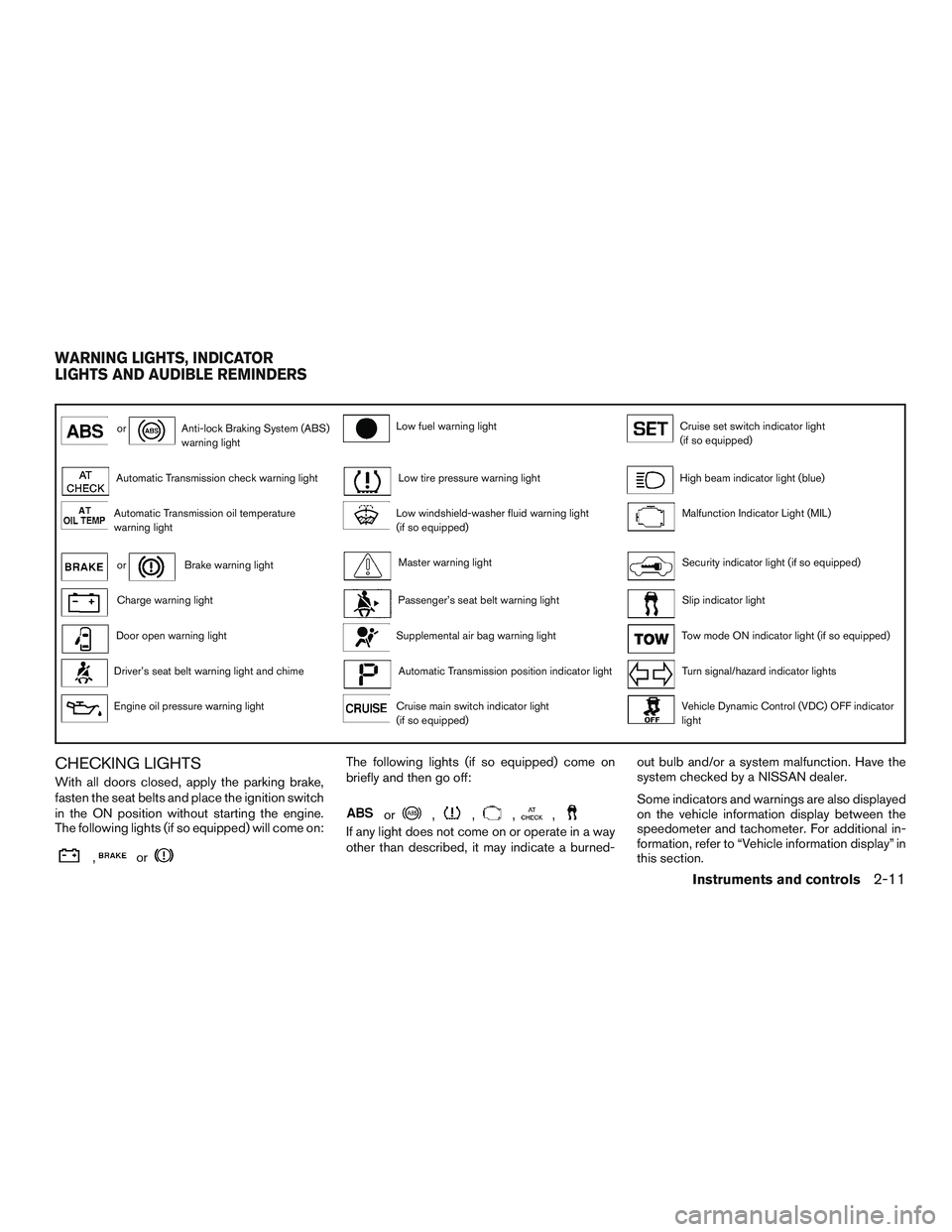
CHECKING LIGHTS
With all doors closed, apply the parking brake,
fasten the seat belts and place the ignition switch
in the ON position without starting the engine.
The following lights (if so equipped) will come on:
,or
The following lights (if so equipped) come on
briefly and then go off:
or,,,,
If any light does not come on or operate in a way
other than described, it may indicate a burned-out bulb and/or a system malfunction. Have the
system checked by a NISSAN dealer.
Some indicators and warnings are also displayed
on the vehicle information display between the
speedometer and tachometer. For additional in-
formation, refer to “Vehicle information display” in
this section.
WARNING LIGHTS, INDICATOR
LIGHTS AND AUDIBLE REMINDERS
Instruments and controls2-11
Page 97 of 380
WARNING LIGHTS
For additional information, refer to “Vehicle infor-
mation display” in this section.
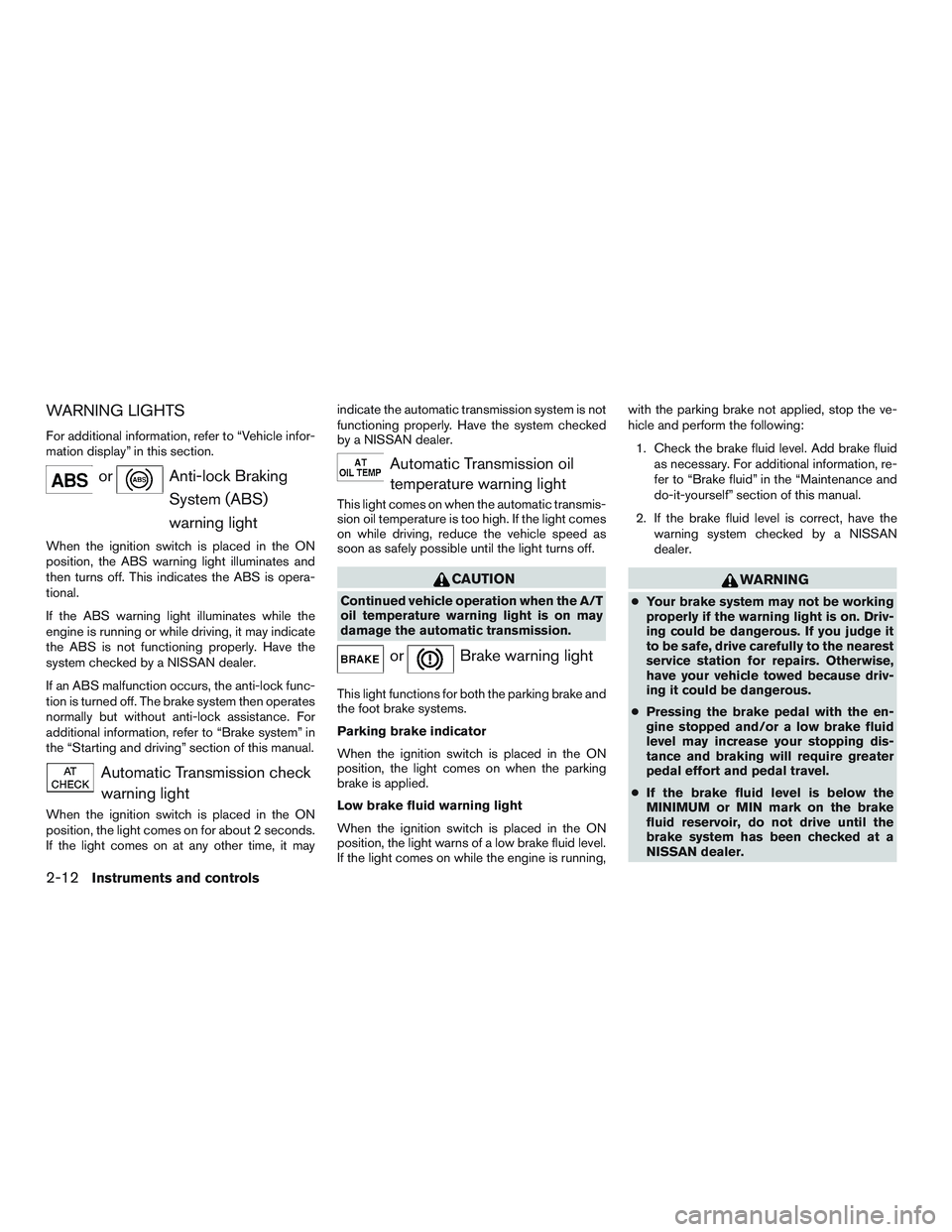
orAnti-lock BrakingSystem (ABS)
warning light
When the ignition switch is placed in the ON
position, the ABS warning light illuminates and
then turns off. This indicates the ABS is opera-
tional.
If the ABS warning light illuminates while the
engine is running or while driving, it may indicate
the ABS is not functioning properly. Have the
system checked by a NISSAN dealer.
If an ABS malfunction occurs, the anti-lock func-
tion is turned off. The brake system then operates
normally but without anti-lock assistance. For
additional information, refer to “Brake system” in
the “Starting and driving” section of this manual.
Automatic Transmission checkwarning light
When the ignition switch is placed in the ON
position, the light comes on for about 2 seconds.
If the light comes on at any other time, it may indicate the automatic transmission system is not
functioning properly. Have the system checked
by a NISSAN dealer.
Automatic Transmission oil
temperature warning light
This light comes on when the automatic transmis-
sion oil temperature is too high. If the light comes
on while driving, reduce the vehicle speed as
soon as safely possible until the light turns off.
CAUTION
Continued vehicle operation when the A/T
oil temperature warning light is on may
damage the automatic transmission.
orBrake warning light
This light functions for both the parking brake and
the foot brake systems.
Parking brake indicator
When the ignition switch is placed in the ON
position, the light comes on when the parking
brake is applied.
Low brake fluid warning light
When the ignition switch is placed in the ON
position, the light warns of a low brake fluid level.
If the light comes on while the engine is running, with the parking brake not applied, stop the ve-
hicle and perform the following:
1. Check the brake fluid level. Add brake fluid as necessary. For additional information, re-
fer to “Brake fluid” in the “Maintenance and
do-it-yourself” section of this manual.
2. If the brake fluid level is correct, have the warning system checked by a NISSAN
dealer.
WARNING
●Your brake system may not be working
properly if the warning light is on. Driv-
ing could be dangerous. If you judge it
to be safe, drive carefully to the nearest
service station for repairs. Otherwise,
have your vehicle towed because driv-
ing it could be dangerous.
● Pressing the brake pedal with the en-
gine stopped and/or a low brake fluid
level may increase your stopping dis-
tance and braking will require greater
pedal effort and pedal travel.
● If the brake fluid level is below the
MINIMUM or MIN mark on the brake
fluid reservoir, do not drive until the
brake system has been checked at a
NISSAN dealer.
2-12Instruments and controls
Page 101 of 380
INDICATOR LIGHTS
For additional information, refer to “Vehicle infor-
mation display” in this section.
Automatic Transmissionposition indicator light
When the ignition switch is placed in the ON
position, this indicator light shows the shift lever
position. For additional information, refer to “Driv-
ing the vehicle” in the “Starting and driving” sec-
tion of this manual.
Cruise main switch indicatorlight (if so equipped)
The light comes on when the cruise control main
switch is pushed. The light goes out when the
main switch is pushed again. When the cruise
main switch indicator light comes on, the cruise
control system is operational.
For additional information, refer to “Cruise con-
trol” in the “Starting and driving” section of this
manual.
Cruise set switch indicatorlight (if so equipped)
The light comes on while the vehicle speed is
controlled by the cruise control system. If the light
blinks while the engine is running, it may indicate the cruise control system is not functioning prop-
erly. Have the system checked by a NISSAN
dealer.
High beam indicator light
(blue)
This blue light comes on when the headlight high
beams are on and goes out when the low beams
are selected.
The high beam indicator light also comes on
when the passing signal is activated.
Malfunction Indicator Light(MIL)
If this indicator light comes on steady or blinks
while the engine is running, it may indicate a
potential emission control malfunction.
The
may also come on steady if the fuel-
filler cap is loose or missing, or if the vehicle runs
out of fuel. Check to make sure the fuel-filler cap
is installed and closed tightly, and that the vehicle
has at least 3 gallons (11.4 liters) of fuel in the
fuel tank.
After a few driving trips, the
light should
turn off if no other potential emission control
system malfunction exists.
When the ignition switch is in the ON position,
sometimes the indicator light may illuminate for
20 seconds and then blink for 10 seconds, with- out the engine running. This is due to a function of
checking the engine control system, and it is not
a malfunction. After a few normal drives, this
function will not occur and the
stays illumi-
nated with the ignition switch in the ON position.
CAUTION
Incorrect setting of the engine control sys-
tem may lead to non-compliance of local
and national emission laws and
regulations.
Operation
The MIL will come on in one of two ways: ● MIL on steady — An emission control system
malfunction has been detected. Check the
fuel-filler cap if the LOOSE FUEL CAP
warning appears in the vehicle information
display. If the fuel-filler cap is loose or miss-
ing, tighten or install the cap and continue to
drive the vehicle. The
light should turn
off after a few driving trips. If the
light
does not turn off after a few driving trips,
have the vehicle inspected by a NISSAN
dealer. You do not need to have your vehicle
towed to the dealer.
2-16Instruments and controls