2016 NISSAN NOTE Shifter
[x] Cancel search: ShifterPage 631 of 3641
CLUTCH PEDALCL-5
< PERIODIC MAINTENANCE >
CEF
G H
I
J
K L
M A
B
CL
N
O P
PERIODIC MAINTENANCE
CLUTCH PEDAL
Inspection and AdjustmentINFOID:0000000012432215
INSPECTION
The Height of Clutch Pedal
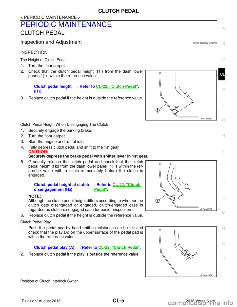
1. Turn the floor carpet.
2. Check that the clutch pedal height (H
1) from the dash lower
panel (1) is within the reference value.
3. Replace clutch pedal if the height is outside the reference value.
Clutch Pedal Height When Disengaging The Clutch
1. Securely engage the parking brake.
2. Turn the floor carpet.
3. Start the engine and run at idle.
4. Fully depress clutch pedal and shift to the 1st gear. CAUTION:
Securely depress the brake pedal with shifter lever in 1st gear.
5. Gradually release the clutch pedal and check that the clutch pedal height (H
2) from the dash lower panel (1) is within the ref-
erence value with a scale immediately before the clutch is
engaged.
NOTE:
Although the clutch pedal height differs according to whether the
clutch gets disengaged or engaged, clutch-engaged case is
regarded as clutch-disengaged case for easier inspection.
6. Replace clutch pedal if the height is outside the reference value.
Clutch Pedal Play
1. Push the pedal pad by hand until a resistance can be felt and check that the play (A) on the upper surface of the pedal pad is
within the reference value.
2. Replace clutch pedal if the play is outside the reference value.
Position of Clutch Interlock Switch
Clutch pedal height
(H
1) : Refer to
CL-22, "
Clutch Pedal".
JPFIA0065ZZ
Clutch pedal height at clutch
disengagement (H
2) : Refer to CL-22, "
Clutch
Pedal".
JPFIA0068ZZ
Clutch pedal play (A) : Refer to
CL-22, "Clutch Pedal".
JPFIA0121ZZ
Revision: August 2015 2016 Versa Note
cardiagn.com
Page 3261 of 3641
![NISSAN NOTE 2016 Service Repair Manual TM-20
< REMOVAL AND INSTALLATION >[5MT: RS5F91R]
CONTROL LINKAGE
CONTROL LINKAGE
Exploded ViewINFOID:0000000012430954
Removal and InstallationINFOID:0000000012430955
REMOVAL
1. Move the shift selecto](/manual-img/5/57363/w960_57363-3260.png "NISSAN NOTE 2016 Service Repair Manual TM-20
< REMOVAL AND INSTALLATION >[5MT: RS5F91R]
CONTROL LINKAGE
CONTROL LINKAGE
Exploded ViewINFOID:0000000012430954
Removal and InstallationINFOID:0000000012430955
REMOVAL
1. Move the shift selecto")
TM-20
< REMOVAL AND INSTALLATION >[5MT: RS5F91R]
CONTROL LINKAGE
CONTROL LINKAGE
Exploded ViewINFOID:0000000012430954
Removal and InstallationINFOID:0000000012430955
REMOVAL
1. Move the shift selector to the neutral position.
2. Remove the battery tray. Refer to
PG-71, "
Removal and Installation (Battery Tray)".
3. Pull out and disconnect cables from shifter lever A and selector lever, using a suitable tool.
4. While pressing the lock of the selector cable in the direction of the arrows shown, remove the selector cable from the cable
mounting bracket.
5. While pressing the lock of the shifter cable in the direction of the arrows shown, remove the shifter cable from the cable mounting
bracket.
6. Remove cable mounting bracket from clutch housing.
7. Pull the shift selector handle upward to remove.
8. Remove center console assembly. Refer to IP-18, "
Removal and
Installation".
9. Pull out and disconnect each cable from the shift selector assembly, using a suitable tool.
1. Shifter lever A 2. Selector lever 3. Selector cable
4. Shifter cable 5. Cable mounting bracket6. Tapping bolt
7. Bracket 8. Grommet9. Shift selector assembly
10. Shift selector 11. Shift selector handle
JPDIC0789GB
JPDIC0793ZZ
Revision: August 2015 2016 Versa Note
cardiagn.com
Page 3262 of 3641
![NISSAN NOTE 2016 Service Repair Manual CONTROL LINKAGETM-21
< REMOVAL AND INSTALLATION > [5MT: RS5F91R]
C
EF
G H
I
J
K L
M A
B
TM
N
O P
a. While pressing the lock of the selector cable in the direction of the arrows shown, remove the selec](/manual-img/5/57363/w960_57363-3261.png "NISSAN NOTE 2016 Service Repair Manual CONTROL LINKAGETM-21
< REMOVAL AND INSTALLATION > [5MT: RS5F91R]
C
EF
G H
I
J
K L
M A
B
TM
N
O P
a. While pressing the lock of the selector cable in the direction of the arrows shown, remove the selec")
CONTROL LINKAGETM-21
< REMOVAL AND INSTALLATION > [5MT: RS5F91R]
C
EF
G H
I
J
K L
M A
B
TM
N
O P
a. While pressing the lock of the selector cable in the direction of the arrows shown, remove the selector cable from the shift
selector assembly.
b. While pressing the lock of the shifter cable in the direction of the arrows shown, remove the shifter cable from the shift selector
assembly.
10. Remove the shift selector assembly.
11. Remove center muffler, exhaust front tube, and heat plate. Refer to EX-5, "
Exploded View".
12. Remove the bracket from the vehicle.
13. Remove the grommet and then remove the shifter cable and selector cable from the vehicle.
INSTALLATION
Installation is in the reverse order of removal.
CAUTION:
• Install each cable without causing in terference with other parts. Do not allow cable to bend less than
120 mm (4.72 in), or exceed 180 degree twist.
• Install boot of each cable without causing interference with other parts. Do not exceed 90 degree twist.
• Fit boot to center console assembly an d the groove on shift selector handle.
• To install the shift selector handle, press it onto the shift selector. CAUTION:
• Do not reuse shift selector handle.
• Be careful with orientation of shift selector handle.
• Bolt hole is not threaded on new clutch housing. Self-tapping bolt is used to attach lock plate to clutch hous-
ing.
CAUTION:
Do not reuse self-tapping bolt.
• Insert each cable until it reaches the cable mounting bracket and shift selector assembly.
• Insert each cable until it reaches the shifter lever A and the selector lever.
• Move the shift selector to the neutral position.
InspectionINFOID:0000000012430956
INSPECTION AFTER INSTALLATION
Shift Selector Handle
Check that the shift selector handle is installed in the right position.
Shifter Cable and Selector Cable
• Pull each cable in the removal direction to check that it does not disconnect from the cable mounting
bracket.
• Pull each cable in the removal direction to check that it does not disconnect from the shift selector assembly.
• Pull grommet in the removal direction to che ck that it does not disconnect from the vehicle.
Shift Selector Assembly and Shift Selector
• Check that there is no unusual noise, binding, bending, looseness, and interference when the shift selector
is moved to each position. If there is a malfuncti on, then repair or replace the malfunctioning part.
• Check that the shift selector smoothl y returns to the neutral position after moving the shift selector from 1st
to 2nd gear and releasing it. If there is a malfunction, then repair or replace the malfunctioning part.
• Check that the shift selector smoothly returns to the neutral position after moving the shift selector from 5th to the reverse gear position and releasing it. If there is a malfunction, then repair or replace the malfunction-
ing part.
JPDIC0793ZZ
Revision: August 2015 2016 Versa Note
cardiagn.com
Page 3264 of 3641
![NISSAN NOTE 2016 Service Repair Manual 5TH MAIN GEAR ASSEMBLYTM-23
< REMOVAL AND INSTALLATION > [5MT: RS5F91R]
C
EF
G H
I
J
K L
M A
B
TM
N
O P
5TH MAIN GEAR ASSEMBLY
Removal and InstallationINFOID:0000000012430959
REMOVAL
1. Move the shift](/manual-img/5/57363/w960_57363-3263.png "NISSAN NOTE 2016 Service Repair Manual 5TH MAIN GEAR ASSEMBLYTM-23
< REMOVAL AND INSTALLATION > [5MT: RS5F91R]
C
EF
G H
I
J
K L
M A
B
TM
N
O P
5TH MAIN GEAR ASSEMBLY
Removal and InstallationINFOID:0000000012430959
REMOVAL
1. Move the shift")
5TH MAIN GEAR ASSEMBLYTM-23
< REMOVAL AND INSTALLATION > [5MT: RS5F91R]
C
EF
G H
I
J
K L
M A
B
TM
N
O P
5TH MAIN GEAR ASSEMBLY
Removal and InstallationINFOID:0000000012430959
REMOVAL
1. Move the shift selector to the 3rd gear position.
2. Disconnect the shifter cable and the selector cable fr om shifter lever A and selector lever. Refer to TM-20,
"Removal and Installation".
CAUTION:
Do not move shifter lever A and selector lever to disconnect each cable.
3. Drain gear oil. Refer to TM-17, "
Draining".
4. Remove fender protector (LH). Refer to EXT-38, "
Removal and Installation".
5. Remove the harness clamp (A) from rear housing (1).
6. Remove rear housing and O-ring. CAUTION:
Remove in direction of input shaft ( ) as shown. Rear
housing gear oil channel is inserted to input shaft center
hole.
7. Remove 5th main gear assembly. Refer to step 5 through 8 of “Disassembly of TRANSAXLE ASSEMBLY”. Refer to TM-30,
"Disassembly".
INSTALLATION
Installation is in the reverse order of removal.
• Shift into 3rd with shifter lever to install the 5th main gear assembly, referring to Step 36 to 39 of “Assemblyof TRANSAXLE ASSEMBLY” Refer to TM-36, "
Assembly".
• Install O-ring and the rear housing to the transaxle case and tighten the bolts to the specified torque. Refer to TM-26, "
Exploded View".
CAUTION:
• Do not reuse O-ring.
• Do not pinch O-ring when installing rear housing.
• Refill gear oil. Refer to TM-17, "
Refilling".
InspectionINFOID:0000000012430960
INSPECTION AFTER INSTALLATION
• Check the operation of the control linkage. Refer to TM-21, "Inspection".
• Check the gear oil level and for oil leaks. Refer to TM-17, "
Inspection".
JPDIC0734ZZ
SCIA1709J
Revision: August 2015 2016 Versa Note
cardiagn.com
Page 3271 of 3641
![NISSAN NOTE 2016 Service Repair Manual TM-30
< UNIT DISASSEMBLY AND ASSEMBLY >[5MT: RS5F91R]
TRANSAXLE ASSEMBLY
Disassembly
INFOID:0000000012430965
1. Remove drain plug and gasket from clutch housing using suitable tool, and drain gear oil](/manual-img/5/57363/w960_57363-3270.png "NISSAN NOTE 2016 Service Repair Manual TM-30
< UNIT DISASSEMBLY AND ASSEMBLY >[5MT: RS5F91R]
TRANSAXLE ASSEMBLY
Disassembly
INFOID:0000000012430965
1. Remove drain plug and gasket from clutch housing using suitable tool, and drain gear oil")
TM-30
< UNIT DISASSEMBLY AND ASSEMBLY >[5MT: RS5F91R]
TRANSAXLE ASSEMBLY
Disassembly
INFOID:0000000012430965
1. Remove drain plug and gasket from clutch housing using suitable tool, and drain gear oil.
2. Remove filler plug and gasket from transaxle case.
3. Remove rear housing and O-ring. CAUTION:
Remove in direction of input shaft ( ) as shown. Rear
housing oil channel is inserte d to input shaft center hole.
4. Move the shifter lever A (1) to the 3rd gear position. NOTE:
• If it is not moved to the 3rd gear position, transaxle case can-
not be removed from clutch housing.
• The 3rd gear position means that shifter lever A is fully rotated
clockwise and it is returned approximately 10 degrees.
1. Differential side bearing outer race 2. Differential side bearing 3. Final drive
: Replace the parts as a set.
JPDIC0481ZZ
SCIA1709J
PCIB1524E
Revision: August 2015 2016 Versa Note
cardiagn.com
Page 3282 of 3641
![NISSAN NOTE 2016 Service Repair Manual TRANSAXLE ASSEMBLYTM-41
< UNIT DISASSEMBLY AND ASSEMBLY > [5MT: RS5F91R]
C
EF
G H
I
J
K L
M A
B
TM
N
O P
30. Move the shifter lever A (1) to the 3rd gear position. NOTE:
• If it is not moved to the](/manual-img/5/57363/w960_57363-3281.png "NISSAN NOTE 2016 Service Repair Manual TRANSAXLE ASSEMBLYTM-41
< UNIT DISASSEMBLY AND ASSEMBLY > [5MT: RS5F91R]
C
EF
G H
I
J
K L
M A
B
TM
N
O P
30. Move the shifter lever A (1) to the 3rd gear position. NOTE:
• If it is not moved to the")
TRANSAXLE ASSEMBLYTM-41
< UNIT DISASSEMBLY AND ASSEMBLY > [5MT: RS5F91R]
C
EF
G H
I
J
K L
M A
B
TM
N
O P
30. Move the shifter lever A (1) to the 3rd gear position. NOTE:
• If it is not moved to the 3rd gear position, transaxle case can-not be installed to clutch housing.
• The 3rd gear position means that shifter lever A is fully rotated clockwise and it is returned approximately 10 degrees.
31. Apply recommended sealant to transaxle case mating surface of clutch housing.
CAUTION:
• Use Genuine Silicone RTV or equivalent. Refer to GI-22,
"Recommended Chemical Products and Sealants".
• Do not allow old Silicone RTV, moisture, oil, or foreign matter to remain on mating surface.
• Check that mating surface is not damaged.
• Apply a continuous bead of Si licone RTV to the mating surface.
32. Install transaxle case to clutch hous ing. If it is difficult to install,
slightly rotate shifter lever A counterclockwise, and then install.
CAUTION:
• Do not damage Silicone RTV bead with transaxle case or
other objects during installation.
• Be careful to align the lever of 5th-reverse fork rod with
reverse gear groove.
33. Rotate input shaft so that bearing and shaft fit each other, and then tighten transaxle bolts ( ) to the specified torque.
34. Apply recommended sealant to position switch thread and check ball plug thread. Install to transaxle case and tighten to specified
torque.
CAUTION:
• Use Genuine Silicone RTV or equivalent. Refer to GI-22,
"Recommended Chemical Products and Sealants".
• Do not allow old Silicone RTV, moisture, oil, or foreign matter to remain on thread.
35. Apply gear oil to mainshaft spline.
36. Install 5th main gear (1) to mainshaft, using a suitable bolt (A) [M10 x 1.0] and a suitable nut (B).
PCIB1524E
(1) : Selector
(2) : Shift fork
PCIB1553E
JPDIC0610ZZ
PCIB1554E
Revision: August 2015 2016 Versa Note
cardiagn.com
Page 3284 of 3641
![NISSAN NOTE 2016 Service Repair Manual TRANSAXLE ASSEMBLYTM-43
< UNIT DISASSEMBLY AND ASSEMBLY > [5MT: RS5F91R]
C
EF
G H
I
J
K L
M A
B
TM
N
O P
e. Set 5th-reverse shift fork (1) to 5th-reverse coupling sleeve, and then install them to 5th-](/manual-img/5/57363/w960_57363-3283.png "NISSAN NOTE 2016 Service Repair Manual TRANSAXLE ASSEMBLYTM-43
< UNIT DISASSEMBLY AND ASSEMBLY > [5MT: RS5F91R]
C
EF
G H
I
J
K L
M A
B
TM
N
O P
e. Set 5th-reverse shift fork (1) to 5th-reverse coupling sleeve, and then install them to 5th-")
TRANSAXLE ASSEMBLYTM-43
< UNIT DISASSEMBLY AND ASSEMBLY > [5MT: RS5F91R]
C
EF
G H
I
J
K L
M A
B
TM
N
O P
e. Set 5th-reverse shift fork (1) to 5th-reverse coupling sleeve, and then install them to 5th-reverse fork rod and input shaft.
CAUTION:
Do not reuse nut.
CAUTION:
• Be careful with the orient ation of 5th-reverse coupling
sleeve.
• Replace 5th-reverse synchronizer hub and 5th-reverse coupling sleeve as a set.
• Replace 5th-reverse shift fork and 5th-reverse fork rod as a set.
f. Check that the shifter lever A is in the 3rd position. Press 5th-
reverse shift fork (1) and move shifter lever A to 5th gear.
g. Tighten bolt (B) to the specified torque.
h. Tighten nut (C) to the specified torque. CAUTION:
Do not reuse nut.
i. Install retaining pin to 5th-reverse shift fork, using suitable tool. CAUTION:
Do not reuse retaining pin.
39. Move shifter lever A (1) to the neutral position.
40. Install O-ring to rear housing. CAUTION:
Do not reuse O-ring.
(A) : Suitable tool
(B) : Bolt
(C) : Nut
JPDIC0532ZZ
: 5th input gear side
JPDIC0409ZZ
(A) : Suitable tool
JPDIC0532ZZ
SCIA7130E
Revision: August 2015 2016 Versa Note
cardiagn.com
Page 3338 of 3641
![NISSAN NOTE 2016 Service Repair Manual DIAGNOSIS SYSTEM (TCM)TM-97
< SYSTEM DESCRIPTION > [CVT: RE0F11A]
C
EF
G H
I
J
K L
M A
B
TM
N
O P
STRDWNSW (On/Off) ו Displays the operation status of the paddle shifter
(down switch).
• It is](/manual-img/5/57363/w960_57363-3337.png "NISSAN NOTE 2016 Service Repair Manual DIAGNOSIS SYSTEM (TCM)TM-97
< SYSTEM DESCRIPTION > [CVT: RE0F11A]
C
EF
G H
I
J
K L
M A
B
TM
N
O P
STRDWNSW (On/Off) ו Displays the operation status of the paddle shifter
(down switch).
• It is")
DIAGNOSIS SYSTEM (TCM)TM-97
< SYSTEM DESCRIPTION > [CVT: RE0F11A]
C
EF
G H
I
J
K L
M A
B
TM
N
O P
STRDWNSW (On/Off) ו Displays the operation status of the paddle shifter
(down switch).
• It is displayed although not equipped.
STRUPSW (On/Off) ו Displays the operation status of the paddle shifter (up
switch).
• It is displayed although not equipped.
DOWNLVR (On/Off) ו Displays the operation status of the selector lever
(down switch).
• It is displayed although not equipped.
UPLVR (On/Off) ו Displays the operation status of the selector lever (up
switch).
• It is displayed although not equipped.
NONMMODE (On/Off) ו Displays if the selector lever position is not at the man-
ual shift gate.
• It is displayed although not equipped.
MMODE (On/Off) ו Displays if the selector lever position is at the manual
shift gate.
• It is displayed although not equipped.
INDLRNG (On/Off) Displays the transmission status of the shift position (L
position) signal transmitted through CAN communica-
tion.
INDDRNG (On/Off) Displays the transmission status of the shift position (D
position) signal transmitted through CAN communica-
tion.
INGNRNG (On/Off) Displays the transmission status of the shift position (N
position) signal transmitted through CAN communica-
tion.
INGRRNG (On/Off) Displays the transmission status of the shift position (R
position) signal transmitted through CAN communica-
tion.
INGPRNG (On/Off) Displays the transmission status of the shift position (P
position) signal transmitted through CAN communica-
tion.
CVT LAMP (On/Off) Displays the transmission status of the OD OFF indicator
lamp signal transmitted through CAN communication.
SPORT MODE IND (On/Off) Displays the transmission status of the OD OFF indicator
lamp signal transmitted through CAN communication.
MMODE IND (On/Off) • Displays the transmission status of the manual mode
signal transmitted through CAN communication.
• It is displayed although not equipped.
VDC ON (On/Off) ו Displays the reception status of the VDC (ESP) oper-
ation signal received through CAN communication.
• It is displayed although not equipped.
TCS ON (On/Off) ו Displays the reception status of the TCS operation sig-
nal received through CAN communication.
• It is displayed although not equipped.
ABS FAIL SIGNAL (On/Off) ×Displays the reception status of the ABS malfunction sig-
nal received through CAN communication.
ABS ON (On/Off) ×Displays the reception status of the ABS operation signal
received through CAN communication.
RANGE ×Displays the gear position recognized by TCM.
M GEAR POS ×Display the target gear of manual mode
Monitored item
(Unit)Monitor item selection
Remarks
MAIN SIG-
NALS ECU IN-
PUT SIG-
NALS
Revision: August 2015 2016 Versa Note
cardiagn.com