2016 NISSAN NOTE Crash Zone Sensor
[x] Cancel search: Crash Zone SensorPage 834 of 3641
![NISSAN NOTE 2016 Service Repair Manual RADIATOR CORE SUPPORTDLK-145
< REMOVAL AND INSTALLATION > [WITH INTELLIGENT KEY SYSTEM]
C
D
E
F
G H
I
J
L
M A
B
DLK
N
O P
3. Remove washer tube inlet clip (A).
4. Remove radiator cap adapter bracket b](/manual-img/5/57363/w960_57363-833.png "NISSAN NOTE 2016 Service Repair Manual RADIATOR CORE SUPPORTDLK-145
< REMOVAL AND INSTALLATION > [WITH INTELLIGENT KEY SYSTEM]
C
D
E
F
G H
I
J
L
M A
B
DLK
N
O P
3. Remove washer tube inlet clip (A).
4. Remove radiator cap adapter bracket b")
RADIATOR CORE SUPPORTDLK-145
< REMOVAL AND INSTALLATION > [WITH INTELLIGENT KEY SYSTEM]
C
D
E
F
G H
I
J
L
M A
B
DLK
N
O P
3. Remove washer tube inlet clip (A).
4. Remove radiator cap adapter bracket bolt (A) and radiator reser- voir tank bolt (B).
5. Remove horn. Refer to HRN-6, "
Removal and Installation".
6. Remove crash zone sensor. Refer to SR-24, "
Removal and Installation".
7. Remove hood lock assembly. Refer to DLK-165, "
HOOD LOCK : Removal and Installation".
8. Release hood lock release cable clips from radi ator core support upper using a suitable tool.
9. Remove upper air guide. Refer to DLK-144, "
Exploded View".
10. Remove air guide (LH/RH). Refer to DLK-144, "
Exploded View".
11. Release all harness connector clips from radiator core support upper using a suitable tool.
12. Remove bolts (A) and radiator core support upper.
INSTALLATION
Installation is in the reverse order of removal.
CAUTION:
After installation, perform hood assembl y adjustment procedure. Refer to DLK-141, "
HOOD ASSEM-
BLY : Adjustment".
RADIATOR CORE SUPPORT LOWER
RADIATOR CORE SUPPORT LOWE R : Removal and InstallationINFOID:0000000012430092
REMOVAL
1. Remove radiator core support upper. Refer to DLK-144, "RADIATOR CORE SUPPORT UPPER :
Removal and Installation".
2. Reposition the radiator and condenser.
AWKIA2567ZZ
JMKIA8027ZZ
AWKIA2568ZZ
Revision: August 2015 2016 Versa Note
cardiagn.com
Page 962 of 3641
![NISSAN NOTE 2016 Service Repair Manual RADIATOR CORE SUPPORTDLK-273
< REMOVAL AND INSTALLATION > [WITHOUT INTELLIGENT KEY SYSTEM]
C
D
E
F
G H
I
J
L
M A
B
DLK
N
O P
3. Remove washer tube inlet clip (A).
4. Remove radiator cap adapter bracke](/manual-img/5/57363/w960_57363-961.png "NISSAN NOTE 2016 Service Repair Manual RADIATOR CORE SUPPORTDLK-273
< REMOVAL AND INSTALLATION > [WITHOUT INTELLIGENT KEY SYSTEM]
C
D
E
F
G H
I
J
L
M A
B
DLK
N
O P
3. Remove washer tube inlet clip (A).
4. Remove radiator cap adapter bracke")
RADIATOR CORE SUPPORTDLK-273
< REMOVAL AND INSTALLATION > [WITHOUT INTELLIGENT KEY SYSTEM]
C
D
E
F
G H
I
J
L
M A
B
DLK
N
O P
3. Remove washer tube inlet clip (A).
4. Remove radiator cap adapter bracket bolt (A) and radiator reser- voir tank bolt (B).
5. Remove horn. Refer to HRN-6, "
Removal and Installation".
6. Remove crash zone sensor. Refer to SR-24, "
Removal and Installation".
7. Remove hood lock assembly. Refer to DLK-292, "
HOOD LOCK : Removal and Installation".
8. Release hood lock release cable clips from radi ator core support upper using a suitable tool.
9. Remove upper air guide. Refer to DLK-272, "
Exploded View".
10. Remove air guide (LH/RH). Refer to DLK-272, "
Exploded View".
11. Release all harness connector clips from radiator core support upper using a suitable tool.
12. Remove bolts (A) and radiator core support upper.
INSTALLATION
Installation is in the reverse order of removal.
CAUTION:
After installation, perform hood assembl y adjustment procedure. Refer to DLK-269, "
HOOD ASSEM-
BLY : Adjustment".
RADIATOR CORE SUPPORT LOWER
RADIATOR CORE SUPPORT LOWE R : Removal and InstallationINFOID:0000000012430238
REMOVAL
1. Remove radiator core support upper. Refer to DLK-272, "RADIATOR CORE SUPPORT UPPER :
Removal and Installation".
2. Reposition the radiator and condenser.
AWKIA2567ZZ
JMKIA8027ZZ
AWKIA2568ZZ
Revision: August 2015 2016 Versa Note
cardiagn.com
Page 2633 of 3641

PG-46
< WIRING DIAGRAM >
HARNESS
D3 E4 Y/2 : Crash zone sensorE1 E42 B/2: IPDM E/R (Intelligent power distribution
module engine room)
E4 E5 B/2 : Cooling fan motor (With CVT)E2 E43 B/6: IPDM E/R (Intelligent power distribution
module engine room)
E2 E8 W/24 : To F8 F2 E44 BR/8: IPDM E/R (Intelligent power distribution
module engine room)
E3 E9 BR/2 : Fusible link b o x ( B a t t e r y )E 1 E 4 5 B R / 1 2: IPDM E/R (Intelligent power distribution
module engine room)
E2 E10 GR/2 : Fusible link box (Battery) F2 E46 W/24: IPDM E/R (Intelligent power distribution
module engine room)
G 2 E 1 5 — : B o d y g r o u n d F 2 E 4 7 W / 1 6: IPDM E/R (Intelligent power distribution
module engine room)
F 2 E 1 6 B / 3 2 : E C M B 3 E 5 0 B R / 2 : W a s h e r f l u i d l e v e l s w i t c h
F4 E17 B/3 : Refrigerant pressure sensor E3 E51 B/2 : Front wheel sensor LH
C4 E18 BR/1 : Horn C4 E52 B/2 : Front wheel sensor RH
E 2 E 1 9 W / 6 : To F 3 3 G 4 E 5 3 B / 2 : F r o n t f o g l a m p L H
C 4 E 2 0 B / 1 : H o r n B 5 E 5 4 B / 2 : F r o n t f o g l a m p R H
A2 E24 — : Body ground E2 E55 GR/12 : To F55
G3 E25 B/3 : Front combination lamp LH G3 E62 L/4 : Cooling fan relay
A3 E26 B/3 : Front combination lamp RH C3 E63 GR/4 : Heated oxygen sensor 2
G2 E27 B/2 : Front combination lamp LH C4 E64 L/4 : Heated seat relay
A2 E28 B/2 : Front combinati on lamp RHG5 E69 B/2 : Ambient sensor
F4 E29 GR/3 : Front combination lamp LH E5 E70 BR/3 : Intelligent Key warning buzzer
B3 E30 GR/3 : Front combination lamp RH F5 E71 B/4 : Front camera
E3 E31 GR/4 : Cooling fan motor (With CVT) G3 E72 L/4 : Active grille shutter relay
E4 E32 W/2 : Cooling fan motor (With CVT) Front fog lamp sub harness
B2 E33 B/38 : ABS actuator and electric unit (Control
unit) E5 E302 B/4 : To E35
E5 E35 B/4 : To E302 F5 E303 B/4 : Active grille shutter
E1 E39 W/3 : Horn relay F5 E303 B/4 : Active grille shutter
Revision: August 2015 2016 Versa Note
cardiagn.com
Page 3018 of 3641

SRC-1
RESTRAINTS
C
DE
F
G
I
J
K L
M
SECTION SRC
A
B
SRC
N
O P
CONTENTS
SRS AIRBAG CONTROL SYSTEM
PRECAUTION ....... ........................................4
PRECAUTIONS .............................................. .....4
Precaution for Supplemental Restraint System
(SRS) "AIR BAG" and "SEAT BELT PRE-TEN-
SIONER" ............................................................. ......
4
Service ......................................................................4
SYSTEM DESCRIPTION ..............................5
COMPONENT PARTS ................................... .....5
Component Parts Location .................................. ......5
Driver Air Bag Module ...............................................6
Front Passenger Air Bag Module ..............................6
Front Side Air Bag Module .................................. ......7
Side Curtain Air Bag Module .....................................7
Front Seat Belt Pre-tensioner ....................................7
Air Bag Diagnosis Sensor Unit ..................................7
Crash Zone Sensor ...................................................8
Front Side Air Bag Satellite Sensor ...........................8
Rear Side Air Bag Satellite Sensor ...........................8
Front Door Satellite Sensor .......................................8
SRS Component Connectors ....................................8
SYSTEM .............................................................10
SRS AIR BAG SYSTEM ............................................10
SRS AIR BAG SYSTEM : System Description ... ....10
OCCUPANT CLASSIFICATION SYSTEM ............ ....10
OCCUPANT CLASSIFICATION SYSTEM : Sys-
tem Description .......................................................
11
SEAT BELT WARNING LAMP SYSTEM .............. ....12
SEAT BELT WARNING LAMP SYSTEM : System
Description ..............................................................
12
DIAGNOSIS SYSTEM (AIR BAG) .....................14
Description .......................................................... ....14
On Board Diagnosis Function .................................14
Trouble Diagnosis with CONSULT ..........................16
CONSULT Function (AIR BAG) ..............................16
ECU DIAGNOSIS INFORMATION ..............17
DIAGNOSIS SENSOR UNIT .............................17
DTC Index ........................................................... ....17
Flash Code Index ....................................................21
WIRING DIAGRAM ......................................25
SRS AIR BAG SYSTEM ...................................25
Wiring Diagram .................................................... ....25
BASIC INSPECTION ...................................36
DIAGNOSIS AND REPAIR WORK FLOW .......36
Work Flow ............................................................ ....36
INSPECTION AND ADJUSTMENT ..................39
ADDITIONAL SERVICE WHEN REPLACING
CONTROL UNIT .................................................... ....
39
ADDITIONAL SERVICE WHEN REPLACING
CONTROL UNIT : Description .................................
39
ADDITIONAL SERVICE WHEN REPLACING
CONTROL UNIT : Special Repair Requirement ......
39
ZERO POINT RESET ............................................. ....39
ZERO POINT RESET : Description .........................39
ZERO POINT RESET : Special Repair Require-
ment .........................................................................
39
INTERMITTENT INCIDENT ..............................41
Inspection Procedure ..............................................41
DTC/CIRCUIT DIAGNOSIS .........................42
B0001, B0002 DRIVER AIRBAG MODULE .....42
DTC Logic ............................................................ ....42
Diagnosis Procedure ...............................................43
B0010, B0011 PASSENGER AIRBAG MOD-
ULE ....................................................................
45
DTC Logic ................................................................45
Diagnosis Procedure ...............................................45
Revision: August 2015 2016 Versa Note
cardiagn.com
Page 3019 of 3641

SRC-2
B0020 SIDE AIRBAG MODULE LH ..................47
Description ........................................................... ...47
DTC Logic ...............................................................47
Diagnosis Procedure ..............................................47
B0028 SIDE AIRBAG MODULE RH .................49
Description ........................................................... ...49
DTC Logic ...............................................................49
Diagnosis Procedure ..............................................49
B0021 SIDE CURTAIN AIR BAG MODULE LH
...
51
DTC Logic ............................................................ ...51
Diagnosis Procedure ..............................................51
B0029 SIDE CURTAIN AIR BAG MODULE
RH ......................................................................
53
DTC Logic ............................................................ ...53
Diagnosis Procedure ..............................................53
B1430 SEAT BELT PRE-TENSIONER .............55
DTC Logic ............................................................ ...55
Diagnosis Procedure ..............................................55
B1431 SEAT BELT PRE-TENSIONER .............57
DTC Logic ............................................................ ...57
Diagnosis Procedure ..............................................57
B1428 SEAT BELT BUCKLE SWITCH LH .......59
Description ........................................................... ...59
DTC Logic ...............................................................59
Diagnosis Procedure ..............................................59
B1429 SEAT BELT BUCKLE SWITCH RH ......61
Description ........................................................... ...61
DTC Logic ...............................................................61
Diagnosis Procedure ..............................................61
B0094 CRASH ZONE SENSOR ........................63
DTC Logic ............................................................ ...63
Diagnosis Procedure ..............................................63
B0093 FRONT DOOR SATELLITE SENSOR
LH .......................................................................
65
DTC Logic ............................................................ ...65
Diagnosis Procedure ..............................................65
B0098 FRONT DOOR SATELLITE SENSOR
RH ......................................................................
67
DTC Logic ............................................................ ...67
Diagnosis Procedure ..............................................67
B1500 DOOR SATELLITE SENSOR ................69
DTC Logic ............................................................ ...69
Diagnosis Procedure ..............................................69
B0091 FRONT SIDE AIR BAG SATELLITE
SENSOR LH ......................................................
71
Description ........................................................... ...71
DTC Logic ...............................................................71
Diagnosis Procedure ..............................................72
B0096 FRONT SIDE AIR BAG SATELLITE
SENSOR RH ......................................................
74
Description ........................................................... ...74
DTC Logic ...............................................................74
Diagnosis Procedure ...............................................75
B0092 REAR SIDE AIR BAG SATELLITE
SENSOR LH ......................................................
77
Description ..............................................................77
DTC Logic ...............................................................77
Diagnosis Procedure ...............................................78
B0097 REAR SIDE AIR BAG SATELLITE
SENSOR RH ......................................................
80
Description ........................................................... ...80
DTC Logic ...............................................................80
Diagnosis Procedure ...............................................81
B00A0 OCS SYSTEM .................................... ...83
Description ........................................................... ...83
DTC Logic ...............................................................83
Diagnosis Procedure ...............................................84
B14XX AIR BAG DIAGNOSIS SENSOR UNIT ...86
Description ........................................................... ...86
DTC Logic ...............................................................86
Diagnosis Procedure ...............................................86
B00D2 FRONT PASSENGER AIR BAG ON
INDICATOR .......................................................
88
DTC Logic ............................................................ ...88
Diagnosis Procedure ...............................................88
B00D5 FRONT PASSENGER AIR BAG OFF
INDICATOR .......................................................
90
DTC Logic ............................................................ ...90
Diagnosis Procedure ...............................................90
B142A IGNITION VOLTAGE .............................92
Description ........................................................... ...92
DTC Logic ...............................................................92
Diagnosis Procedure ...............................................92
U1000 CAN COMM CIRCUIT ............................94
Description ........................................................... ...94
DTC Logic ...............................................................94
Diagnosis Procedure ...............................................94
U1010 CONTROL UNIT (CAN) .........................95
Description ........................................................... ...95
DTC Logic ...............................................................95
Diagnosis Procedure ...............................................95
B142X COLLISION DETECTION ......................96
Description ........................................................... ...96
DTC Logic ...............................................................96
Diagnosis Procedure ...............................................96
SYMPTOM DIAGNOSIS ............................97
Revision: August 2015 2016 Versa Note
cardiagn.com
Page 3023 of 3641
SRC-6
< SYSTEM DESCRIPTION >
COMPONENT PARTS
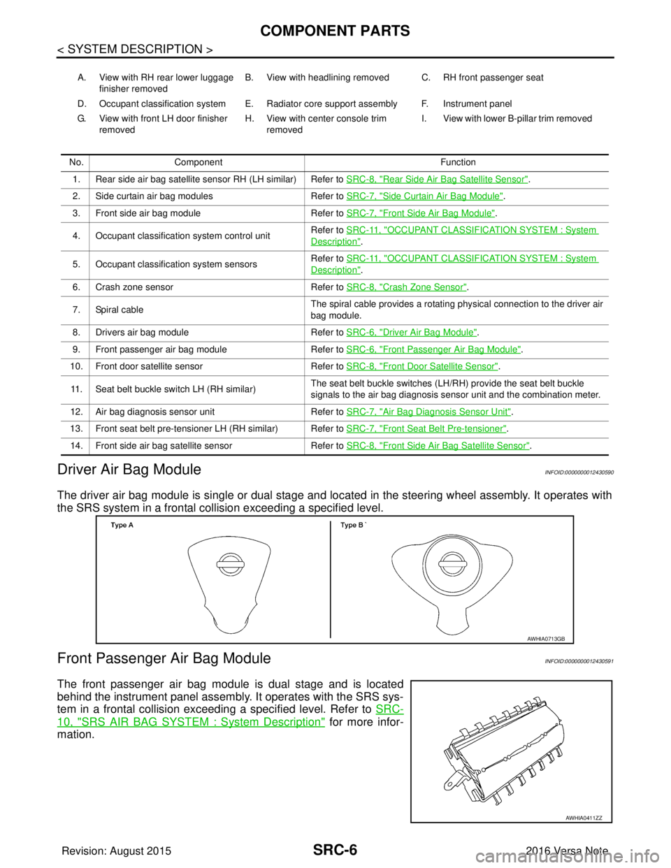
Driver Air Bag Module
INFOID:0000000012430590
The driver air bag module is single or dual stage and located in the steering wheel assembly. It operates with
the SRS system in a frontal collision exceeding a specified level.
Front Passenger Air Bag ModuleINFOID:0000000012430591
The front passenger air bag module is dual stage and is located
behind the instrument panel assembly. It operates with the SRS sys-
tem in a frontal collision exceeding a specified level. Refer to SRC-
10, "SRS AIR BAG SYSTEM : System Description" for more infor-
mation.
A. View with RH rear lower luggage
finisher removed B. View with headlining removed C. RH front passenger seat
D. Occupant classification system E. Radiator core support assembly F. Instrument panel
G. View with front LH door finisher removed H. View with center console trim
removed I. View with lower B-pillar trim removed
No. Component Function
1. Rear side air bag satellite sensor RH (LH similar) Refer to SRC-8, "
Rear Side Air Bag Satellite Sensor".
2. Side curtain air bag modules Refer to SRC-7, "
Side Curtain Air Bag Module".
3. Front side air bag module Refer to SRC-7, "
Front Side Air Bag Module".
4. Occupant classification system control unit Refer to SRC-11, "
OCCUPANT CLASSIFICATION SYSTEM : System
Description".
5. Occupant classification system sensors Refer to SRC-11, "
OCCUPANT CLASSIFICATION SYSTEM : System
Description".
6. Crash zone sensor Refer to SRC-8, "
Crash Zone Sensor".
7. Spiral cable The spiral cable provides a rotating physical connection to the driver air
bag module.
8. Drivers air bag module Refer to SRC-6, "
Driver Air Bag Module".
9. Front passenger air bag module Refer to SRC-6, "
Front Passenger Air Bag Module".
10. Front door satellite sensor Refer to SRC-8, "
Front Door Satellite Sensor".
11. Seat belt buckle switch LH (RH similar) The seat belt buckle switches (LH/RH) provide the seat belt buckle
signals to the air bag diagnosis sensor unit and the combination meter.
12. Air bag diagnosis sensor unit Refer to SRC-7, "
Air Bag Diagnosis Sensor Unit".
13. Front seat belt pre-tensioner LH (RH similar) Refer to SRC-7, "
Front Seat Belt Pre-tensioner".
14. Front side air bag satellite sensor Refer to SRC-8, "
Front Side Air Bag Satellite Sensor".
AWHIA0713GB
AWHIA0411ZZ
Revision: August 2015 2016 Versa Note
cardiagn.com
Page 3025 of 3641

SRC-8
< SYSTEM DESCRIPTION >
COMPONENT PARTS
Crash Zone Sensor
INFOID:0000000012430596
The crash zone sensor is located in front of the radiator. The crash
zone sensor sends signals to the air bag diagnosis sensor unit dur-
ing a frontal collision. This sensor may be identified by a yellow con-
nector.
Front Side Air Bag Satellite SensorINFOID:0000000012430597
The front side air bag satellite sensors are located on the front center
pillar LH and RH next to the seat belt pretensioners. The front side
air bag satellite sensors send signals to the air bag diagnosis sensor
unit during a side collision. These sensors may be identified by yel-
low connectors.
Rear Side Air Bag Satellite SensorINFOID:0000000012430598
The rear side air bag satellite sensors are located behind the lug-
gage side lower finisher LH and RH. The rear side air bag satellite
sensors send signals to the air bag diagnosis sensor unit during a
side collision. These sensors may be identified by yellow connec-
tors.
Front Door Satellite SensorINFOID:0000000012430599
The front door satellite sensors are located in the driver and passen-
ger doors. The front door satellite sensors send signals to the air bag
diagnosis sensor unit during a side collision. These sensors may be
identified by yellow connectors.
SRS Component ConnectorsINFOID:0000000012430600
DIRECT CONNECT
The following SRS components use direct-connect style harness connectors.
AWHIA0537ZZ
AWHIA0544ZZ
AWHIA0543ZZ
AWHIA0546ZZ
Revision: August 2015 2016 Versa Note
cardiagn.com
Page 3036 of 3641
![NISSAN NOTE 2016 Service Repair Manual DIAGNOSIS SENSOR UNITSRC-19
< ECU DIAGNOSIS INFORMATION >
C
DE
F
G
I
J
K L
M A
B
SRC
N
O P
SEAT BELT BUCKLE SW LH CIRCUIT [OPEN]
B1428LH seat belt buckle switch circuit is open. Refer to
SRC-59, "Di](/manual-img/5/57363/w960_57363-3035.png "NISSAN NOTE 2016 Service Repair Manual DIAGNOSIS SENSOR UNITSRC-19
< ECU DIAGNOSIS INFORMATION >
C
DE
F
G
I
J
K L
M A
B
SRC
N
O P
SEAT BELT BUCKLE SW LH CIRCUIT [OPEN]
B1428LH seat belt buckle switch circuit is open. Refer to
SRC-59, \"Di")
DIAGNOSIS SENSOR UNITSRC-19
< ECU DIAGNOSIS INFORMATION >
C
DE
F
G
I
J
K L
M A
B
SRC
N
O P
SEAT BELT BUCKLE SW LH CIRCUIT [OPEN]
B1428LH seat belt buckle switch circuit is open. Refer to
SRC-59, "Diag-
nosis Procedure".
SEAT BELT BUCKLE SW LH CIRCUIT [VB-SHORT] LH seat belt buckle switch circuit is shorted
to a power supply circuit.
SEAT BELT BUCKLE SW LH CIRCUIT [GND-SHORT] LH seat belt buckle switch circuit is shorted
to ground.
SEAT BELT BUCKLE SW LH CIRCUIT [UNDEFINED] LH seat belt buckle switch circuit malfunc-
tion.
SEAT BELT BUCKLE SW RH CIRCUIT [OPEN]
B1429RH seat belt buckle switch circuit is open. Refer to
SRC-61, "
Diag-
nosis Procedure".
SEAT BELT BUCKLE SW RH CIRCUIT [VB-SHORT] RH seat belt buckle switch circuit is shorted
to a power supply circuit.
SEAT BELT BUCKLE SW RH CIRCUIT [GND-SHORT] RH seat belt buckle switch circuit is shorted
to ground.
SEAT BELT BUCKLE SW RH CIRCUIT [UNDEFINED] RH seat belt buckle switch circuit malfunc-
tion.
CRASH ZONE SENSOR [SENSOR FAIL]
B0094Crash zone sensor has malfunctioned. Refer to
SRC-63, "
Diag-
nosis Procedure".
CRASH ZONE SENSOR [COMM FAIL] Crash zone sensor communication error.
CRASH ZONE SENSOR [DISCONNECT] Crash zone sensor is disconnected.
CRASH ZONE SENSOR [UNMATCH] Crash zone sensor is out of specification.
CRASH ZONE SENSOR [GND-SHORT] Crash zone sensor circuit is shorted to
ground.
DOOR SATELLITE SENSOR LH [SENSOR FAIL]
B0093Front door satellite sensor LH has malfunc-
tioned.
Refer to SRC-65, "
Diag-
nosis Procedure".
DOOR SATELLITE SENSOR LH [COMM FAIL] Front door satellite sensor LH communica-
tion error.
DOOR SATELLITE SENSOR LH [DISCONNECT] Front door satellite sensor LH is disconnect-
ed.
DOOR SATELLITE SENSOR LH [UNMATCH] Front door satellite sensor LH is out of spec-
ification.
DOOR SATELLITE SENSOR LH [GND-SHORT] Front door satellite sensor LH circuit is
shorted to ground.
DOOR SATELLITE SENSOR RH [SENSOR FAIL]
B0098Front door satellite sensor RH has malfunc-
tioned.
Refer to SRC-67, "
Diag-
nosis Procedure".
DOOR SATELLITE SENSOR RH [COMM FAIL] Front door satellite sensor RH communica-
tion error.
DOOR SATELLITE SENSOR RH [DISCONNECT] Front door satellite sensor RH is discon-
nected.
DOOR SATELLITE SENSOR RH [UNMATCH] Front door satellite sensor RH is out of spec-
ification.
DOOR SATELLITE SENSOR RH [GND-SHORT] Front door satellite sensor RH circuit is
shorted to ground.
DOOR SATELLITE SENSOR [LOWER LIMIT ERR]
B1500Lower limit value malfunction of front door
satellite sensor LH or RH.
Refer to SRC-69, "
Diag-
nosis Procedure".
DOOR SATELLITE SENSOR [UPPER LIMIT ERR] Upper limit value malfunction of front door
satellite sensor LH or RH.
DOOR SATELLITE SENSOR
[PERFRM ERR/INCRCT OPE] Malfunction of front door satellite sensor LH
or RH.
CONSULT name DTC DTC detecting condition Repair order
Revision: August 2015
2016 Versa Note
cardiagn.com