Page 2778 of 3641

POWER SUPPLY AND GROUND CIRCUITWT-35
< DTC/CIRCUIT DIAGNOSIS >
C
DF
G H
I
J
K L
M A
B
WT
N
O P
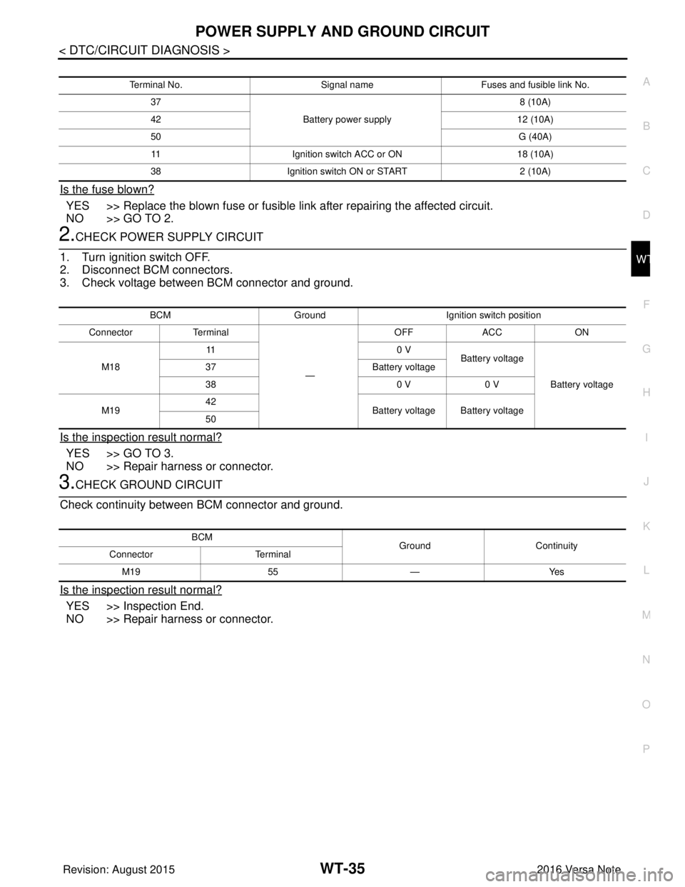
Is the fuse blown?
YES >> Replace the blown fuse or fusible link after repairing the affected circuit.
NO >> GO TO 2.
2.CHECK POWER SUPPLY CIRCUIT
1. Turn ignition switch OFF.
2. Disconnect BCM connectors.
3. Check voltage between BCM connector and ground.
Is the inspection result normal?
YES >> GO TO 3.
NO >> Repair harness or connector.
3.CHECK GROUND CIRCUIT
Check continuity between BCM connector and ground.
Is the inspection result normal?
YES >> Inspection End.
NO >> Repair harness or connector.
Terminal No. Signal nameFuses and fusible link No.
37 Battery power supply 8 (10A)
42 12 (10A)
50 G (40A)
11 Ignition switch ACC or ON 18 (10A)
38 Ignition switch ON or START 2 (10A)
BCMGround Ignition switch position
Connector Terminal
—OFF
ACC ON
M18 11
0 V
Battery voltage
Battery voltage
37
Battery voltage
38 0 V0 V
M19 42
Battery voltage Battery voltage
50
BCM GroundContinuity
Connector Terminal
M19 55—Yes
Revision: August 2015 2016 Versa Note
cardiagn.com
Page 3011 of 3641
![NISSAN NOTE 2016 Service Repair Manual SEC-154
< DTC/CIRCUIT DIAGNOSIS >[WITHOUT INTELLIGENT KEY SYSTEM]
POWER SUPPLY AND GROUND CIRCUIT
POWER SUPPLY AND GROUND CIRCUIT
BCM
BCM : Diagnosis ProcedureINFOID:0000000012542538
Regarding Wiring NISSAN NOTE 2016 Service Repair Manual SEC-154
< DTC/CIRCUIT DIAGNOSIS >[WITHOUT INTELLIGENT KEY SYSTEM]
POWER SUPPLY AND GROUND CIRCUIT
POWER SUPPLY AND GROUND CIRCUIT
BCM
BCM : Diagnosis ProcedureINFOID:0000000012542538
Regarding Wiring](/manual-img/5/57363/w960_57363-3010.png)
SEC-154
< DTC/CIRCUIT DIAGNOSIS >[WITHOUT INTELLIGENT KEY SYSTEM]
POWER SUPPLY AND GROUND CIRCUIT
POWER SUPPLY AND GROUND CIRCUIT
BCM
BCM : Diagnosis ProcedureINFOID:0000000012542538
Regarding Wiring Diagram information, refer to
BCS-117, "Wiring Diagram".
1.CHECK FUSES AND FUSIBLE LINK
Check that the following fuses and fusible link are not blown.
Is the fuse blown?
YES >> Replace the blown fuse or fusible link after repairing the affected circuit.
NO >> GO TO 2.
2.CHECK POWER SUPPLY CIRCUIT
1. Turn ignition switch OFF.
2. Disconnect BCM connectors.
3. Check voltage between BCM connector and ground.
Is the inspection result normal?
YES >> GO TO 3.
NO >> Repair harness or connector.
3.CHECK GROUND CIRCUIT
Check continuity between BCM connector and ground.
Is the inspection result normal?
YES >> Inspection End.
NO >> Repair harness or connector.
Terminal No. Signal nameFuses and fusible link No.
37 Battery power supply 8 (10A)
42 12 (10A)
50 G (40A)
11 Ignition switch ACC or ON 18 (10A)
38 Ignition switch ON or START 2 (10A)
BCMGround Ignition switch position
Connector Terminal
—OFF
ACC ON
M18 11
0 V
Battery voltage
Battery voltage
37
Battery voltage
38 0 V0 V
M19 42
Battery voltage Battery voltage
50
BCM GroundContinuity
Connector Terminal
M19 55—Yes
Revision: August 2015 2016 Versa Note
cardiagn.com
Page 3549 of 3641

WCS-34
< DTC/CIRCUIT DIAGNOSIS >
POWER SUPPLY AND GROUND CIRCUIT
DTC/CIRCUIT DIAGNOSIS
POWER SUPPLY AND GROUND CIRCUIT
COMBINATION METER (TYPE A)
COMBINATION METER (TYPE A) : Diagnosis ProcedureINFOID:0000000012542990
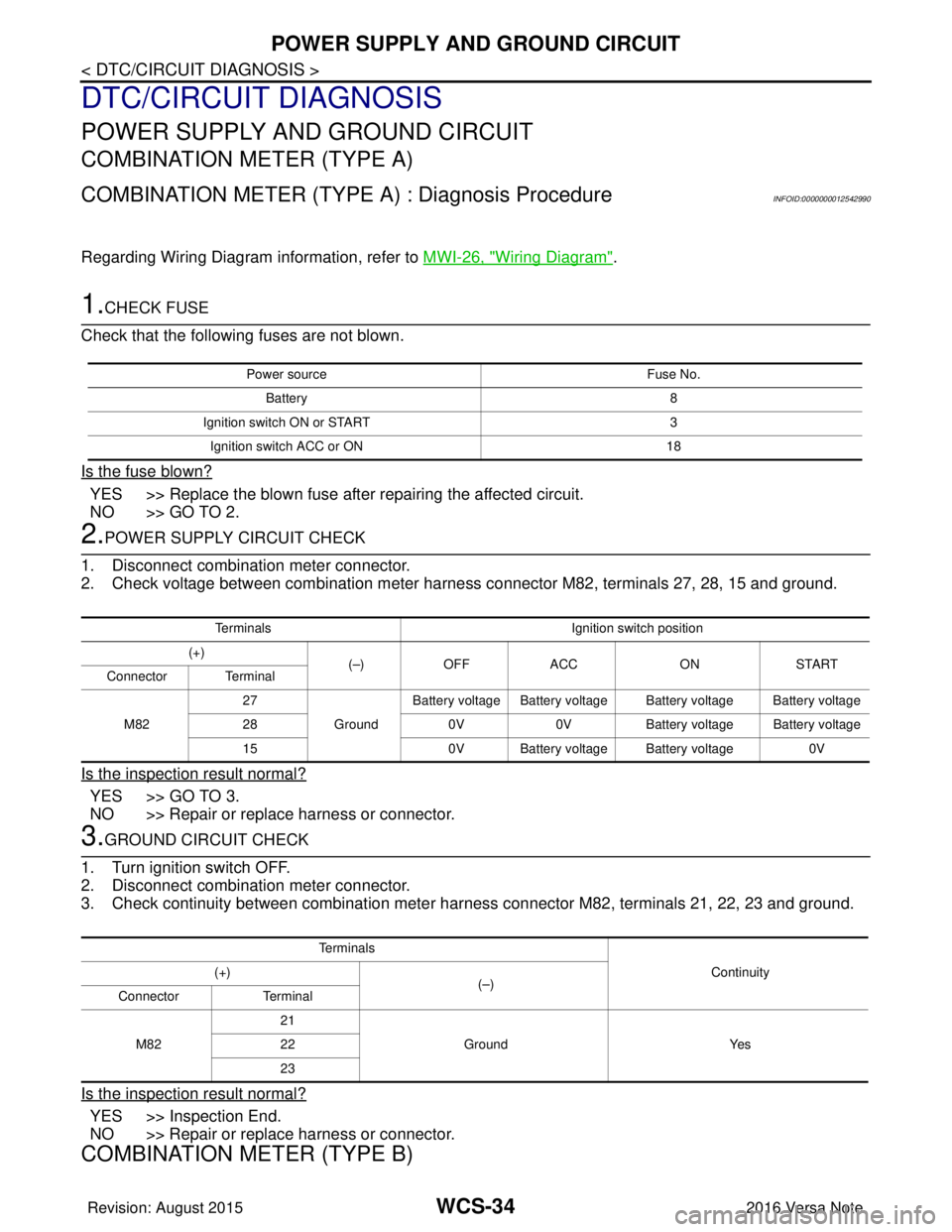
Regarding Wiring Diagram information, refer to MWI-26, "Wiring Diagram".
1.CHECK FUSE
Check that the following fuses are not blown.
Is the fuse blown?
YES >> Replace the blown fuse after repairing the affected circuit.
NO >> GO TO 2.
2.POWER SUPPLY CIRCUIT CHECK
1. Disconnect combination meter connector.
2. Check voltage between combination meter harness connector M82, terminals 27, 28, 15 and ground.
Is the inspection result normal?
YES >> GO TO 3.
NO >> Repair or replace harness or connector.
3.GROUND CIRCUIT CHECK
1. Turn ignition switch OFF.
2. Disconnect combination meter connector.
3. Check continuity between combination meter har ness connector M82, terminals 21, 22, 23 and ground.
Is the inspection result normal?
YES >> Inspection End.
NO >> Repair or replace harness or connector.
COMBINATION METER (TYPE B)
Power source Fuse No.
Battery 8
Ignition switch ON or START 3
Ignition switch ACC or ON 18
TerminalsIgnition switch position
(+) (–)OFF ACC ONSTART
Connector Terminal
M82 27
GroundBattery voltage Battery voltage Battery voltage Battery voltage
28 0V0VBattery voltage Battery voltage
15 0V Battery voltage Battery voltage 0V
Te r m i n a l s
Continuity
(+)
(–)
Connector Terminal
M82 21
Ground Yes
22
23
Revision: August 2015 2016 Versa Note
cardiagn.com
Page 3550 of 3641

WCS
POWER SUPPLY AND GROUND CIRCUITWCS-35
< DTC/CIRCUIT DIAGNOSIS >
C
DE
F
G H
I
J
K L
M B A
O P
COMBINATION METER (TYPE B) : Diagnosis ProcedureINFOID:0000000012542991
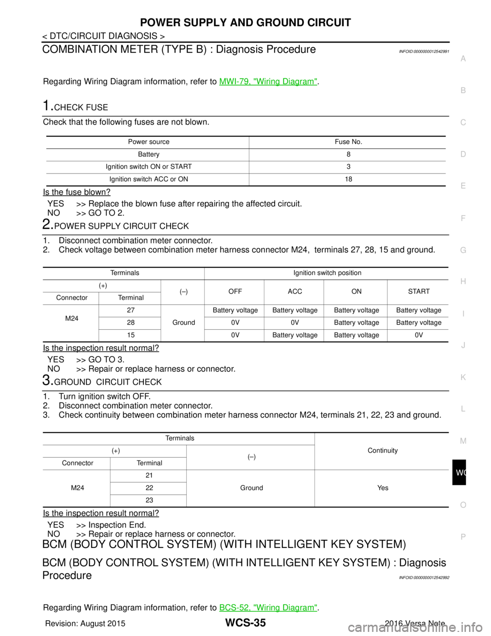
Regarding Wiring Diagram information, refer to MWI-79, "Wiring Diagram".
1.CHECK FUSE
Check that the following fuses are not blown.
Is the fuse blown?
YES >> Replace the blown fuse after repairing the affected circuit.
NO >> GO TO 2.
2.POWER SUPPLY CIRCUIT CHECK
1. Disconnect combination meter connector.
2. Check voltage between combination meter harness connector M24, terminals 27, 28, 15 and ground.
Is the inspection result normal?
YES >> GO TO 3.
NO >> Repair or replace harness or connector.
3.GROUND CIRCUIT CHECK
1. Turn ignition switch OFF.
2. Disconnect combination meter connector.
3. Check continuity between combination meter harness connector M24, terminals 21, 22, 23 and ground.
Is the inspection result normal?
YES >> Inspection End.
NO >> Repair or replace harness or connector.
BCM (BODY CONTROL SYSTEM) (W ITH INTELLIGENT KEY SYSTEM)
BCM (BODY CONTROL SYSTEM) (WITH IN TELLIGENT KEY SYSTEM) : Diagnosis
Procedure
INFOID:0000000012542992
Regarding Wiring Diagram information, refer to BCS-52, "Wiring Diagram".
Power source Fuse No.
Battery 8
Ignition switch ON or START 3
Ignition switch ACC or ON 18
TerminalsIgnition switch position
(+) (–)OFF ACC ONSTART
Connector Terminal
M24 27
GroundBattery voltage Battery voltage Battery voltage Battery voltage
28 0V0VBattery voltage Battery voltage
15 0V Battery voltage Battery voltage 0V
Te r m i n a l s
Continuity
(+)
(–)
Connector Terminal
M24 21
Ground Yes
22
23
Revision: August 2015 2016 Versa Note
cardiagn.com
Page 3551 of 3641

WCS-36
< DTC/CIRCUIT DIAGNOSIS >
POWER SUPPLY AND GROUND CIRCUIT
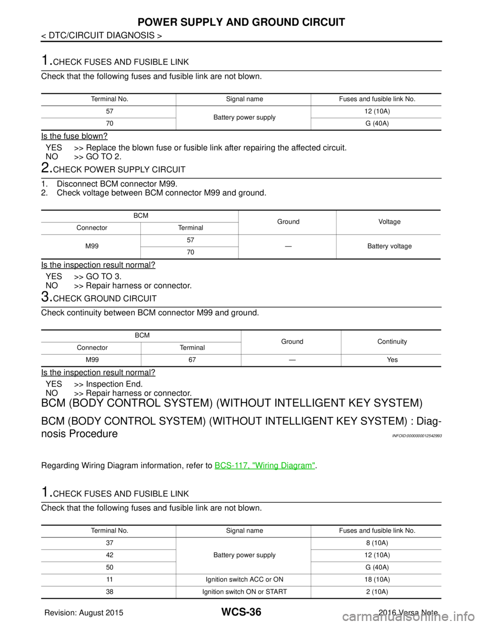
1.CHECK FUSES AND FUSIBLE LINK
Check that the following fuses and fusible link are not blown.
Is the fuse blown?
YES >> Replace the blown fuse or fusible link after repairing the affected circuit.
NO >> GO TO 2.
2.CHECK POWER SUPPLY CIRCUIT
1. Disconnect BCM connector M99.
2. Check voltage between BCM connector M99 and ground.
Is the inspection result normal?
YES >> GO TO 3.
NO >> Repair harness or connector.
3.CHECK GROUND CIRCUIT
Check continuity between BCM connector M99 and ground.
Is the inspection result normal?
YES >> Inspection End.
NO >> Repair harness or connector.
BCM (BODY CONTROL SYSTEM) (WIT HOUT INTELLIGENT KEY SYSTEM)
BCM (BODY CONTROL SYSTEM) (WITHOUT INTELLIGENT KEY SYSTEM) : Diag-
nosis Procedure
INFOID:0000000012542993
Regarding Wiring Diagram information, refer to BCS-117, "Wiring Diagram".
1.CHECK FUSES AND FUSIBLE LINK
Check that the following fuses and fusible link are not blown.
Terminal No. Signal nameFuses and fusible link No.
57 Battery power supply 12 (10A)
70 G (40A)
BCM
Ground Voltage
Connector Terminal
M99 57
— Battery voltage
70
BCM GroundContinuity
Connector Terminal
M99 67—Yes
Terminal No. Signal nameFuses and fusible link No.
37 Battery power supply 8 (10A)
42 12 (10A)
50 G (40A)
11 Ignition switch ACC or ON 18 (10A)
38 Ignition switch ON or START 2 (10A)
Revision: August 2015 2016 Versa Note
cardiagn.com
Page 3600 of 3641
WIPER AND WASHER FUSEWW-35
< DTC/CIRCUIT DIAGNOSIS >
C
DE
F
G H
I
J
K
M A
B
WW
N
O P
DTC/CIRCUIT DIAGNOSIS
WIPER AND WASHER FUSE
DescriptionINFOID:0000000012433213
Diagnosis ProcedureINFOID:0000000012433214
1. CHECK FUSES
Check that the following fuses are not blown.
Is the fuse blown?
YES >> Replace the fuse after repairing the affected circuit.
NO >> Inspection End.
Component CapacityFuse No. Location
Front wiper motor 30A39IPDM E/R
Front and rear washer motor 10A6Fuse block (J/B)
Component CapacityFuse No. Location
Front wiper motor 30A39IPDM E/R
Front and rear washer motor 10A6Fuse block (J/B)
Revision: August 2015 2016 Versa Note
cardiagn.com