2016 NISSAN NOTE wiring
[x] Cancel search: wiringPage 2129 of 3641
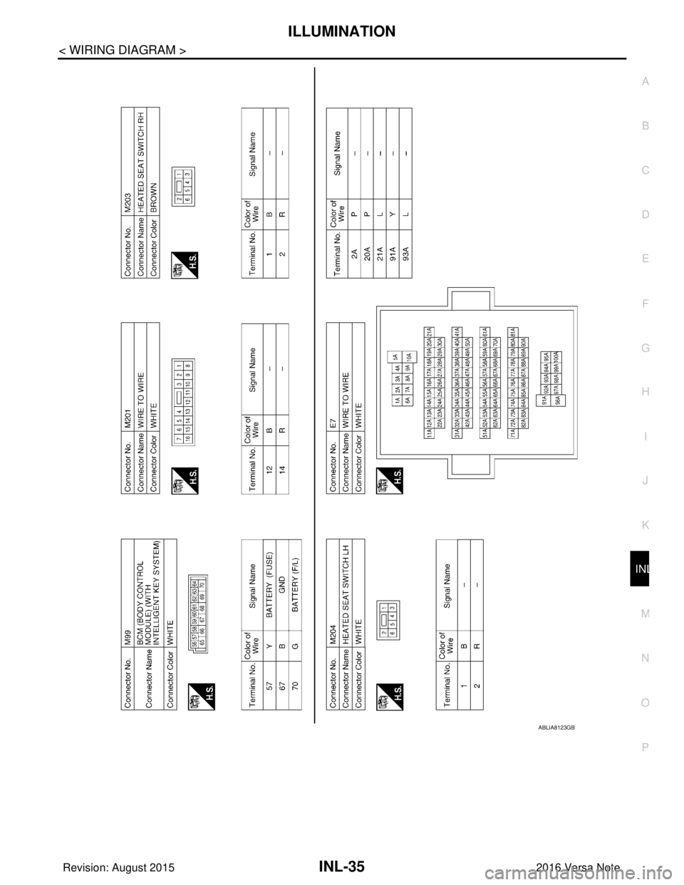
ILLUMINATIONINL-35
< WIRING DIAGRAM >
C
DE
F
G H
I
J
K
M A
B
INL
N
O P
ABLIA8123GB
Revision: August 2015 2016 Versa Note
cardiagn.com
Page 2130 of 3641
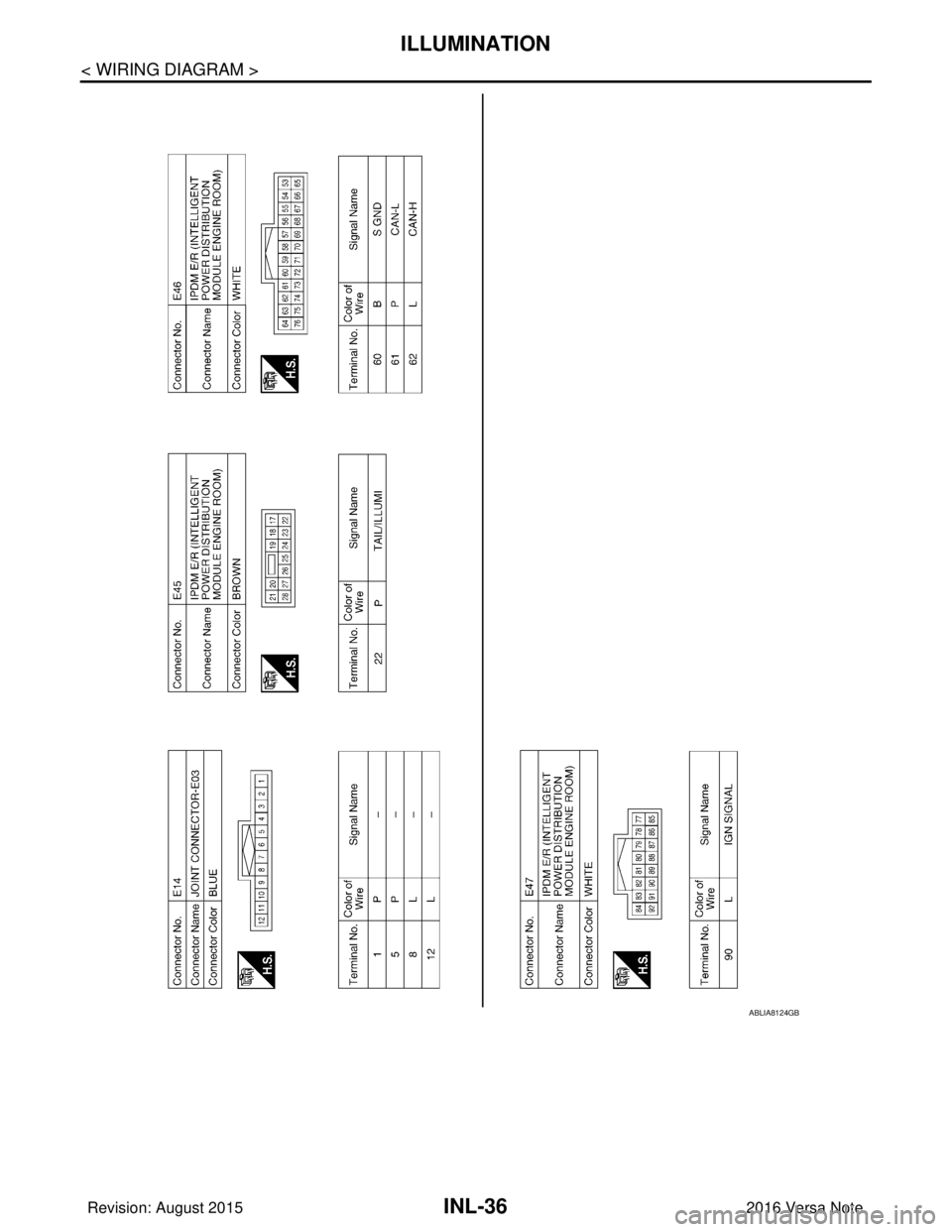
INL-36
< WIRING DIAGRAM >
ILLUMINATION
ABLIA8124GB
Revision: August 20152016 Versa Note
cardiagn.com
Page 2133 of 3641
POWER SUPPLY AND GROUND CIRCUITINL-39
< DTC/CIRCUIT DIAGNOSIS >
C
DE
F
G H
I
J
K
M A
B
INL
N
O P
DTC/CIRCUIT DIAGNOSIS
POWER SUPPLY AND GROUND CIRCUIT
BCM (BODY CONTROL SYSTEM) (W ITH INTELLIGENT KEY SYSTEM)
BCM (BODY CONTROL SYSTEM) (WITH IN TELLIGENT KEY SYSTEM) : Diagnosis
Procedure
INFOID:0000000012542978
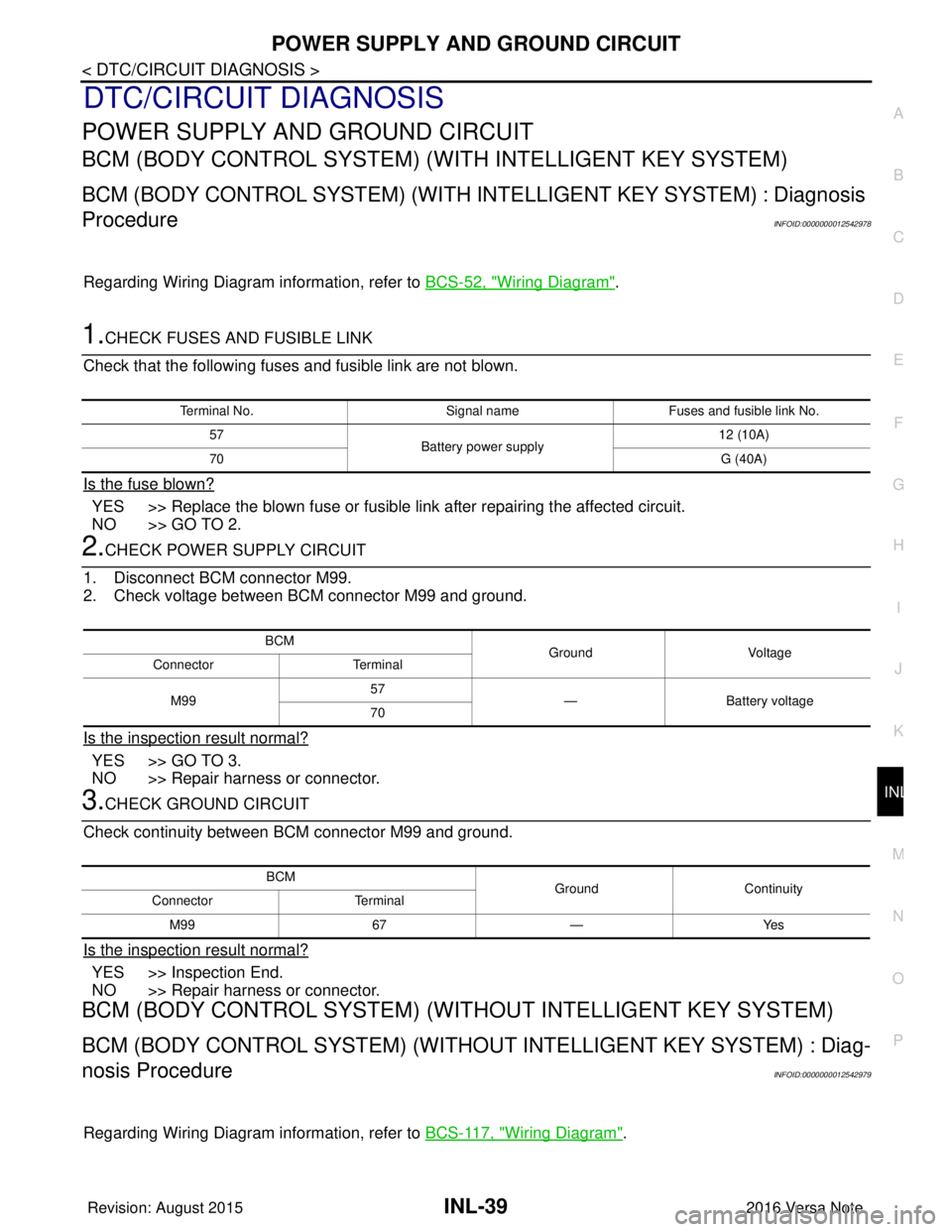
Regarding Wiring Diagram information, refer to BCS-52, "Wiring Diagram".
1.CHECK FUSES AND FUSIBLE LINK
Check that the following fuses and fusible link are not blown.
Is the fuse blown?
YES >> Replace the blown fuse or fusible link after repairing the affected circuit.
NO >> GO TO 2.
2.CHECK POWER SUPPLY CIRCUIT
1. Disconnect BCM connector M99.
2. Check voltage between BCM connector M99 and ground.
Is the inspection result normal?
YES >> GO TO 3.
NO >> Repair harness or connector.
3.CHECK GROUND CIRCUIT
Check continuity between BCM connector M99 and ground.
Is the inspection result normal?
YES >> Inspection End.
NO >> Repair harness or connector.
BCM (BODY CONTROL SYSTEM) (WIT HOUT INTELLIGENT KEY SYSTEM)
BCM (BODY CONTROL SYSTEM) (WITHOUT INTELLIGENT KEY SYSTEM) : Diag-
nosis Procedure
INFOID:0000000012542979
Regarding Wiring Diagram information, refer to BCS-117, "Wiring Diagram".
Terminal No.Signal nameFuses and fusible link No.
57 Battery power supply 12 (10A)
70 G (40A)
BCM
Ground Voltage
Connector Terminal
M99 57
— Battery voltage
70
BCM GroundContinuity
Connector Terminal
M99 67—Yes
Revision: August 2015 2016 Versa Note
cardiagn.com
Page 2135 of 3641
BATTERY SAVER OUTPUT/POWER SUPPLY CIRCUITINL-41
< DTC/CIRCUIT DIAGNOSIS >
C
DE
F
G H
I
J
K
M A
B
INL
N
O P
BATTERY SAVER OUTPUT/POWER SUPPLY CIRCUIT
DescriptionINFOID:0000000012432739
Provides the battery saver output/pow er supply. Also cuts the power supply when the interior lamp battery
saver is activated.
Component Function CheckINFOID:0000000012432740
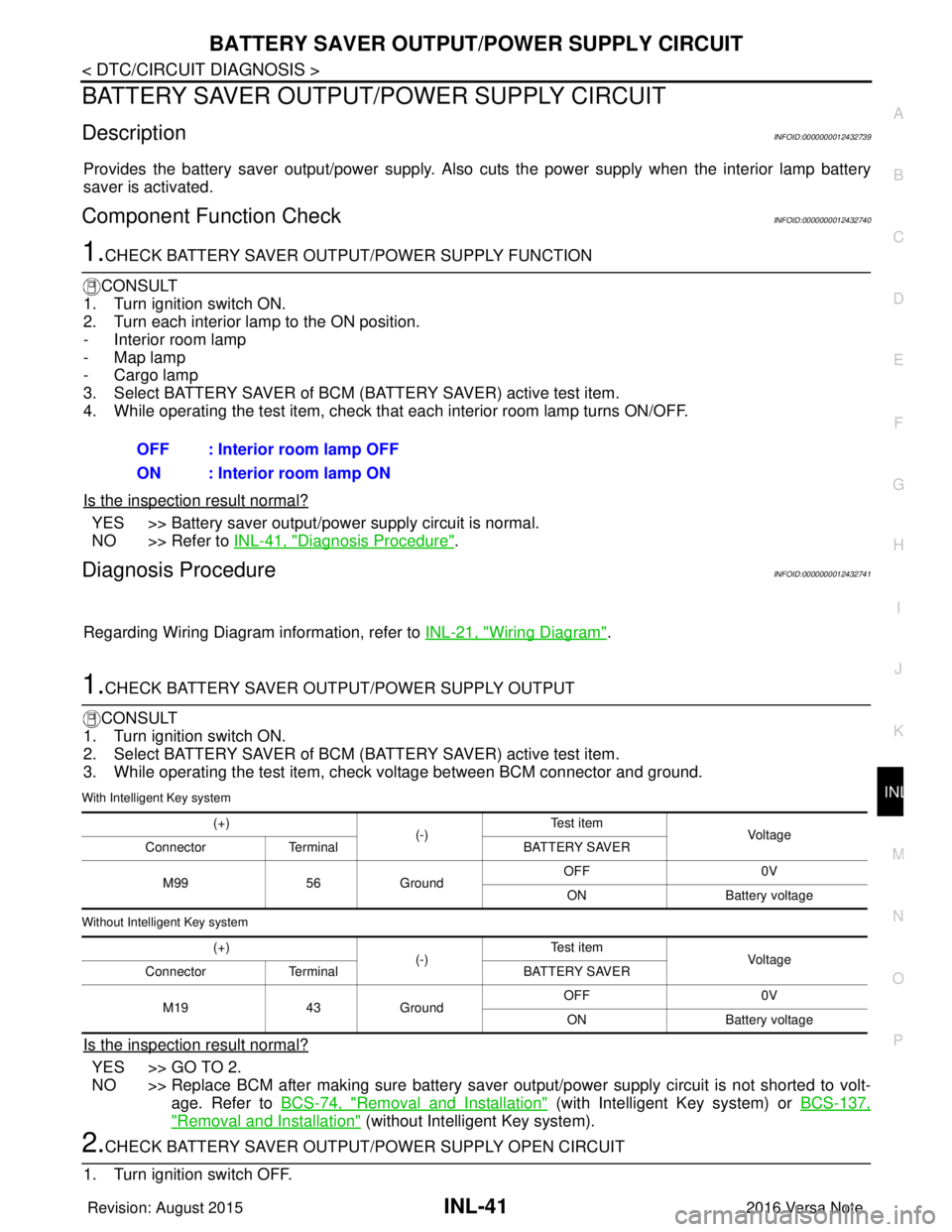
1.CHECK BATTERY SAVER OUTPUT /POWER SUPPLY FUNCTION
CONSULT
1. Turn ignition switch ON.
2. Turn each interior lamp to the ON position.
- Interior room lamp
- Map lamp
- Cargo lamp
3. Select BATTERY SAVER of BCM (BATTERY SAVER) active test item.
4. While operating the test item, check that each interior room lamp turns ON/OFF.
Is the inspection result normal?
YES >> Battery saver output/power supply circuit is normal.
NO >> Refer to INL-41, "
Diagnosis Procedure".
Diagnosis ProcedureINFOID:0000000012432741
Regarding Wiring Diagram information, refer to INL-21, "Wiring Diagram".
1.CHECK BATTERY SAVER OUTPUT/POWER SUPPLY OUTPUT
CONSULT
1. Turn ignition switch ON.
2. Select BATTERY SAVER of BCM (BATTERY SAVER) active test item.
3. While operating the test item, check voltage between BCM connector and ground.
With Intelligent Key system
Without Intelligent Key system
Is the inspection result normal?
YES >> GO TO 2.
NO >> Replace BCM after making sure battery saver out put/power supply circuit is not shorted to volt-
age. Refer to BCS-74, "
Removal and Installation" (with Intelligent Key system) or BCS-137,
"Removal and Installation" (without Intelligent Key system).
2.CHECK BATTERY SAVER OUTPUT/P OWER SUPPLY OPEN CIRCUIT
1. Turn ignition switch OFF. OFF : Interior room lamp OFF
ON : Interior room lamp ON
(+)
(-)Te s t i t e m
Vol tag e
Connector Terminal BATTERY SAVER
M99 56Ground OFF
0V
ON Battery voltage
(+) (-)Te s t i t e m
Vol tag e
Connector Terminal BATTERY SAVER
M19 43Ground OFF
0V
ON Battery voltage
Revision: August 2015 2016 Versa Note
cardiagn.com
Page 2137 of 3641
INTERIOR ROOM LAMP CONTROL CIRCUITINL-43
< DTC/CIRCUIT DIAGNOSIS >
C
DE
F
G H
I
J
K
M A
B
INL
N
O P
INTERIOR ROOM LAMP CONTROL CIRCUIT
DescriptionINFOID:0000000012432742
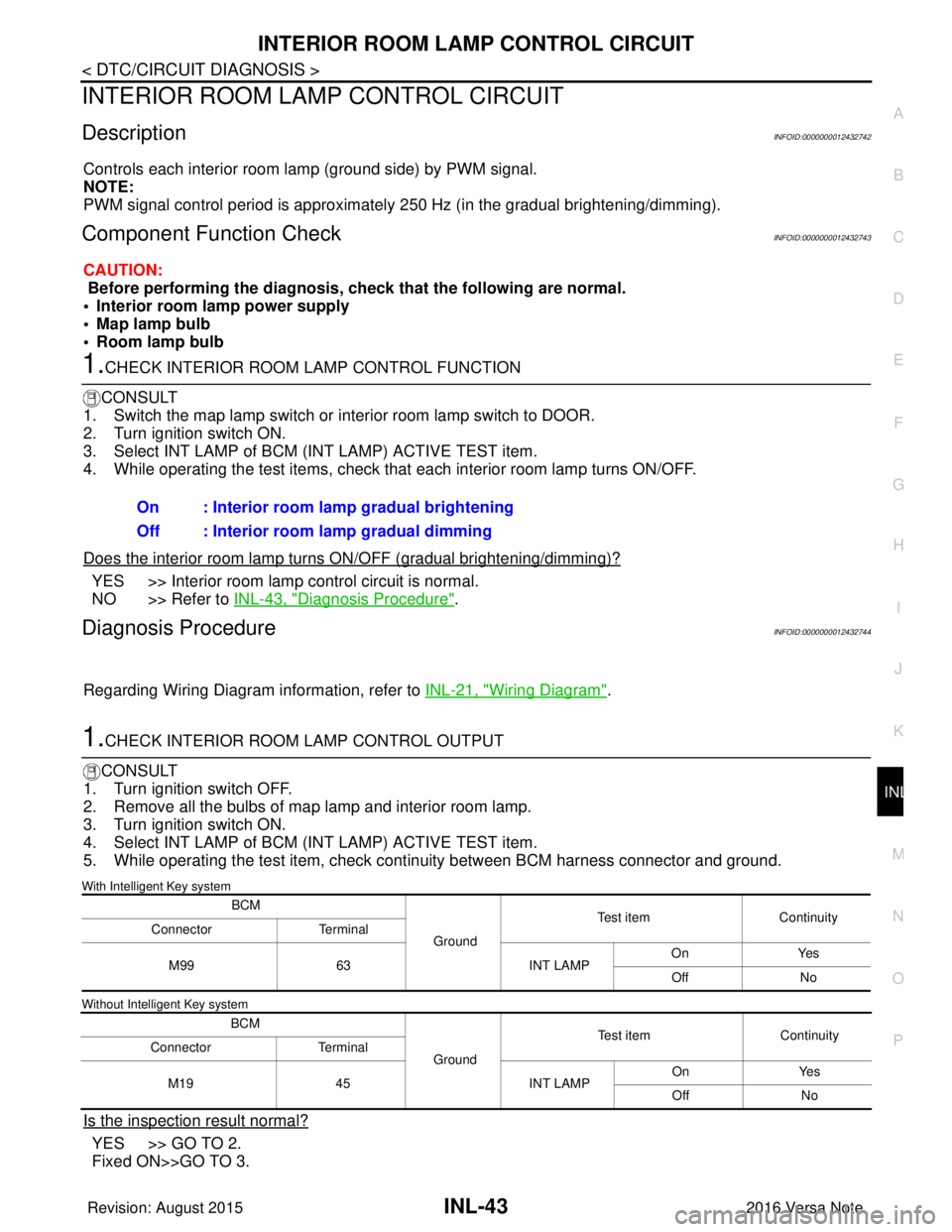
Controls each interior room lamp (ground side) by PWM signal.
NOTE:
PWM signal control period is approximately 250 Hz (in the gradual brightening/dimming).
Component Function CheckINFOID:0000000012432743
CAUTION:
Before performing the diagnosis, check that the following are normal.
• Interior room lamp power supply
• Map lamp bulb
• Room lamp bulb
1.CHECK INTERIOR ROOM LAMP CONTROL FUNCTION
CONSULT
1. Switch the map lamp switch or interior room lamp switch to DOOR.
2. Turn ignition switch ON.
3. Select INT LAMP of BCM (INT LAMP) ACTIVE TEST item.
4. While operating the test items, check that each interior room lamp turns ON/OFF.
Does the interior room lamp turn s ON/OFF (gradual brightening/dimming)?
YES >> Interior room lamp control circuit is normal.
NO >> Refer to INL-43, "
Diagnosis Procedure".
Diagnosis ProcedureINFOID:0000000012432744
Regarding Wiring Diagram information, refer to INL-21, "Wiring Diagram".
1.CHECK INTERIOR ROOM LAMP CONTROL OUTPUT
CONSULT
1. Turn ignition switch OFF.
2. Remove all the bulbs of map lamp and interior room lamp.
3. Turn ignition switch ON.
4. Select INT LAMP of BCM (INT LAMP) ACTIVE TEST item.
5. While operating the test item, check c ontinuity between BCM harness connector and ground.
With Intelligent Key system
Without Intelligent Key system
Is the inspection result normal?
YES >> GO TO 2.
Fixed ON>>GO TO 3.On : Interior room lamp gradual brightening
Off : Interior room lamp gradual dimming
BCM
GroundTest item
Continuity
Connector Terminal
M99 63 INT LAMPOn
Yes
Off No
BCM GroundTest item
Continuity
Connector Terminal
M19 45 INT LAMPOn
Yes
Off No
Revision: August 2015 2016 Versa Note
cardiagn.com
Page 2140 of 3641

INL-46
< DTC/CIRCUIT DIAGNOSIS >
CARGO LAMP CONTROL CIRCUIT
CARGO LAMP CONTROL CIRCUIT
DescriptionINFOID:0000000012432745
Controls the cargo lamp (ground side) to turn the cargo lamp ON and OFF.
Component Function CheckINFOID:0000000012432746
CAUTION:
Before performing the diagnosis, check that the following is normal.
• Battery saver output/power supply
• Cargo lamp bulb
Diagnosis ProcedureINFOID:0000000012432747
Regarding Wiring Diagram information, refer to INL-21, "Wiring Diagram".
1.CHECK CARGO LAMP OUTPUT
1. Turn ignition switch OFF.
2. Remove the cargo lamp bulb.
3. Check continuity between BCM harness connector and ground.
With Intelligent Key system
Without Intelligent Key system
Is the inspection result normal?
YES >> GO TO 2.
Fixed ON>>GO TO 3.
Fixed OFF>>Replace BCM after making sure battery saver output/power supply circuit is not shorted to volt- age. Refer to BCS-74, "
Removal and Installation" (with Intelligent Key system) or BCS-137,
"Removal and Installation" (without Intelligent Key system).
2.CHECK CARGO LAMP OPEN CIRCUIT
Check continuity between BCM harness connector and cargo lamp harness connector.
With Intelligent Key system
Without Intelligent Key system
Is the inspection result normal?
YES >> Replace cargo lamp.
NO >> Repair or replace the harness or connector.
BCM
GroundCondition
Continuity
Connector Terminal
M100 49 Back doorOpen
Yes
Closed No
BCM GroundCondition
Continuity
Connector Terminal
M20 70 Back doorOpen
Yes
Closed No
BCM Cargo lamp
Continuity
Connector TerminalConnector Terminal
M100 49B21 4Yes
BCM Cargo lamp
Continuity
Connector TerminalConnector Terminal
M20 70B21 4Yes
Revision: August 2015 2016 Versa Note
cardiagn.com
Page 2142 of 3641

INL-48
< DTC/CIRCUIT DIAGNOSIS >
PUSH-BUTTON IGNITION SWITCH ILLUMINATION CIRCUIT
PUSH-BUTTON IGNITION SWITCH ILLUMINATION CIRCUIT
DescriptionINFOID:0000000012432748
Provides the power supply and the ground to control the push-button ignition switch illumination.
Component Function CheckINFOID:0000000012432749
1.CHECK PUSH-BUTTON IGNITION SWITCH ILLUMINATION OPERATION
CONSULT
1. Turn the ignition switch ON.
2. Select ENGINE SW ILLUMI of BCM (I NTELLGENT KEY) active test item.
3. While operating the test item, check that the push-button ignition switch illumination turns ON/OFF
Is the inspection result normal?
YES >> Push-button ignition switch illumination circuit is normal.
NO >> Refer to INL-48, "
Diagnosis Procedure".
Diagnosis ProcedureINFOID:0000000012432750
Regarding Wiring Diagram information, refer to INL-28, "Wiring Diagram".
1.CHECK PUSH-BUTTON IGNITION SWITCH ILLUMINATION OPERATION
CONSULT
1. Turn the ignition switch ON.
2. Select ENGINE SW ILLUMI of BCM (INTELLIGENT KEY) active test item.
3. While operating the test item, check voltage bet ween push-button ignition switch connector and ground.
Is the inspection result normal?
YES >> GO TO 4.
NO >> GO TO 2.
2.CHECK PUSH-BUTTON IGNITION SWITCH ILLUMINATION POWER SUPPLY OPEN CIRCUIT
1. Turn the ignition switch OFF.
2. Disconnect BCM connector and push-button ignition switch connector.
3. Check continuity between BCM connector and push-button ignition switch connector.
Is the inspection result normal?
YES >> GO TO 3.
NO >> Repair or replace the harness or connectors. ON : Push-button ignition switch illumination ON
OFF : Push-button ignition
switch illumination OFF
Te r m i n a l s
Te s t i t e m
Vo l ta g e
(+)
(-)
Push-button ignition switch
GroundENGINE SW ILLUMI
Connector Terminal
M25 5 ON
Battery voltage
OFF 0 V
BCM Push-button ignition switch
Continuity
Connector TerminalConnector Terminal
M 989 0M 25 5 Y es
Revision: August 2015 2016 Versa Note
cardiagn.com
Page 2154 of 3641

PRECAUTIONSINT-3
< PRECAUTION >
C
DE
F
G H
I
K L
M A
B
INT
N
O P
PRECAUTION
PRECAUTIONS
Precaution for Supplemental Restraint System (SRS) "AIR BAG" and "SEAT BELT
PRE-TENSIONER"
INFOID:0000000012431852
The Supplemental Restraint System such as “AIR BAG” and “SEAT BELT PRE-TENSIONER”, used along
with a front seat belt, helps to reduce the risk or severi ty of injury to the driver and front passenger for certain
types of collision. Information necessary to service the system safely is included in the SR and SB section of
this Service Manual.
WARNING:
• To avoid rendering the SRS inoper ative, which could increase the risk of personal injury or death in
the event of a collision which would result in air bag inflation, all maintenance must be performed by
an authorized NISSAN/INFINITI dealer.
• Improper maintenance, including in correct removal and installation of the SRS, can lead to personal
injury caused by unintentional act ivation of the system. For removal of Spiral Cable and Air Bag
Module, see the SR section.
• Do not use electrical test equipm ent on any circuit related to the SRS unless instructed to in this
Service Manual. SRS wiring harnesses can be identi fied by yellow and/or orange harnesses or har-
ness connectors.
PRECAUTIONS WHEN USING POWER TOOLS (AIR OR ELECTRIC) AND HAMMERS
WARNING:
• When working near the Airbag Diagnosis Sensor Un it or other Airbag System sensors with the Igni-
tion ON or engine running, DO NOT use air or el ectric power tools or strike near the sensor(s) with a
hammer. Heavy vibration could activate the sensor( s) and deploy the air bag(s), possibly causing
serious injury.
• When using air or electric power tools or hammers, always switch the Ignition OFF, disconnect the
battery and wait at least three mi nutes before performing any service.
Precaution for WorkINFOID:0000000012431853
• When removing or disassembling each component, be ca reful not to damage or deform it. If a component
may be subject to interference, be sure to protect it with a shop cloth.
• When removing (disengaging) components with a screwdriver or similar tool, be sure to wrap the component with a shop cloth or vinyl tape to protect it.
• Protect the removed parts with a shop cloth and prevent them from being dropped.
• Replace a deformed or damaged clip.
• If a part is specified as a non-reusabl e part, always replace it with a new one.
• Be sure to tighten bolts and nuts securely to the specified torque.
• After installation is complete, be sure to check that each part works properly.
• Follow the steps below to clean components:
- Water soluble dirt:
• Dip a soft cloth into lukewarm water, wring the water out of the cloth and wipe the dirty area.
• Then rub with a soft, dry cloth.
-Oily dirt:
• Dip a soft cloth into lukewarm water with mild detergent (concentration: within 2 to 3%) and wipe the dirty
area.
• Then dip a cloth into fresh water, wring the water out of the cloth and wipe the detergent off.
• Then rub with a soft, dry cloth.
- Do not use organic solvent such as thinner, benzene, alcohol or gasoline.
- For genuine leather seats, use a genuine leather seat cleaner.
Revision: August 2015 2016 Versa Note
cardiagn.com