2016 NISSAN NOTE turn signal
[x] Cancel search: turn signalPage 1767 of 3641

SERVICE DATA AND SPECIFICATIONS (SDS)EXL-115
< SERVICE DATA AND SPECIFICATIONS (SDS)
C
DE
F
G H
I
J
K
M A
B
EXL
N
O P
SERVICE DATA AND SPECIFICATIONS (SDS)
SERVICE DATA AND SPECIFICATIONS (SDS)
Bulb specificationINFOID:0000000012432857
*: Always check with the Parts Department for the latest parts info.
Item Wattage (W)*
Front combination Headlamp (HI/LO)
65/55
Front Turn signal/Parking lamp 28/8
Side marker lamp 5
Fog lamp (if equipped) 55
Door mirror turn signal lamp (if equipped) LED
Rear combination Stop/Tail lamp
21/5
Rear turn signal lamp 21
Back-up lamp 21
License plate lamp 5
High-mounted stop lamp LED
Revision: August 20152016 Versa Note
cardiagn.com
Page 1778 of 3641

SYSTEMEXT-11
< SYSTEM DESCRIPTION >
C
DE
F
G H
I
J
L
M A
B
EXT
N
O P
SYSTEM
ACTIVE GRILLE SHUTTER SYSTEM
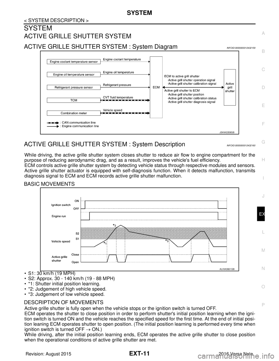
ACTIVE GRILLE SHUTTER SYSTEM : System DiagramINFOID:0000000012432159
ACTIVE GRILLE SHUTTER SYSTEM : System DescriptionINFOID:0000000012432160
While driving, the active grille shutter system closes shutter to reduce air flow to engine compartment for the
purpose of reducing aerodynamic drag, and as a resu lt, improves the vehicle's fuel efficiency.
ECM controls active grille shutter system by detecting vehicle status through respective modules and sensors.
Active grille shutter actuator is equipped with self-d iagnosis function. When it detects malfunction, transmits
diagnosis signal to ECM and ECM records active grille shutter malfunction.
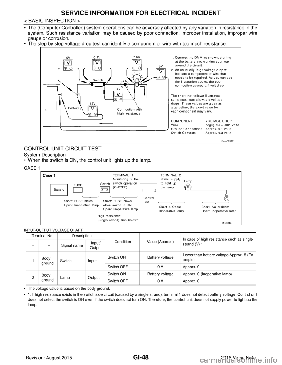
BASIC MOVEMENTS
• S1: 30 km/h (19 MPH)
• S2: Approx. 30 - 140 km/h (19 - 88 MPH)
• *1: Shutter initial position learning.
• *2: Judgement of high vehicle speed.
• *3: Judgement of low vehicle speed.
DESCRIPTION OF MOVEMENTS
Active grille shutter is fully open when the vehicl e stops or the ignition switch is turned OFF.
ECM operates the shutter to close position in order to perform shutter's initial position learning when the igni-
tion switch is turned ON and the vehicle reaches the specified speed for the first time. At the end of initial posi-
tion leaning ECM operates shutter to open position. (The in itial position learning is performed every time when
ignition switch is turned OFF → ON.)
While driving, after the initial position learning ends, EC M operates the active grille shutter to close position
when the operational conditions of active grille shutter are met.
JSKIA3359GB
ALKIA3661GB
Revision: August 2015 2016 Versa Note
cardiagn.com
Page 1936 of 3641

GI-48
< BASIC INSPECTION >
SERVICE INFORMATION FOR ELECTRICAL INCIDENT
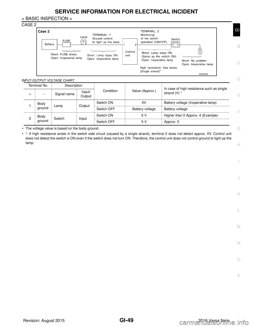
• The (Computer Controlled) system operations can be adversely affected by any variation in resistance in the
system. Such resistance variation may be caused by poor connection, improper installation, improper wire
gauge or corrosion.
• The step by step voltage drop test can identify a component or wire with too much resistance.
CONTROL UNIT CIRCUIT TEST
System Description
• When the switch is ON, the control unit lights up the lamp.
CASE 1
INPUT-OUTPUT VOLTAGE CHART
• The voltage value is based on the body ground.
• *: If high resistance exists in the switch side circuit (caused by a single strand), terminal 1 does not detect battery voltag e. Control unit
does not detect the switch is ON even if the switch does not turn ON. Therefore, the control unit does not supply power to ligh t up the
lamp.
SAIA0258E
Terminal No. Description
Condition Value (Approx.)In case of high resistance such as single
strand (V) *
+ −Signal name Input/
Output
1 Body
ground Switch Input Switch ON
Battery voltageLower than battery voltage Approx. 8 (Ex-
ample)
Switch OFF 0 V Approx. 0
2 Body
ground
Lamp Output Switch ON
Battery voltage Approx. 0 (Inoperative lamp)
Switch OFF 0 V Approx. 0
MGI034A
Revision: August 2015 2016 Versa Note
cardiagn.com
Page 1937 of 3641

SERVICE INFORMATION FOR ELECTRICAL INCIDENTGI-49
< BASIC INSPECTION >
C
DE
F
G H
I
J
K L
M B
GI
N
O P
CASE 2
INPUT-OUTPUT VOLTAGE CHART
• The voltage value is based on the body ground.
• *: If high resistance exists in the switch side circuit (caused by a single strand), terminal 2 does not detect approx. 0V. Co
ntrol unit
does not detect the switch is ON even if the switch does not turn ON. Therefore, the control unit does not control ground to li ght up the
lamp. Terminal No. Description
Condition Value (Approx.)In case of high resistance such as single
strand (V) *
+ −Signal name Input/
Output
1 Body
ground
Lamp Output Switch ON
0VBattery voltage (Inoperative lamp)
Switch OFF Battery voltage Battery voltage
2 Body
ground
Switch Input Switch ON
0 V Higher than 0 Approx. 4 (Example)
Switch OFF 5 V Approx. 5
MGI035A
Revision: August 2015 2016 Versa Note
cardiagn.com
Page 1980 of 3641
![NISSAN NOTE 2016 Service Repair Manual HAC-12
< SYSTEM DESCRIPTION >[MANUAL AIR CONDITIONING]
SYSTEM
Functional Initial Inspection Chart
×
: Applicable
DESCRIPTION
• When A/C switch signal is received from front air control, the thermo NISSAN NOTE 2016 Service Repair Manual HAC-12
< SYSTEM DESCRIPTION >[MANUAL AIR CONDITIONING]
SYSTEM
Functional Initial Inspection Chart
×
: Applicable
DESCRIPTION
• When A/C switch signal is received from front air control, the thermo](/manual-img/5/57363/w960_57363-1979.png)
HAC-12
< SYSTEM DESCRIPTION >[MANUAL AIR CONDITIONING]
SYSTEM
Functional Initial Inspection Chart
×
: Applicable
DESCRIPTION
• When A/C switch signal is received from front air control, the thermo control amp. transmits A/C ON signal to
the BCM according to evaporator fin temperature.
• When the front blower motor is operated, the front air control transmits blower fan ON signal to the BCM.
• BCM transmits the A/C ON signal and blower fan ON signal to ECM via CAN communication line. Refer to LAN-25, "
CAN COMMUNICATION SYSTE M : System Description"
• ECM judges the conditions of each sensor (Refrigerant pressure sensor signal, accelerator position signal,
etc.), and transmits the A/C compressor request signal to IPDM E/R via CAN communication line.
• By receiving the A/C compressor request signal from EC M, IPDM E/R turns the A/C relay to ON, and acti-
vates the compressor. Refer to PCS-5, "
RELAY CONTROL SYSTEM : System Description".
CONTROL BY THERMO CONTROL AMP.
L (1) : Fan ON signal CAN (1) : A/C ON signal
L (2) : A/C switch signal : Blower fan ON signal
L (3) : Defroster position switch 2 CAN (2) : A/C compressor request signal
L (4) : Thermo control amp. ON signal : A/C compressor feedback signal
JPIIA1661GB
Control unitDiagnosis item Location
ABCDE
BCM “BCM-AIR COND” Self-diagnosis
—×———
Data monitor ×————
ECM “ENGINE” Self-diagnosis
(CAN communication line)
———
×—
Data monitor —×× ——
IPDM E/R “IPDM E/R” Self-diagnosis
(CAN communication line)
————
×
Data monitor — — — ×—
Auto active test — — — —×
Revision: August 2015 2016 Versa Note
cardiagn.com
Page 1981 of 3641
![NISSAN NOTE 2016 Service Repair Manual SYSTEMHAC-13
< SYSTEM DESCRIPTION > [MANUAL AIR CONDITIONING]
C
D
E
F
G H
J
K L
M A
B
HAC
N
O P
Low Temperature Protection Control
• When thermo control amp. detects
that evaporator fin temperature NISSAN NOTE 2016 Service Repair Manual SYSTEMHAC-13
< SYSTEM DESCRIPTION > [MANUAL AIR CONDITIONING]
C
D
E
F
G H
J
K L
M A
B
HAC
N
O P
Low Temperature Protection Control
• When thermo control amp. detects
that evaporator fin temperature](/manual-img/5/57363/w960_57363-1980.png)
SYSTEMHAC-13
< SYSTEM DESCRIPTION > [MANUAL AIR CONDITIONING]
C
D
E
F
G H
J
K L
M A
B
HAC
N
O P
Low Temperature Protection Control
• When thermo control amp. detects
that evaporator fin temperature
is 1.5° C (35° F) or less, thermo control amp. switches A/C ON sig-
nal to OFF and stops the compressor.
When the evaporator fin temperature returns to 3 °C (37° F) or
more, the compressor is activated.
CONTROL BY ECM
Refrigerant Pressure Protection
The refrigerant system is protected against excessively high- or low-pressures by the refrigerant pressure s\
en-
sor, located on the liquid tank on the condenser. The refr igerant pressure sensor detects the pressure inside
the refrigerant line and sends a voltage signal to the ECM. If the system pressure rises above or falls below
the following values, the ECM requests the IPDM E/ R to de-energize the A/C relay and disengage the com-
pressor.
• 3.12 MPa (31.82 kg/cm
2, 452.4 psi) or more (When the engine speed is less than 1,500 rpm)
• 2.74 MPa (27.95 kg/cm
2, 397.3 psi) or more (When the engine speed is 1,500 rpm or more)
• 0.14 MPa (1.43 kg/cm
2, 20.3 psi) or less
Compressor Oil Cir culation Control
When the engine starts while the engine coolant temperature is 56 °C (133° F) or less, ECM activates the com-
pressor for approximately 6 seconds and circulates the compressor oil once.
Air Conditioning Cut Control
When the engine is under a high load condition, the ECM transmits an A/C relay OFF request to IPDM E/R,
and stops the compressor. Refer to EC-37, "
AIR CONDITIONING CUT CONTROL : System Description".
Door ControlINFOID:0000000012430719
SWITCHES AND THEIR CONTROL FUNCTIONS
JMIIA1228GB
Revision: August 2015 2016 Versa Note
cardiagn.com
Page 1985 of 3641
![NISSAN NOTE 2016 Service Repair Manual DIAGNOSIS SYSTEM (BCM) (WITH INTELLIGENT KEY SYSTEM)
HAC-17
< SYSTEM DESCRIPTION > [MANUAL AIR CONDITIONING]
C
D
E
F
G H
J
K L
M A
B
HAC
N
O P
DIAGNOSIS SYSTEM (BCM) (WIT H INTELLIGENT KEY SYSTEM)
COM NISSAN NOTE 2016 Service Repair Manual DIAGNOSIS SYSTEM (BCM) (WITH INTELLIGENT KEY SYSTEM)
HAC-17
< SYSTEM DESCRIPTION > [MANUAL AIR CONDITIONING]
C
D
E
F
G H
J
K L
M A
B
HAC
N
O P
DIAGNOSIS SYSTEM (BCM) (WIT H INTELLIGENT KEY SYSTEM)
COM](/manual-img/5/57363/w960_57363-1984.png)
DIAGNOSIS SYSTEM (BCM) (WITH INTELLIGENT KEY SYSTEM)
HAC-17
< SYSTEM DESCRIPTION > [MANUAL AIR CONDITIONING]
C
D
E
F
G H
J
K L
M A
B
HAC
N
O P
DIAGNOSIS SYSTEM (BCM) (WIT H INTELLIGENT KEY SYSTEM)
COMMON ITEM
COMMON ITEM : CONSULT Function (BCM - COMMON ITEM)INFOID:0000000012542299
APPLICATION ITEM
CONSULT performs the following functions via CAN communication with BCM.
SYSTEM APPLICATION
BCM can perform the following functions.
Direct Diagnostic Mode Description
ECU Identification The BCM part number is displayed.
Self Diagnostic Result The BCM self diagnostic results are displayed.
Data Monitor The BCM input/output data is displayed in real time.
Active Test The BCM activates outputs to test components.
Work support The settings for BCM functions can be changed.
Configuration • The vehicle specification can be read and saved.
• The vehicle specification can be written when replacing BCM.
CAN DIAG SUPPORT MNTR The result of transmit/receive diagnosis of CAN communication is displayed.
System Sub System Direct Diagnostic Mode
ECU Identification
Self Diagnostic Result
Data Monitor
Active Test
Work support
Configuration
CAN DIAG SUPPORT MNTR
Door lock
DOOR LOCK ×××
Rear window defogger REAR DEFOGGER ××
Warning chime BUZZER ××
Interior room lamp timer INT LAMP ×××
Exterior lamp HEAD LAMP ×××
Wiper and washer WIPER ×××
Turn signal and hazard warning lamps FLASHER ×××
Air conditioner AIR CONDITIONER ×
Intelligent Key system INTELLIGENT KEY ××××
Combination switch COMB SW ×
BCM BCM× × ×××
Immobilizer IMMU ××××
Interior room lamp battery saver BATTERY SAVER ×××
Vehicle security system THEFT ALM ××
RAP system RETAINED PWR ×
Signal buffer system SIGNAL BUFFER ×
TPMS AIR PRESSURE MONITOR ××××
Panic alarm system PANIC ALARM ×
Revision: August 2015 2016 Versa Note
cardiagn.com
Page 1987 of 3641
![NISSAN NOTE 2016 Service Repair Manual DIAGNOSIS SYSTEM (BCM) (WITHOUT INTELLIGENT KEY SYSTEM)HAC-19
< SYSTEM DESCRIPTION > [MANUAL AIR CONDITIONING]
C
D
E
F
G H
J
K L
M A
B
HAC
N
O P
DIAGNOSIS SYSTEM (BCM) (WITHO UT INTELLIGENT KEY SYSTEM NISSAN NOTE 2016 Service Repair Manual DIAGNOSIS SYSTEM (BCM) (WITHOUT INTELLIGENT KEY SYSTEM)HAC-19
< SYSTEM DESCRIPTION > [MANUAL AIR CONDITIONING]
C
D
E
F
G H
J
K L
M A
B
HAC
N
O P
DIAGNOSIS SYSTEM (BCM) (WITHO UT INTELLIGENT KEY SYSTEM](/manual-img/5/57363/w960_57363-1986.png)
DIAGNOSIS SYSTEM (BCM) (WITHOUT INTELLIGENT KEY SYSTEM)HAC-19
< SYSTEM DESCRIPTION > [MANUAL AIR CONDITIONING]
C
D
E
F
G H
J
K L
M A
B
HAC
N
O P
DIAGNOSIS SYSTEM (BCM) (WITHO UT INTELLIGENT KEY SYSTEM)
COMMON ITEM
COMMON ITEM : CONSULT Function (BCM - COMMON ITEM)INFOID:0000000012542301
APPLICATION ITEM
CONSULT performs the following functions via CAN communication with BCM.
SYSTEM APPLICATION
BCM can perform the following functions.
Direct Diagnostic Mode Description
ECU Identification The BCM part number is displayed.
Self Diagnostic Result The BCM self diagnostic results are displayed.
Data Monitor The BCM input/output data is displayed in real time.
Active Test The BCM activates outputs to test components.
Work support The settings for BCM functions can be changed.
Configuration • The vehicle specification can be read and saved.
• The vehicle specification can be written when replacing BCM.
CAN DIAG SUPPORT MNTR The result of transmit/receive diagnosis of CAN communication is displayed.
System Sub System Direct Diagnostic Mode
ECU Identification
Self Diagnostic Result
Data Monitor
Active Test
Work support
Configuration
CAN DIAG SUPPORT MNTR
Door lock
DOOR LOCK ×××
Rear window defogger REAR DEFOGGER ××
Warning chime BUZZER ××
Interior room lamp timer INT LAMP ×××
Remote keyless entry system MULTI REMOTE ENT ×××
Exterior lamp HEAD LAMP ×××
Wiper and washer WIPER ×××
Turn signal and hazard warning lamps FLASHER ××
Air conditioner AIR CONDITIONER ×
Combination switch COMB SW ×
BCM BCM× × ×××
Immobilizer IMMU ×××
Interior room lamp battery saver BATTERY SAVER ×××
Vehicle security system THEFT ALM ××
RAP system RETAINED PWR ××
Signal buffer system SIGNAL BUFFER ×
TPMS AIR PRESSURE MONITOR ××××
Panic alarm system PANIC ALARM ×
Revision: August 2015 2016 Versa Note
cardiagn.com