2016 NISSAN NOTE parking brake
[x] Cancel search: parking brakePage 2341 of 3641
MA-26
< PERIODIC MAINTENANCE >
CHASSIS AND BODY MAINTENANCE
CHASSIS AND BODY MAINTENANCE
EXHAUST SYSTEM
EXHAUST SYSTEM : InspectionINFOID:0000000012432266
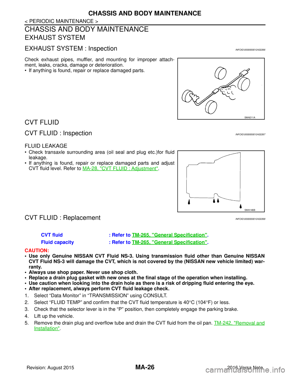
Check exhaust pipes, muffler, and mounting for improper attach-
ment, leaks, cracks, damage or deterioration.
• If anything is found, repair or replace damaged parts.
CVT FLUID
CVT FLUID : InspectionINFOID:0000000012432267
FLUID LEAKAGE
• Check transaxle surrounding area (oil seal and plug etc.)for fluidleakage.
• If anything is found, repair or replace damaged parts and adjust CVT fluid level. Refer to MA-28, "
CVT FLUID : Adjustment".
CVT FLUID : ReplacementINFOID:0000000012432268
CAUTION:
• Use only Genuine NISSAN CVT Fluid NS-3. Using transmission fluid other than Genuine NISSAN
CVT Fluid NS-3 will damage the CVT, which is not covered by the (NISSAN new vehicle limited) war-
ranty.
• Always use shop paper. Never use shop cloth.
• Replace a drain plug gasket with new ones at the final stage of the operation when installing.
• Use caution when looking into the drain hole as th ere is a risk of dripping fluid entering the eye.
• After replacement, always perform CVT fluid leakage check.
1. Select “Data Monitor” in “T RANSMISSION” using CONSULT.
2. Select “FLUID TEMP” and confirm t hat the CVT fluid temperature is 40°C (104° F) or less.
3. Check that the selector lever is in the “P ” position, then completely engage the parking brake.
4. Lift up the vehicle.
5. Remove the drain plug and overflow tube and drain the CVT fluid from the oil pan. TM-242, "
Removal and
Installation".
SMA211A
SMA146B
CVT fluid: Refer to TM-265, "General Specification".
Fluid capacity : Refer to TM-265, "
General Specification".
Revision: August 2015 2016 Versa Note
cardiagn.com
Page 2343 of 3641
MA-28
< PERIODIC MAINTENANCE >
CHASSIS AND BODY MAINTENANCE
29. When the flow of CVT fluid slows to a drip, tighten the drain plug to the specified torque. TM-242,
"Removal and Installation".
CAUTION:
Never reuse drain plug gasket.
30. Lift down the vehicle.
31. Select “Work Support” in “TRANSMISSION” using CONSULT.
32. Select “CONFORM CVTF DETERIORTN”.
33. Select “Erase”.
34. Stop the engine.
CVT FLUID : AdjustmentINFOID:0000000012432269
CAUTION:
• Use only Genuine NISSAN CVT Fluid NS-3. Using transmission fluid other than Genuine NISSAN
CVT Fluid NS-3 will damage the CVT, which is not covered by the (NISSAN new vehicle limited) war-
ranty.
• During adjustment of the CVT fluid level, check CO NSULT so that the oil temperature may be main-
tained from 35 to 45 °C (95 to 113 °F).
• Use caution when looking into the drain hole as th ere is a risk of dripping fluid entering the eye.
1. Check that the selector lever is in the “P ” position, then completely engage the parking brake.
2. Start the engine.
3. Adjust the CVT fluid temperature to be approximately 40 °C (104° F).
NOTE:
The CVT fluid is largely affected by temperature. Therefore be sure to use CONSULT and check the
“FLUID TEMP” under “TRANSMISSION” in “Data Monitor” while adjusting.
4. While depressing the brake pedal, shift the selector lever to the entire position from “P” to “L”, and shift it to the “P” position.
NOTE:
Hold the lever at each position for 5 seconds.
5. Lift up the vehicle.
6. Check that there is no CVT fluid leakage.
7. Remove the drain plug. Refer to TM-242, "
Removal and Installation".
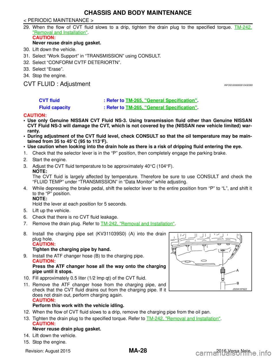
8. Install the charging pipe set (KV311039S0) (A) into the drain plug hole.
CAUTION:
Tighten the charging pipe by hand.
9. Install the ATF changer hose (B) to the charging pipe. CAUTION:
Press the ATF changer hose all the way onto the charging
pipe until it stops.
10. Fill approximately 0.5 liter (1/2 lmp qt) of the CVT fluid.
11. Remove the ATF changer hose from the charging pipe, and check that the CVT fluid drains out from the charging pipe. If it
does not drain out, perform charging again.
CAUTION:
Perform this work with the vehicle idling.
12. When the flow of CVT fluid slows to a drip, remove the charging pipe from the oil pan.
13. Tighten the drain plug to the specified torque. Refer to TM-242, "
Removal and Installation".
CAUTION:
Never reuse drain plug gasket.
14. Lift down the vehicle.
15. Stop the engine. CVT fluid
: Refer to TM-265, "
General Specification".
Fluid capacity : Refer to TM-265, "
General Specification".
JSDIA1876ZZ
Revision: August 2015 2016 Versa Note
cardiagn.com
Page 2349 of 3641
MA-34
< PERIODIC MAINTENANCE >
CHASSIS AND BODY MAINTENANCE
TIRE ROTATION
• Follow the maintenance schedule for tire rotation service intervals.Refer to MA-7, "
Introduction of Periodic Maintenance".
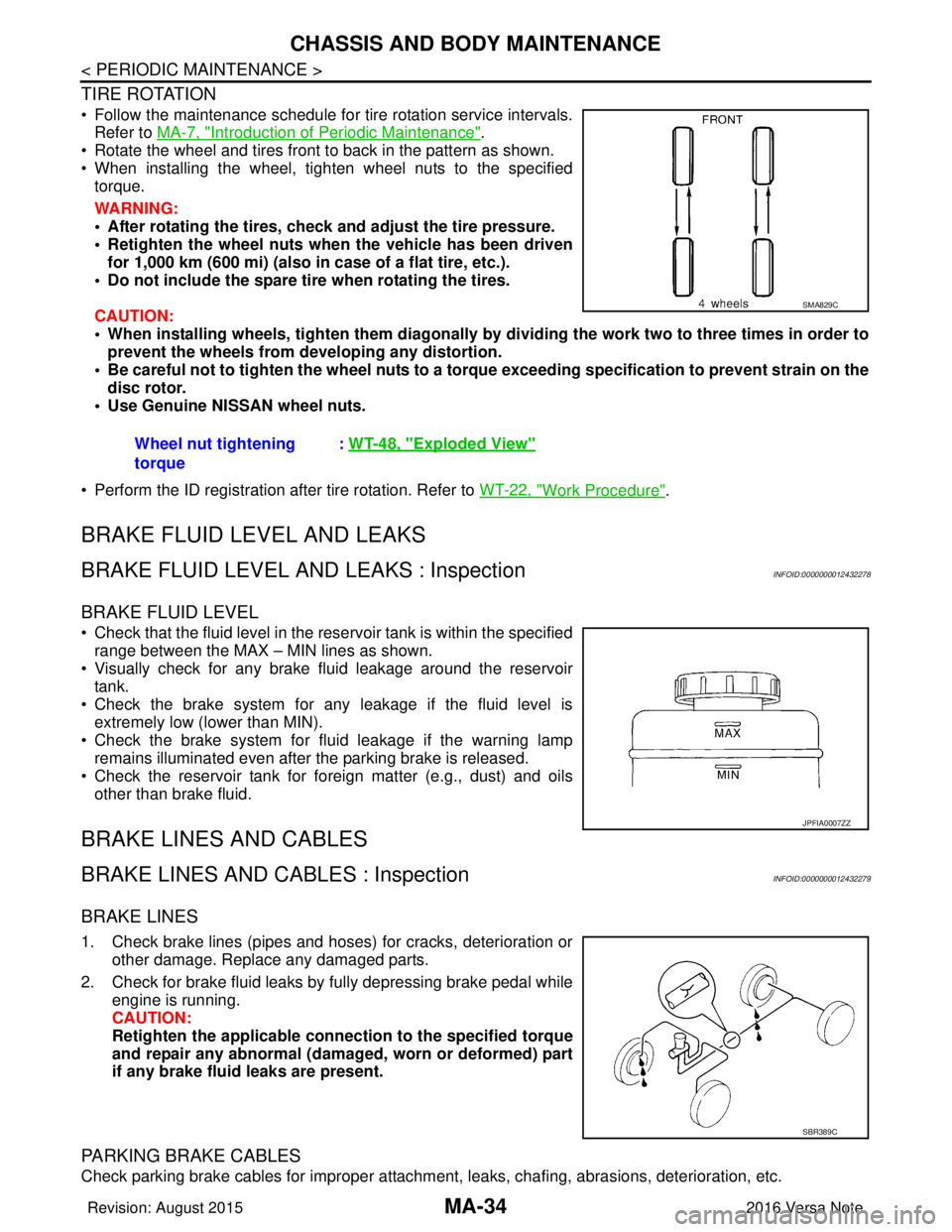
• Rotate the wheel and tires front to back in the pattern as shown.
• When installing the wheel, tighten wheel nuts to the specified torque.
WARNING:
• After rotating the tires, check and adjust the tire pressure.
• Retighten the wheel nuts when the vehicle has been driven
for 1,000 km (600 mi) (also in case of a flat tire, etc.).
• Do not include the spare tire when rotating the tires.
CAUTION:
• When installing wheels, ti ghten them diagonally by dividing the work two to three times in order to
prevent the wheels from d eveloping any distortion.
• Be careful not to tighten the wh eel nuts to a torque exceeding speci fication to prevent strain on the
disc rotor.
• Use Genuine NISSAN wheel nuts.
• Perform the ID registration after tire rotation. Refer to WT-22, "
Work Procedure".
BRAKE FLUID LEVEL AND LEAKS
BRAKE FLUID LEVEL AND LEAKS : InspectionINFOID:0000000012432278
BRAKE FLUID LEVEL
• Check that the fluid level in the reservoir tank is within the specified
range between the MAX – MIN lines as shown.
• Visually check for any brake fluid leakage around the reservoir tank.
• Check the brake system for any leakage if the fluid level is extremely low (lower than MIN).
• Check the brake system for fluid leakage if the warning lamp
remains illuminated even after the parking brake is released.
• Check the reservoir tank for foreign matter (e.g., dust) and oils other than brake fluid.
BRAKE LINES AND CABLES
BRAKE LINES AND CABLES : InspectionINFOID:0000000012432279
BRAKE LINES
1. Check brake lines (pipes and hoses) for cracks, deterioration or other damage. Replace any damaged parts.
2. Check for brake fluid leaks by fully depressing brake pedal while engine is running.
CAUTION:
Retighten the applicable conn ection to the specified torque
and repair any abnormal (damag ed, worn or deformed) part
if any brake fluid leaks are present.
PARKING BRAKE CABLES
Check parking brake cables for improper attachment , leaks, chafing, abrasions, deterioration, etc.
Wheel nut tightening
torque
:
WT-48, "
Exploded View"
SMA829C
JPFIA0007ZZ
SBR389C
Revision: August 2015 2016 Versa Note
cardiagn.com
Page 2350 of 3641
CHASSIS AND BODY MAINTENANCEMA-35
< PERIODIC MAINTENANCE >
C
DE
F
G H
I
J
K L
M B
MA
N
O A
BRAKE FLUID
BRAKE FLUID : InspectionINFOID:0000000012432280
BRAKE FLUID LEVEL
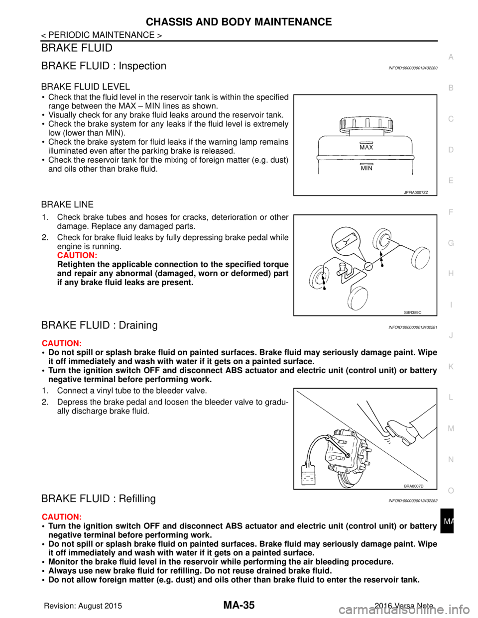
• Check that the fluid level in the re
servoir tank is within the specified
range between the MAX – MIN lines as shown.
• Visually check for any brake fluid leaks around the reservoir tank.
• Check the brake system for any leak s if the fluid level is extremely
low (lower than MIN).
• Check the brake system for fluid leaks if the warning lamp remains
illuminated even after the parking brake is released.
• Check the reservoir tank for the mixing of foreign matter (e.g. dust) and oils other than brake fluid.
BRAKE LINE
1. Check brake tubes and hoses for cracks, deterioration or other
damage. Replace any damaged parts.
2. Check for brake fluid leaks by fully depressing brake pedal while engine is running.
CAUTION:
Retighten the applicable conn ection to the specified torque
and repair any abnormal (damag ed, worn or deformed) part
if any brake fluid leaks are present.
BRAKE FLUID : DrainingINFOID:0000000012432281
CAUTION:
• Do not spill or splash brake fluid on painted su rfaces. Brake fluid may seriously damage paint. Wipe
it off immediately and wash with wa ter if it gets on a painted surface.
• Turn the ignition switch OFF an d disconnect ABS actuator and electric unit (control unit) or battery
negative terminal before performing work.
1. Connect a vinyl tube to the bleeder valve.
2. Depress the brake pedal and loosen the bleeder valve to gradu- ally discharge brake fluid.
BRAKE FLUID : RefillingINFOID:0000000012432282
CAUTION:
• Turn the ignition switch OFF an d disconnect ABS actuator and electric unit (control unit) or battery
negative terminal before performing work.
• Do not spill or splash brake fluid on painted su rfaces. Brake fluid may seriously damage paint. Wipe
it off immediately and wash with wa ter if it gets on a painted surface.
• Monitor the brake fluid level in the reservoir while performing the air bleeding procedure.
• Always use new brake fluid for refillin g. Do not reuse drained brake fluid.
• Do not allow foreign matter (e.g. dust) and oils ot her than brake fluid to enter the reservoir tank.
JPFIA0007ZZ
SBR389C
BRA0007D
Revision: August 2015 2016 Versa Note
cardiagn.com
Page 2353 of 3641
MA-38
< PERIODIC MAINTENANCE >
CHASSIS AND BODY MAINTENANCE
DRUM BRAKE : Inspection
INFOID:0000000012432287
INSPECTION
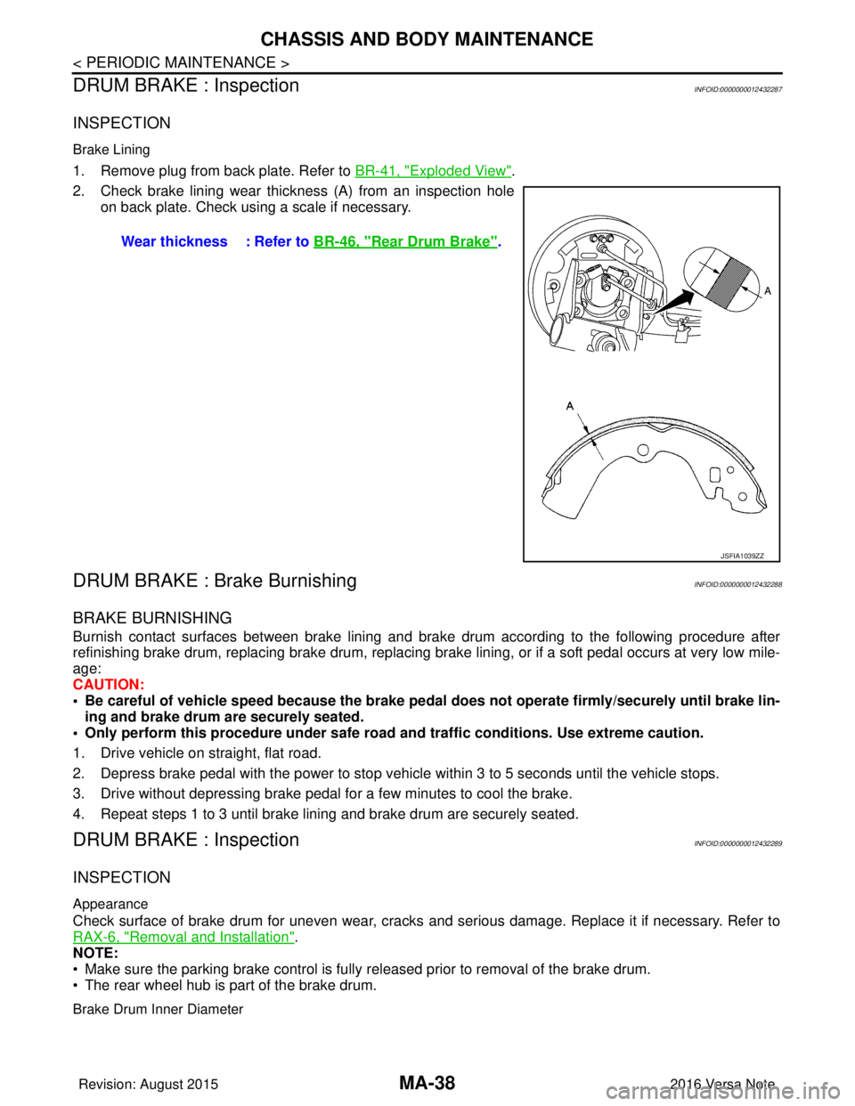
Brake Lining
1. Remove plug from back plate. Refer to BR-41, "Exploded View".
2. Check brake lining wear thickness (A) from an inspection hole on back plate. Check using a scale if necessary.
DRUM BRAKE : Brake BurnishingINFOID:0000000012432288
BRAKE BURNISHING
Burnish contact surfaces between brake lining and brak e drum according to the following procedure after
refinishing brake drum, replacing brake drum, replacing brak e lining, or if a soft pedal occurs at very low mile-
age:
CAUTION:
• Be careful of vehicle speed because the brake peda l does not operate firmly/securely until brake lin-
ing and brake drum are securely seated.
• Only perform this procedure under safe road and traffic conditions. Use extreme caution.
1. Drive vehicle on straight, flat road.
2. Depress brake pedal with the power to stop vehicle within 3 to 5 seconds until the vehicle stops.
3. Drive without depressing brake pedal for a few minutes to cool the brake.
4. Repeat steps 1 to 3 until brake lining and brake drum are securely seated.
DRUM BRAKE : InspectionINFOID:0000000012432289
INSPECTION
Appearance
Check surface of brake drum for uneven wear, cracks and serious damage. Replace it if necessary. Refer to
RAX-6, "
Removal and Installation".
NOTE:
• Make sure the parking brake control is fully released prior to removal of the brake drum.
• The rear wheel hub is part of the brake drum.
Brake Drum Inner Diameter
Wear thickness : Refer to BR-46, "Rear Drum Brake".
JSFIA1039ZZ
Revision: August 2015 2016 Versa Note
cardiagn.com
Page 2360 of 3641

MWI-2
U1010 CONTROL UNIT (CAN) .........................39
Description ........................................................... ...39
DTC Logic ...............................................................39
Diagnosis Procedure ..............................................39
B2205 VEHICLE SPEED ...................................40
Description ........................................................... ...40
DTC Logic ...............................................................40
Diagnosis Procedure .............................................40
B2267 ENGINE SPEED .....................................41
Description ........................................................... ...41
DTC Logic ...............................................................41
Diagnosis Procedure ..............................................41
B2268 WATER TEMP ........................................42
Description ........................................................... ...42
DTC Logic ...............................................................42
Diagnosis Procedure ..............................................42
POWER SUPPLY AND GROUND CIRCUIT .....43
COMBINATION METER ........................................ ...43
COMBINATION METER : Diagnosis Procedure ....43
BCM (BODY CONTROL MODULE) ...................... ...43
BCM (BODY CONTROL MODULE) : Diagnosis
Procedure ...............................................................
44
FUEL LEVEL SENSOR SIGNAL CIRCUIT .......45
Description ........................................................... ...45
Component Function Check ...................................45
Diagnosis Procedure .............................................45
Component Inspection ............................................46
WASHER FLUID LEVEL SWITCH CIRCUIT ....47
Description ........................................................... ...47
Diagnosis Procedure ..............................................47
Component Inspection ............................................47
SYMPTOM DIAGNOSIS .............................48
THE FUEL GAUGE INDICATOR DOES NOT
OPERATE ....................................................... ...
48
Description ........................................................... ...48
Diagnosis Procedure ..............................................48
THE OIL PRESSURE WARNING LAMP
DOES NOT TURN ON .......................................
49
Description ..............................................................49
Diagnosis Procedure ..............................................49
THE OIL PRESSURE WARNING LAMP
DOES NOT TURN OFF .....................................
50
Description ........................................................... ...50
Diagnosis Procedure ..............................................50
THE DOOR OPEN WARNING CONTINUES
DISPLAYING, OR DOES NOT DISPLAY ..........
51
Description ........................................................... ...51
Diagnosis Procedure ..............................................51
THE PARKING BRAKE RELEASE WARNING
CONTINUES DISPLAYING, OR DOES NOT
DISPLAY ............................................................
52
Description ........................................................... ...52
Diagnosis Procedure ...............................................52
THE LOW WASHER FLUID WARNING CON-
TINUES DISPLAYING, or DOES NOT DIS-
PLAY ..................................................................
53
Description ........................................................... ...53
Diagnosis Procedure ...............................................53
REMOVAL AND INSTALLATION ..............54
COMBINATION METER ................................. ...54
Removal and Installation .........................................54
TYPE B
HOW TO USE THIS MANU AL ...................
55
APPLICATION NOTICE ................................. ...55
Information ........................................................... ...55
PRECAUTION ............................................56
PRECAUTIONS .............................................. ...56
Precaution for Supplemental Restraint System
(SRS) "AIR BAG" and "SEAT BELT PRE-TEN-
SIONER" .............................................................. ...
56
PREPARATION ..........................................57
PREPARATION .............................................. ...57
Commercial Service Tools ................................... ...57
SYSTEM DESCRIPTION ...........................58
COMPONENT PARTS .................................... ...58
METER SYSTEM .......................................................58
METER SYSTEM : Component Parts Location ... ...58
METER SYSTEM : Combination Meter ..................59
SYSTEM ............................................................61
METER SYSTEM .......................................................61
METER SYSTEM : System Description ............... ...61
METER SYSTEM : Fail-safe ...................................62
SPEEDOMETER .................................................... ...63
SPEEDOMETER : System Description ..................63
TACHOMETER ....................................................... ...63
TACHOMETER : System Description .....................64
SHIFT POSITION INDICATOR .............................. ...64
SHIFT POSITION INDICATOR : System Descrip-
tion ....................................................................... ...
64
HIGH WATER TEMPERATURE WARNING LAMP ...64
HIGH WATER TEMPERATURE WARNING
LAMP : System Description ....................................
64
Revision: August 2015 2016 Versa Note
cardiagn.com
Page 2361 of 3641

MWI
MWI-3
C
DE
F
G H
I
J
K L
M B
A
O P
OIL PRESSURE WARNING
LAMP ...........................
65
OIL PRESSURE WARNING LAMP : System De-
scription ............................................................... ....
65
METER ILLUMINATION CONTROL ..................... ....65
METER ILLUMINATION CONTROL : System De-
scription ...................................................................
66
INFORMATION DISPLAY ..................................... ....66
INFORMATION DISPLAY : System Description .....66
OPERATION ................................................... ....68
Switch Name and Function ................................. ....68
DIAGNOSIS SYSTEM (COMBINATION
METER) ..............................................................
69
On Board Diagnosis Function ............................. ....69
CONSULT Function (METER/M&A) .......................71
ECU DIAGNOSIS INFORMATION ..............74
COMBINATION METER ................................. ....74
Reference Value ................................................. ....74
Fail-safe ..................................................................77
DTC Index ...............................................................77
BCM (BODY CONTROL MODULE) ...................78
List of ECU Reference ........................................ ....78
WIRING DIAGRAM ......................................79
METER SYSTEM ............................................ ....79
Wiring Diagram ................................................... ....79
BASIC INSPECTION ...................................92
DIAGNOSIS AND REPAIR WORK FLOW .... ....92
Work Flow ........................................................... ....92
DTC/CIRCUIT DIAGNOSIS .........................93
U1000 CAN COMM CI RCUIT .............................93
DTC Logic ........................................................... ....93
Diagnosis Procedure ..............................................93
U1010 CONTROL UNIT (CAN) ..........................94
Description ..............................................................94
DTC Logic ...............................................................94
Diagnosis Procedure ...............................................94
B2205 VEHICLE SPEED ....................................95
Description ..............................................................95
DTC Logic ...............................................................95
Diagnosis Procedure ..............................................95
B2267 ENGINE SPEED .....................................96
Description .......................................................... ....96
DTC Logic ...............................................................96
Diagnosis Procedure ...............................................96
B2268 WATER TEMP ........................................97
Description .......................................................... ....97
DTC Logic ...............................................................97
Diagnosis Procedure ........................................... ....97
POWER SUPPLY AND GROUND CIRCUIT ....98
COMBINATION METER ........................................ ....98
COMBINATION METER : Diagnosis Procedure .....98
BCM (BODY CONTROL SYSTEM) (WITHOUT IN-
TELLIGENT KEY SYSTEM) .................................. ....
98
BCM (BODY CONTROL SYSTEM) (WITHOUT
INTELLIGENT KEY SYSTEM) : Diagnosis Proce-
dure ..................................................................... ....
98
BCM (BODY CONTROL SYSTEM) (WITH INTEL-
LIGENT KEY SYSTEM) .............................................
99
BCM (BODY CONTROL SYSTEM) (WITH INTEL-
LIGENT KEY SYSTEM) : Diagnosis Procedure .. ....
99
FUEL LEVEL SENSOR SIGNAL CIRCUIT ....101
Description .............................................................101
Component Function Check ..................................101
Diagnosis Procedure ............................................101
Component Inspection ...........................................102
STEERING SWITCH .......................................103
Diagnosis Procedure .............................................103
AMBIENT SENSOR SIGNAL CIRCUIT ..........104
Description .............................................................104
Diagnosis Procedure ............................................104
Component Inspection ...........................................105
WASHER FLUID LEVEL SWITCH CIRCUIT ..106
Description .............................................................106
Diagnosis Procedure .............................................106
Component Inspection ...........................................106
SYMPTOM DIAGNOSIS ............................107
THE FUEL GAUGE INDICATOR DOES NOT
OPERATE .......................................................
107
Description ........................................................... ..107
Diagnosis Procedure .............................................107
THE OIL PRESSURE WARNING LAMP
DOES NOT TURN ON .....................................
108
Description .............................................................108
Diagnosis Procedure .............................................108
THE OIL PRESSURE WARNING LAMP
DOES NOT TURN OFF ...................................
109
Description .............................................................109
Diagnosis Procedure .............................................109
THE DOOR OPEN WARNING CONTINUES
DISPLAYING, OR DOES NOT DISPLAY .......
110
Description .............................................................110
Diagnosis Procedure .............................................110
THE PARKING BRAKE RELEASE WARNING
CONTINUES DISPLAYING, OR DOES NOT
DISPLAY .........................................................
111
Revision: August 2015 2016 Versa Note
cardiagn.com
Page 2366 of 3641
![NISSAN NOTE 2016 Service Repair Manual MWI-8
< SYSTEM DESCRIPTION >[TYPE A]
COMPONENT PARTS
SYSTEM DESCRIPTION
COMPONENT PARTS
METER SYSTEM
METER SYSTEM : Component Parts LocationINFOID:0000000012432541
A. Combination meter
B. View with re](/manual-img/5/57363/w960_57363-2365.png "NISSAN NOTE 2016 Service Repair Manual MWI-8
< SYSTEM DESCRIPTION >[TYPE A]
COMPONENT PARTS
SYSTEM DESCRIPTION
COMPONENT PARTS
METER SYSTEM
METER SYSTEM : Component Parts LocationINFOID:0000000012432541
A. Combination meter
B. View with re")
MWI-8
< SYSTEM DESCRIPTION >[TYPE A]
COMPONENT PARTS
SYSTEM DESCRIPTION
COMPONENT PARTS
METER SYSTEM
METER SYSTEM : Component Parts LocationINFOID:0000000012432541
A. Combination meter
B. View with rear lower seat cushion and inspection hole
cover removed.
No. Component Function
1. Parking brake switch Transmits the parking brake switch signal to the combination meter.
2. ABS actuator and electric unit
(control unit) Transmits the vehicle speed signal to the combination meter via CAN communication.
Refer to BRC-7, "
Component Parts Location" for detailed installation location.
3. Washer fluid level switch Transmits the washer fluid level switch signal to the combination meter (for Canada).
Refer to WW-6, "
Component Parts Location" for detailed installation location.
4. Engine oil pressure sensor Transmits the engine oil pressure sensor signal to the ECM.
Refer to EM-93, "
Exploded View" for detailed installation location.
5. TCM Transmits the shift position signal to the combination meter via CAN communication
(with CVT).
Refer to TM-61, "
CVT CONTROL SYSTEM : Co
mponent Parts Location" for detailed
installation location.
AWNIA3135ZZ
Revision: August 2015 2016 Versa Note
cardiagn.com