2016 NISSAN NOTE engine oil
[x] Cancel search: engine oilPage 1018 of 3641
DRIVE BELTEM-17
< PERIODIC MAINTENANCE > [HR16DE]
C
D
E
F
G H
I
J
K L
M A
EM
NP
O
4. Tighten the lock nut to final tightening specification.
5. Check that belt tension is within the specification using suitable tool. Refer to
EM-116, "
Drive Belt".
InspectionINFOID:0000000012431695
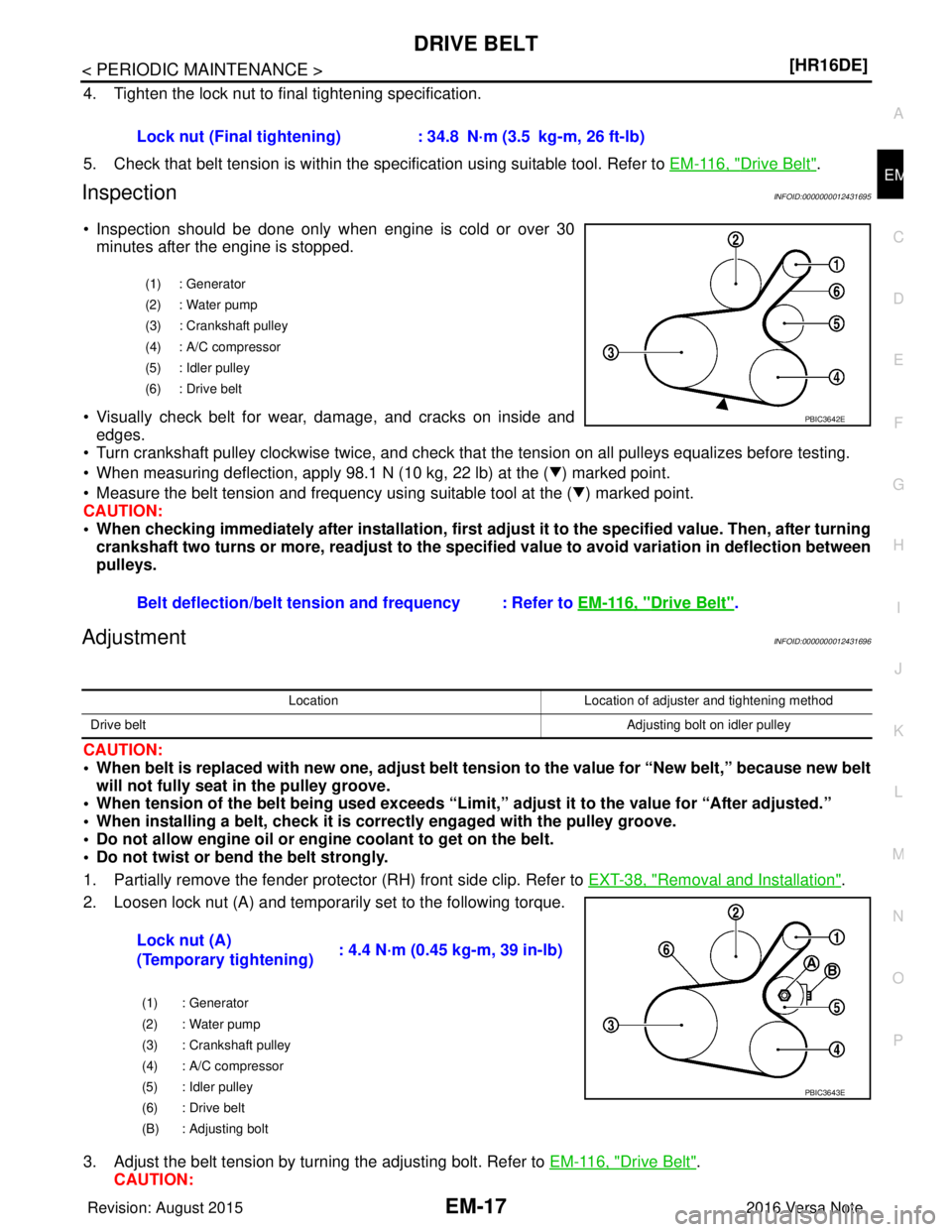
• Inspection should be done only when engine is cold or over 30
minutes after the engine is stopped.
• Visually check belt for wear, damage, and cracks on inside and edges.
• Turn crankshaft pulley clockwise twice, and check that the tension on all pulleys equalizes before testing.
• When measuring deflection, apply 98.1 N (10 kg, 22 lb) at the ( ) marked point.
• Measure the belt tension and frequency using suitable tool at the ( ) marked point.
CAUTION:
• When checking immediately after installation, first ad just it to the specified value. Then, after turning
crankshaft two turns or more, readjust to the specified value to avoid varia tion in deflection between
pulleys.
AdjustmentINFOID:0000000012431696
CAUTION:
• When belt is replaced with new one, adjust belt te nsion to the value for “New belt,” because new belt
will not fully seat in the pulley groove.
• When tension of the belt being used exceeds “Limit,” adjust it to the value for “After adjusted.”
• When installing a belt, check it is correctly engaged with the pulley groove.
• Do not allow engine oil or engine coolant to get on the belt.
• Do not twist or bend the belt strongly.
1. Partially remove the fender protector (RH) front side clip. Refer to EXT-38, "
Removal and Installation".
2. Loosen lock nut (A) and temporarily set to the following torque.
3. Adjust the belt tension by turning the adjusting bolt. Refer to EM-116, "
Drive Belt".
CAUTION: Lock nut (Final tightening) :
34.8 N·m (3.5 kg-m, 26 ft-lb)
(1) : Generator
(2) : Water pump
(3) : Crankshaft pulley
(4) : A/C compressor
(5) : Idler pulley
(6) : Drive belt
Belt deflection/belt tension and frequency : Refer to EM-116, "Drive Belt".
PBIC3642E
LocationLocation of adjuster and tightening method
Drive belt Adjusting bolt on idler pulley
Lock nut (A)
(Temporary tightening): 4.4 N·m (0.45 kg-m, 39 in-lb)
(1) : Generator
(2) : Water pump
(3) : Crankshaft pulley
(4) : A/C compressor
(5) : Idler pulley
(6) : Drive belt
(B) : Adjusting bolt
PBIC3643E
Revision: August 2015
2016 Versa Note
cardiagn.com
Page 1030 of 3641
INTAKE MANIFOLDEM-29
< REMOVAL AND INSTALLATION > [HR16DE]
C
D
E
F
G H
I
J
K L
M A
EM
NP
O
Handle EVAP canister purge volume control
solenoid valve carefully and avoid impacts.
5. Disconnect vacuum hose for brake booster from intake manifold.
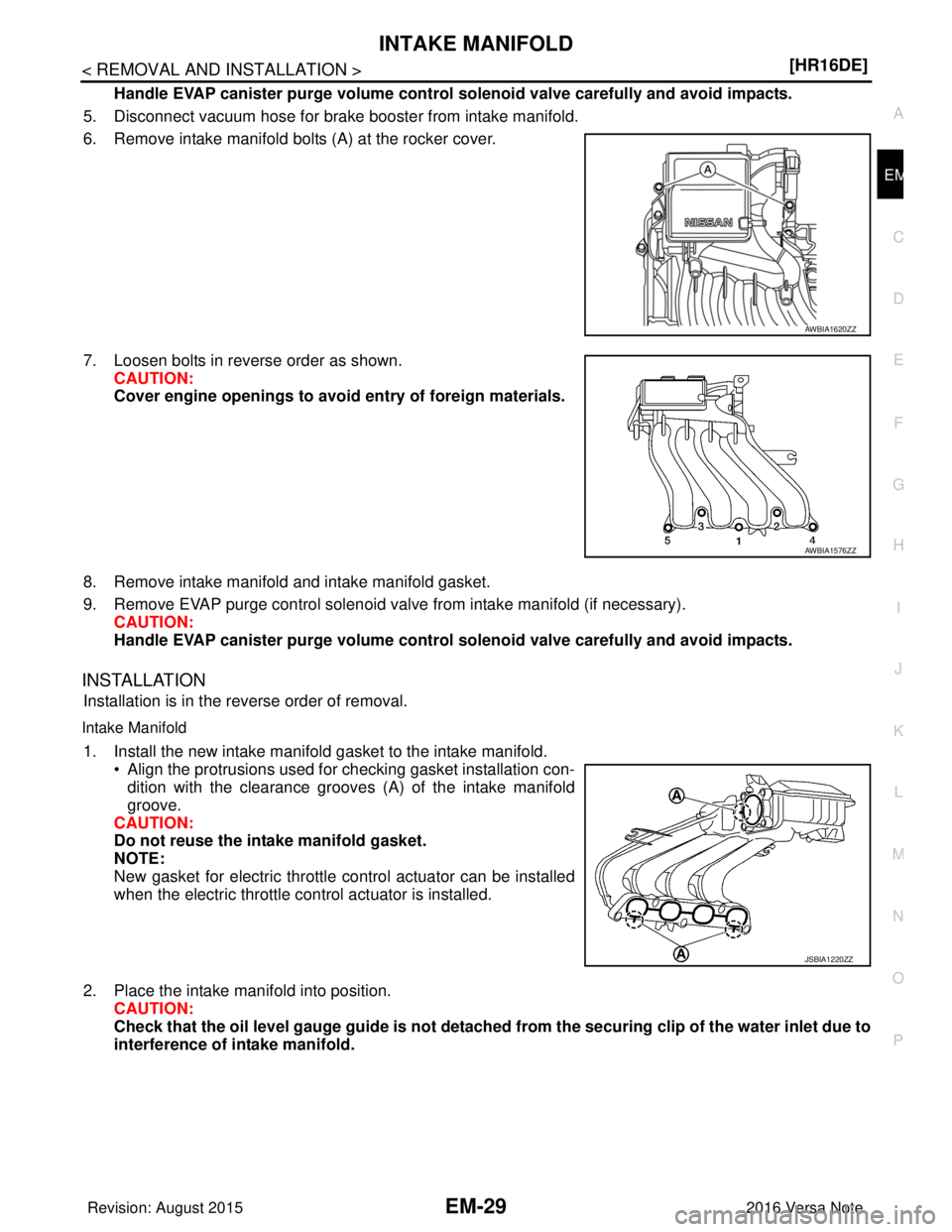
6. Remove intake manifold bolts (A) at the rocker cover.
7. Loosen bolts in reverse order as shown. CAUTION:
Cover engine openings to avoid entry of foreign materials.
8. Remove intake manifold and intake manifold gasket.
9. Remove EVAP purge control solenoid valve from intake manifold (if necessary). CAUTION:
Handle EVAP canister purge volume control solenoid valve carefully and avoid impacts.
INSTALLATION
Installation is in the reverse order of removal.
Intake Manifold
1. Install the new intake manifold gasket to the intake manifold.
• Align the protrusions used for checking gasket installation con-dition with the clearance grooves (A) of the intake manifold
groove.
CAUTION:
Do not reuse the intake manifold gasket.
NOTE:
New gasket for electric throttle control actuator can be installed
when the electric throttle control actuator is installed.
2. Place the intake manifold into position. CAUTION:
Check that the oil level gauge guide is not detached from the securing clip of the water inlet due to
interference of intake manifold.
AWBIA1620ZZ
AWBIA1576ZZ
JSBIA1220ZZ
Revision: August 2015 2016 Versa Note
cardiagn.com
Page 1035 of 3641
EM-34
< REMOVAL AND INSTALLATION >[HR16DE]
OIL PAN AND OIL STRAINER
OIL PAN AND OIL STRAINER
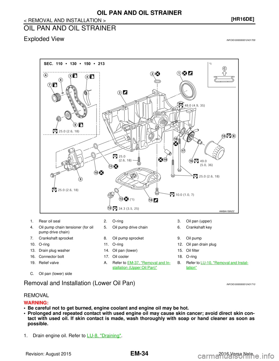
Exploded ViewINFOID:0000000012431709
Removal and Installation (Lower Oil Pan)INFOID:0000000012431710
REMOVAL
WARNING:
• Be careful not to get bu
rned, engine coolant and engine oil may be hot.
• Prolonged and repeated contact with used engi ne oil may cause skin cancer; avoid direct skin con-
tact with used oil. If skin contact is made, wash thoroughly with soap or hand cleaner as soon as
possible.
1. Drain engine oil. Refer to LU-8, "
Draining".
1. Rear oil seal 2. O-ring 3. Oil pan (upper)
4. Oil pump chain tensioner (for oil pump drive chain) 5. Oil pump drive chain
6. Crankshaft key
7. Crankshaft sprocket 8. Oil pump sprocket9. Oil pump
10. O-ring 11. O-ring 12. Oil pan drain plug
13. Drain plug washer 14. Oil pan (lower) 15. Oil filter
16. Connector bolt 17. Oil cooler 18. O-ring
19. Relief valve A. Refer to EM-37, "
Removal and In-
stallation (Upper Oil Pan)"
B. Refer to LU-10, "Removal and Instal-
lation"
C. Oil pan (lower) side
AWBIA1595ZZ
Revision: August 2015 2016 Versa Note
cardiagn.com
Page 1036 of 3641
OIL PAN AND OIL STRAINEREM-35
< REMOVAL AND INSTALLATION > [HR16DE]
C
D
E
F
G H
I
J
K L
M A
EM
NP
O
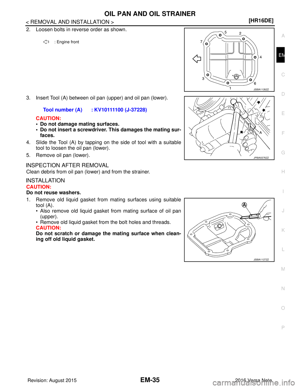
2. Loosen bolts in reverse order as shown.
3. Insert Tool (A) between oil pan (upper) and oil pan (lower).
CAUTION:
• Do not damage mating surfaces.
• Do not insert a screwdriver. This damages the mating sur-faces.
4. Slide the Tool (A) by tapping on the side of tool with a suitable tool to loosen the oil pan (lower).
5. Remove oil pan (lower).
INSPECTION AFTER REMOVAL
Clean debris from oil pan (lower) and from the strainer.
INSTALLATION
CAUTION:
Do not reuse washers.
1. Remove old liquid gasket from mating surfaces using suitable tool (A).
• Also remove old liquid gasket from mating surface of oil pan(upper).
• Remove old liquid gasket from the bolt holes and threads.
CAUTION:
Do not scratch or damage th e mating surface when clean-
ing off old liquid gasket.
: Engine front
JSBIA1126ZZ
Tool number (A) : KV10111100 (J-37228)
JPBIA0276ZZ
JSBIA1127ZZ
Revision: August 2015 2016 Versa Note
cardiagn.com
Page 1037 of 3641
EM-36
< REMOVAL AND INSTALLATION >[HR16DE]
OIL PAN AND OIL STRAINER
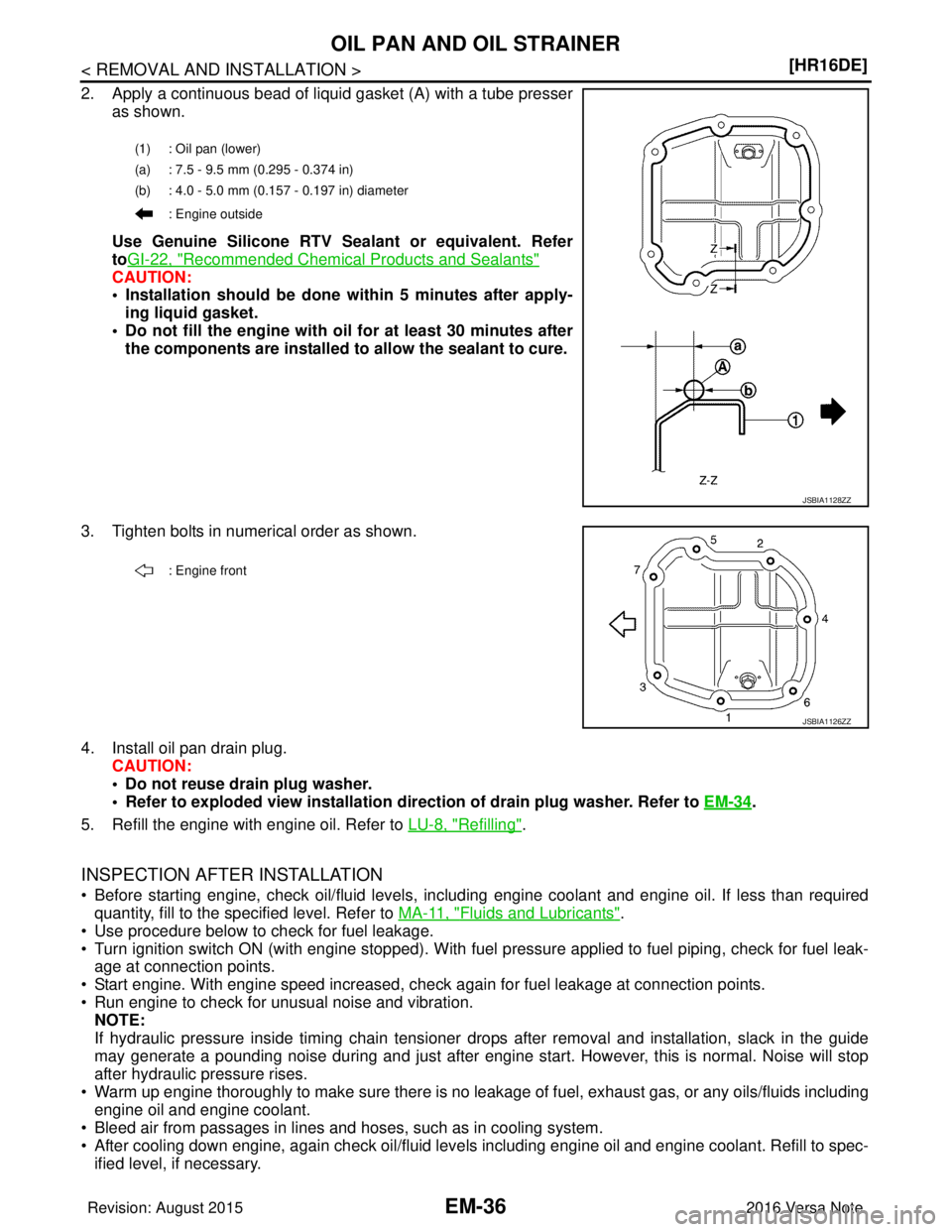
2. Apply a continuous bead of liquid gasket (A) with a tube presser
as shown.
Use Genuine Silicone RTV S ealant or equivalent. Refer
to GI-22, "
Recommended Chemical Products and Sealants"
CAUTION:
• Installation should be done within 5 minutes after apply-
ing liquid gasket.
• Do not fill the engine with oil for at least 30 minutes after
the components are installed to allow the sealant to cure.
3. Tighten bolts in numerical order as shown.
4. Install oil pan drain plug. CAUTION:
• Do not reuse drain plug washer.
• Refer to exploded view installation di rection of drain plug washer. Refer to EM-34
.
5. Refill the engine with engine oil. Refer to LU-8, "
Refilling".
INSPECTION AFTER INSTALLATION
• Before starting engine, check oil/fluid levels, including engine coolant and engine oil. If less than required
quantity, fill to the specified level. Refer to MA-11, "
Fluids and Lubricants".
• Use procedure below to check for fuel leakage.
• Turn ignition switch ON (with engine stopped). With fuel pressure applied to fuel piping, check for fuel leak- age at connection points.
• Start engine. With engine speed increased, che ck again for fuel leakage at connection points.
• Run engine to check for unusual noise and vibration. NOTE:
If hydraulic pressure inside timing chain tensioner drops after removal and installation, slack in the guide
may generate a pounding noise during and just after engine start. However, this is normal. Noise will stop
after hydraulic pressure rises.
• Warm up engine thoroughly to make sure there is no leakage of fuel, exhaust gas, or any oils/fluids including engine oil and engine coolant.
• Bleed air from passages in lines and hoses, such as in cooling system.
• After cooling down engine, again check oil/fluid levels including engine oil and engine coolant. Refill to spec-
ified level, if necessary.
(1) : Oil pan (lower)
(a) : 7.5 - 9.5 mm (0.295 - 0.374 in)
(b) : 4.0 - 5.0 mm (0.157 - 0.197 in) diameter
: Engine outside
JSBIA1128ZZ
: Engine front
JSBIA1126ZZ
Revision: August 2015 2016 Versa Note
cardiagn.com
Page 1038 of 3641
OIL PAN AND OIL STRAINEREM-37
< REMOVAL AND INSTALLATION > [HR16DE]
C
D
E
F
G H
I
J
K L
M A
EM
NP
O
• Summary of the inspection items:
*Power steering fluid, brake fluid, etc.
Removal and Installation (Upper Oil Pan)INFOID:0000000012431711
NOTE:
The oil strainer is included in the oil pan (upper) and cannot be removed.
REMOVAL
1. Remove the oil pan (lower). Refer to
EM-34, "Removal and Installation (Lower Oil Pan)".
2. Remove oil pump sprocket and crankshaft sprocket together with oil pump drive chain. Refer to EM-51,
"Removal and Installation".
3. Remove oil pan (upper).
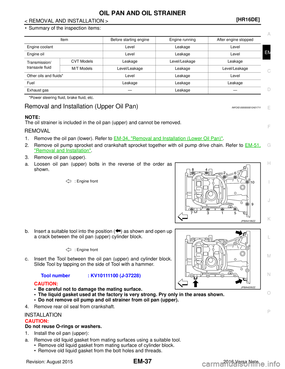
a. Loosen oil pan (upper) bolts in the reverse of the order as shown.
b. Insert a suitable tool into the position ( ) as shown and open up a crack between the oil pan (upper) cylinder block.
c. Insert the Tool between the oil pan (upper) and cylinder block. Slide Tool by tapping on the side of Tool with a hammer.
CAUTION:
• Be careful not to damage the mating surface.
• The liquid gasket used at the factory is very strong. Pry only in the areas shown.
• Do not remove oil pump and oil strainer from oil pan (upper).
4. Remove rear oil seal from crankshaft.
INSTALLATION
CAUTION:
Do not reuse O-rings or washers.
1. Install the oil pan (upper):
a. Remove old liquid gasket from mating surfaces using a suitable tool. • Remove old liquid gasket from mating surface of cylinder block.
• Remove old liquid gasket from the bolt holes and threads.
Item Before starting engine Engine runningAfter engine stopped
Engine coolant LevelLeakage Level
Engine oil LevelLeakage Level
Transmission/
transaxle fluid CVT Models
LeakageLevel/Leakage Leakage
M/T Models Level/Leakage LeakageLevel/Leakage
Other oils and fluids* LevelLeakage Level
Fuel LeakageLeakageLeakage
Exhaust gas —Leakage —
: Engine front
JPBIA4199ZZ
: Engine front
Tool number : KV10111100 (J-37228)
JPBIA4200ZZ
Revision: August 2015 2016 Versa Note
cardiagn.com
Page 1039 of 3641
EM-38
< REMOVAL AND INSTALLATION >[HR16DE]
OIL PAN AND OIL STRAINER
CAUTION:
Do not scratch or damage the mating
surfaces when cleaning off liquid gasket.
b. Install O-ring to the cylinder block.
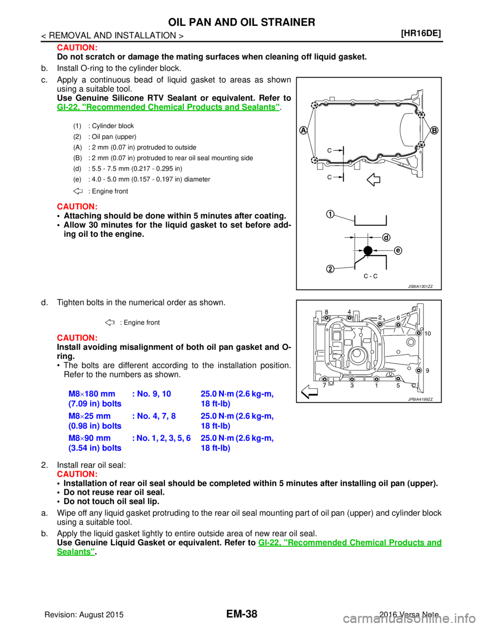
c. Apply a continuous bead of liquid gasket to areas as shown using a suitable tool.
Use Genuine Silicone RTV Sealant or equivalent. Refer to
GI-22, "
Recommended Chemical Products and Sealants".
CAUTION:
• Attaching should be done wit hin 5 minutes after coating.
• Allow 30 minutes for the liquid gasket to set before add-
ing oil to the engine.
d. Tighten bolts in the numerical order as shown. CAUTION:
Install avoiding misalignment of both oil pan gasket and O-
ring.
• The bolts are different according to the installation position.
Refer to the numbers as shown.
2. Install rear oil seal: CAUTION:
• Installation of rear oil seal should be completed within 5 minutes after installing oil pan (upper).
• Do not reuse rear oil seal.
• Do not touch oil seal lip.
a. Wipe off any liquid gasket protruding to the rear oil seal mounting part of oil pan (upper) and cylinder block using a suitable tool.
b. Apply the liquid gasket lightly to entire outside area of new rear oil seal. Use Genuine Liquid Gasket or equivalent. Refer to GI-22, "
Recommended Chemical Products and
Sealants".
(1) : Cylinder block
(2) : Oil pan (upper)
(A) : 2 mm (0.07 in) protruded to outside
(B) : 2 mm (0.07 in) protruded to rear oil seal mounting side
(d) : 5.5 - 7.5 mm (0.217 - 0.295 in)
(e) : 4.0 - 5.0 mm (0.157 - 0.197 in) diameter
: Engine front
JSBIA1301ZZ
: Engine front
M8×180 mm
(7.09 in) bolts : No. 9, 10 25.0 N·m (2.6 kg-m,
18 ft-lb)
M8 ×25 mm
(0.98 in) bolts : No. 4, 7, 8 25.0 N·m (2.6 kg-m,
18 ft-lb)
M8 ×90 mm
(3.54 in) bolts : No. 1, 2, 3, 5, 6 25.0 N·m (2.6 kg-m,
18 ft-lb)JPBIA4199ZZ
Revision: August 2015 2016 Versa Note
cardiagn.com
Page 1040 of 3641
OIL PAN AND OIL STRAINEREM-39
< REMOVAL AND INSTALLATION > [HR16DE]
C
D
E
F
G H
I
J
K L
M A
EM
NP
O
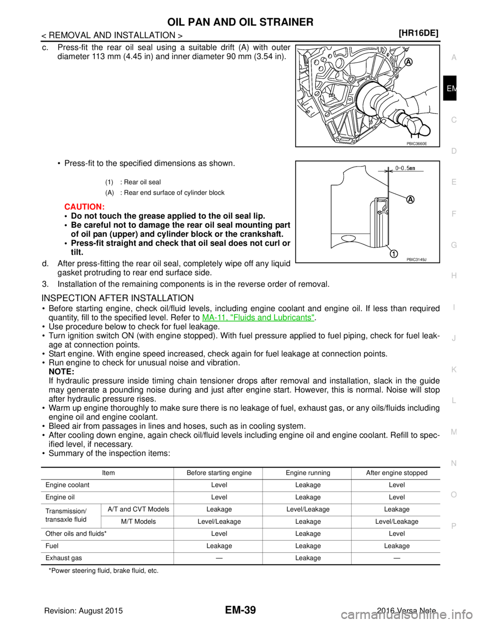
c. Press-fit the rear oil seal using a suitable drift (A) with outer
diameter 113 mm (4.45 in) and inner diameter 90 mm (3.54 in).
• Press-fit to the specified dimensions as shown.
CAUTION:
• Do not touch the grease applied to the oil seal lip.
• Be careful not to damage the rear oil seal mounting partof oil pan (upper) and cylinder block or the crankshaft.
• Press-fit straight and check that oil seal does not curl or tilt.
d. After press-fitting the rear oil seal, completely wipe off any liquid gasket protruding to rear end surface side.
3. Installation of the remaining components is in the reverse order of removal.
INSPECTION AFTER INSTALLATION
• Before starting engine, check oil/fluid levels, includi ng engine coolant and engine oil. If less than required
quantity, fill to the specified level. Refer to MA-11, "
Fluids and Lubricants".
• Use procedure below to check for fuel leakage.
• Turn ignition switch ON (with engine stopped). With fuel pressure applied to fuel piping, check for fuel leak- age at connection points.
• Start engine. With engine speed increased, check again for fuel leakage at connection points.
• Run engine to check for unusual noise and vibration. NOTE:
If hydraulic pressure inside timing chain tensioner drops after removal and installation, slack in the guide
may generate a pounding noise during and just after engine start. However, this is normal. Noise will stop
after hydraulic pressure rises.
• Warm up engine thoroughly to make sure there is no leakage of fuel, exhaust gas, or any oils/fluids including engine oil and engine coolant.
• Bleed air from passages in lines and hoses, such as in cooling system.
• After cooling down engine, again check oil/fluid levels including engine oil and engine coolant. Refill to spec- ified level, if necessary.
• Summary of the inspection items:
*Power steering fluid, brake fluid, etc.
PBIC3660E
(1) : Rear oil seal
(A) : Rear end surface of cylinder block
PBIC3149J
Item Before starting engine Engine runningAfter engine stopped
Engine coolant LevelLeakage Level
Engine oil LevelLeakage Level
Transmission/
transaxle fluid A/T and CVT Models
LeakageLevel/Leakage Leakage
M/T Models Level/Leakage LeakageLevel/Leakage
Other oils and fluids* LevelLeakage Level
Fuel LeakageLeakageLeakage
Exhaust gas —Leakage —
Revision: August 2015 2016 Versa Note
cardiagn.com