2016 NISSAN NOTE air conditioning
[x] Cancel search: air conditioningPage 2327 of 3641
MA-12
< PERIODIC MAINTENANCE >
RECOMMENDED FLUIDS AND LUBRICANTS
Engine Oil Recommendation
INFOID:0000000012432246
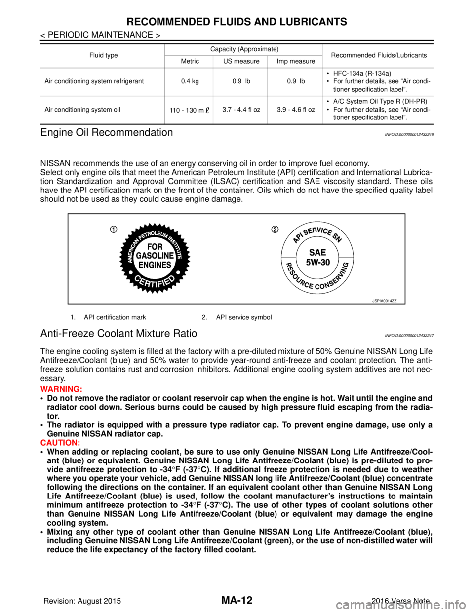
NISSAN recommends the use of an energy conservi ng oil in order to improve fuel economy.
Select only engine oils that meet the American Petroleum Institute (API) certification and International Lubrica-
tion Standardization and Approval Committee (ILSAC) ce rtification and SAE viscosity standard. These oils
have the API certification mark on the front of the container. Oils whic h do not have the specified quality label
should not be used as they could cause engine damage.
Anti-Freeze Coolant Mixture RatioINFOID:0000000012432247
The engine cooling system is filled at the factory with a pre-diluted mixture of 50% Genuine NISSAN Long Life
Antifreeze/Coolant (blue) and 50% water to provide year-round anti-freeze and coolant protection. The anti-
freeze solution contains rust and corrosion inhibitors. Additional engine cooling system additives are not nec-
essary.
WARNING:
• Do not remove the radiator or coolant reservoir cap when the engine is hot. Wait until the engine and radiator cool down. Serious burns could be caused by high pressure fluid escaping from the radia-
tor.
• The radiator is equipped with a pressure type radiator cap. To prevent engine damage, use only a
Genuine NISSAN radiator cap.
CAUTION:
• When adding or replacing coolant, be sure to use only Genuine NISSAN Lo ng Life Antifreeze/Cool-
ant (blue) or equivalent. Genuine NISSAN Long Life Antifreeze/Coolant (blue) is pre-diluted to pro-
vide antifreeze protection to -34 °F (-37 °C). If additional freeze protect ion is needed due to weather
where you operate your vehicle, add Genuine NISSAN long life Antifreeze/Coolant (blue) concentrate
following the directions on the container. If an equivalent coolant other than Genuine NISSAN Long
Life Antifreeze/Coolant (blue) is used, follow the coolant manufact urer’s instructions to maintain
minimum antifreeze protection to -34 °F (-37 °C). The use of other types of coolant solutions other
than Genuine NISSAN Long Life Antifreeze/Coolant (blue) or equivalent may damage the engine
cooling system.
• Mixing any other type of coolant other than Genuine NISSAN Long Life Antifreeze/Coolant (blue),
including Genuine NISSAN Long Life Antifreeze/Coolant (green), or the use of non-distilled water will
reduce the life expectancy of the factory filled coolant.
Air conditioning system refrigerant 0.4 kg0.9 lb 0.9 lb• HFC-134a (R-134a)
• For further details, see “Air condi-
tioner specification label”.
Air conditioning system oil 110 - 130 m3.7 - 4.4 fl oz 3.9 - 4.6 fl oz • A/C System Oil Type R (DH-PR)
• For further details, see “Air condi-
tioner specification label”.
Fluid type
Capacity (Approximate)
Recommended Fluids/Lubricants
Metric US measure Imp measure
1. API certification mark 2. API service symbol
JSPIA0014ZZ
Revision: August 2015 2016 Versa Note
cardiagn.com
Page 3202 of 3641
STC-18
< DTC/CIRCUIT DIAGNOSIS >
C1601 BATTERY POWER SUPPLY
DTC/CIRCUIT DIAGNOSIS
C1601 BATTERY POWER SUPPLY
DTC LogicINFOID:0000000012431953
DTC DETECTION LOGIC
DTC CONFIRMATION PROCEDURE
1.PRECONDITIONING
If “DTC CONFIRMATION PROCEDURE” has been previously conducted, always turn ignition switch OFF and
wait at least 10 seconds before conducting the next test.
>> GO TO 2.
2.DTC REPRODUCTION PROCEDURE
With CONSULT
1. Turn the ignition switch OFF to ON.
2. Perform “Self Diagnostic Result” of “EPS”
Is DTC
“C1601” detected?
YES >> Proceed to diagnosis procedure. Refer to STC-18, "Diagnosis Procedure".
NO >> Inspection End.
Diagnosis ProcedureINFOID:0000000012431954
Regarding Wiring Diagram information, refer to STC-11, "Wiring Diagram".
1.CHECK EPS CONTROL UNIT GROUND CIRCUIT
1. Turn ignition switch OFF.
2. Disconnect EPS control unit harness connector.
3. Check continuity between EPS contro l unit harness connector terminal and ground.
4. Connect EPS control unit harness connector.
Is the inspection result normal?
YES >> GO TO 2.
NO >> Repair open circuit or short to ground or short to power in harness or connectors.
2.CHECK EPS CONTROL UNIT PO WER SUPPLY CIRCUIT (1)
1. Check voltage between EPS control unit harness connector terminal and ground.
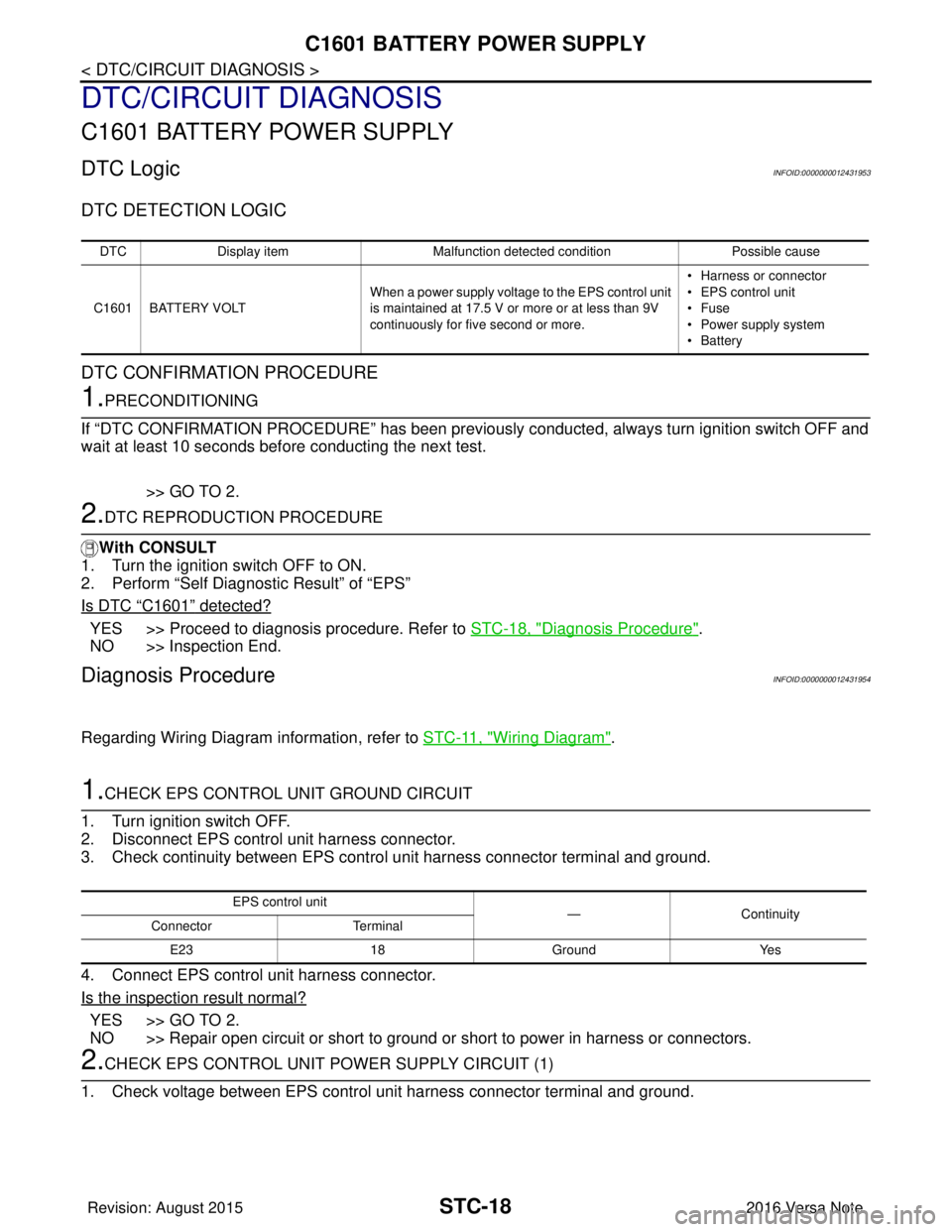
DTC Display item Malfunction detected condition Possible cause
C1601 BATTERY VOLT When a power supply voltage to the EPS control unit
is maintained at 17.5 V or more or at less than 9V
continuously for five second or more. • Harness or connector
• EPS control unit
•Fuse
• Power supply system
•Battery
EPS control unit
—Con tin uit y
Connector Terminal
E23 18Ground Yes
Revision: August 2015 2016 Versa Note
cardiagn.com
Page 3207 of 3641
C1606 EPS MOTORSTC-23
< DTC/CIRCUIT DIAGNOSIS >
C
DE
F
H I
J
K L
M A
B
STC
N
O P
C1606 EPS MOTOR
DTC LogicINFOID:0000000012431957
DTC DETECTION LOGIC
DTC CONFIRMATION PROCEDURE
1.PRECONDITIONING
If “DTC CONFIRMATION PROCEDURE” has been previously conducted, always turn ignition switch OFF and
wait at least 10 seconds before conducting the next test.
>> GO TO 2.
2.DTC REPRODUCTION PROCEDURE
With CONSULT
1. Turn the ignition switch OFF to ON.
2. Perform “Self Diagnostic Result” of “EPS”.
Is DTC
“C1606” detected?
YES >> Proceed to diagnosis procedure. Refer to STC-23, "Diagnosis Procedure".
NO >> Inspection End.
Diagnosis ProcedureINFOID:0000000012431958
1.CHECK EPS MOTOR
Check the EPS motor. Refer to STC-23, "
Component Inspection".
Is the inspection result normal?
YES >> GO TO 2.
NO >> EPS motor is malfunction. Replace steering column assembly. Refer to ST-9, "
Exploded View".
2.CHECK CONNECTOR
1. Turn ignition switch OFF.
2. Disconnect EPS motor harness connector.
3. Check terminal for deformation, disconnection, looseness, and so on. If any malfunction is found, repair or replace terminal.
Is the inspection result normal?
YES >> Replace EPS control unit. Refer to STC-37, "Removal and Installation".
NO >> Repair or replace malfunctioning component.
Component Inspection INFOID:0000000012431959
1.CHECK EPS MOTOR
1. Turn the ignition switch OFF.
2. Disconnect EPS motor harness connector.
3. Check resistance between EPS motor connector terminals.
Is the inspection result normal?
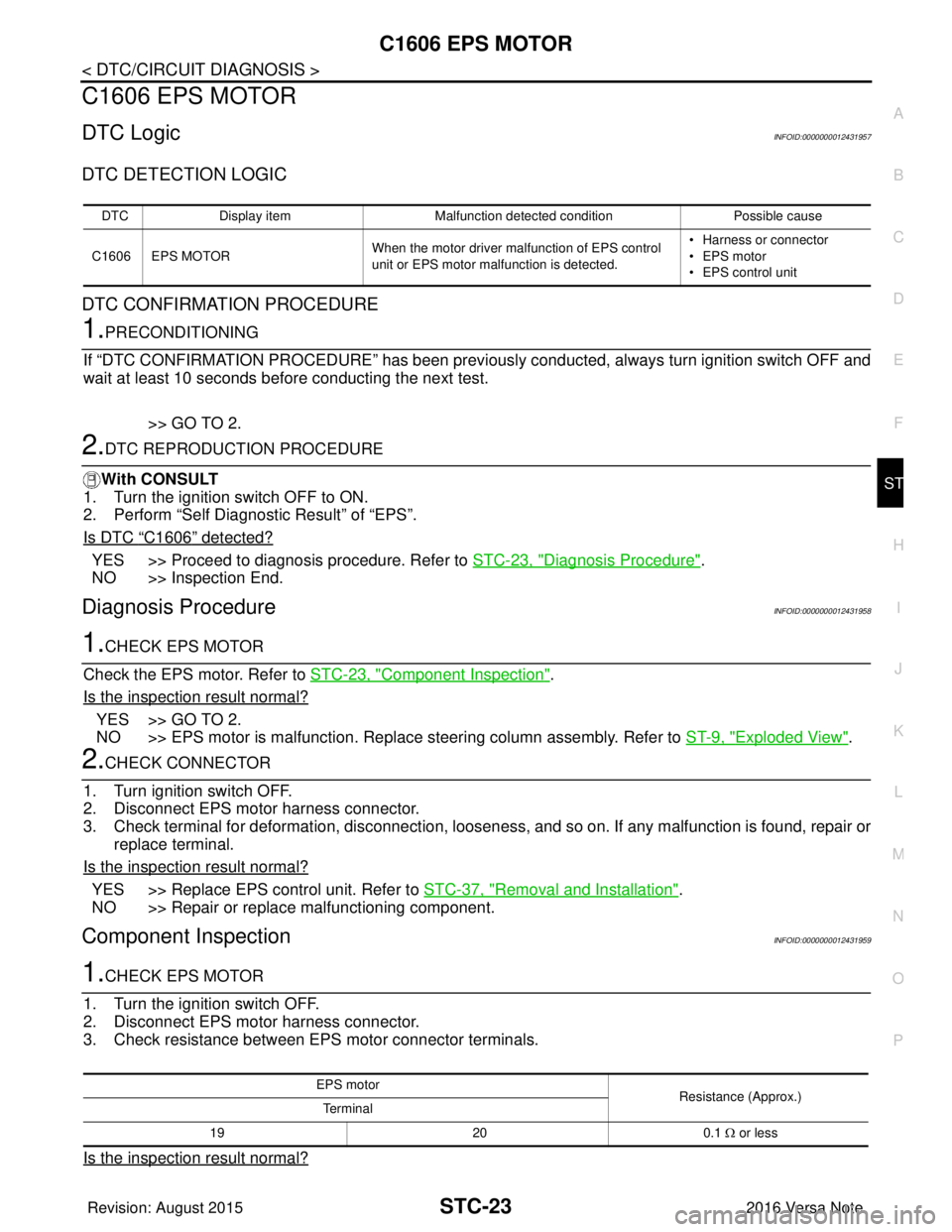
DTC Display item Malfunction detected condition Possible cause
C1606 EPS MOTOR When the motor driver malfunction of EPS control
unit or EPS motor malfunction is detected. • Harness or connector
• EPS motor
• EPS control unit
EPS motor
Resistance (Approx.)
Te r m i n a l
19 200.1 Ω or less
Revision: August 2015 2016 Versa Note
cardiagn.com
Page 3209 of 3641
C1607, C1608 EPS CONTROL UNIT
STC-25
< DTC/CIRCUIT DIAGNOSIS >
C
D E
F
H I
J
K L
M A
B
STC
N
O P
C1607, C1608 EPS CONTROL UNIT
DTC LogicINFOID:0000000012431960
DTC DETECTION LOGIC
DTC CONFIRMATION PROCEDURE
1.PRECONDITIONING
If “DTC CONFIRMATION PROCEDURE” has been previously conducted, always turn ignition switch OFF and
wait at least 10 seconds before conducting the next test.
>> GO TO 2.
2.DTC REPRODUCTION PROCEDURE
With CONSULT
1. Turn the ignition switch OFF to ON.
2. Perform “Self Diagnostic Result” of “EPS”.
Is DTC
“C1607” or “C1608” detected?
YES >> Proceed to diagnosis procedure. Refer to STC-25, "Diagnosis Procedure".
NO >> Inspection End.
Diagnosis ProcedureINFOID:0000000012431961
1.PERFORM SELF-DIAGNOSIS
With CONSULT
1. Turn the ignition switch OFF to ON.
2. Erase “Self Diagnostic Result” of “EPS”.
3. Perform “Self Diagnostic Result” of “EPS”.
Is DTC
“C1607” or “C1608” detected?
YES >> Replace EPS control unit. Refer to STC-37, "Removal and Installation".
NO >> Check EPS control unit pin terminals for damage or loose connection with harness connector. If
any item are damaged, repair or replace malfunctioning component.
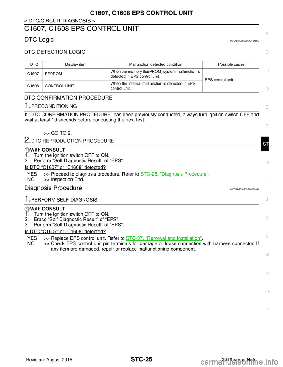
DTC Display item Malfunction detected condition Possible cause
C1607 EEPROM When the memory (EEPROM)
system malfunction is
detected in EPS control unit.
EPS control unit
C1608 CONTROL UNIT When the internal malfunction is detected in EPS
control unit.
Revision: August 2015
2016 Versa Note
cardiagn.com
Page 3210 of 3641
STC-26
< DTC/CIRCUIT DIAGNOSIS >
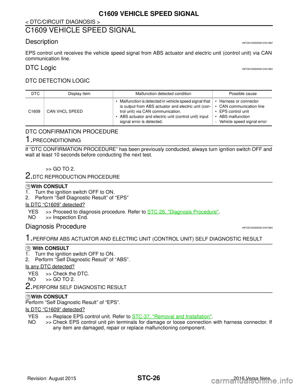
C1609 VEHICLE SPEED SIGNAL
C1609 VEHICLE SPEED SIGNAL
DescriptionINFOID:0000000012431962
EPS control unit receives the vehicle speed signal from ABS actuator and electric unit (control unit) via CAN
communication line.
DTC LogicINFOID:0000000012431963
DTC DETECTION LOGIC
DTC CONFIRMATION PROCEDURE
1.PRECONDITIONING
If “DTC CONFIRMATION PROCEDURE” has been previously conducted, always turn ignition switch OFF and
wait at least 10 seconds before conducting the next test.
>> GO TO 2.
2.DTC REPRODUCTION PROCEDURE
With CONSULT
1. Turn the ignition switch OFF to ON.
2. Perform “Self Diagnostic Result” of “EPS”
Is DTC
“C1609” detected?
YES >> Proceed to diagnosis procedure. Refer to STC-26, "Diagnosis Procedure".
NO >> Inspection End.
Diagnosis ProcedureINFOID:0000000012431964
1.PERFORM ABS ACTUATOR AND ELECTRIC UNIT (CONTROL UNIT) SELF DIAGNOSTIC RESULT
With CONSULT
1. Turn the ignition switch OFF to ON.
2. Perform “Self Diagnostic Result” of “ABS”.
Is any DTC detected?
YES >> Check the DTC.
NO >> GO TO 2.
2.PERFORM SELF DIAGNOSTIC RESULT
With CONSULT
Perform “Self Diagnostic Result” of “EPS”.
Is DTC
“C1609” detected?
YES >> Replace EPS control unit. Refer to STC-37, "Removal and Installation".
NO >> Check EPS control unit pin terminals for damage or loose connection with harness connector. If any item are damaged, repair or replace malfunctioning component.
DTC Display item Malfunction detected condition Possible cause
C1609 CAN VHCL SPEED • Malfunction is detected in vehicle speed signal that
is output from ABS actuator and electric unit (con-
trol unit) via CAN communication.
• ABS actuator and electric unit (control unit) input signal error is detected. • Harness or connector
• CAN communication line
• EPS control unit
• ABS malfunction
- Vehicle speed signal error
Revision: August 2015
2016 Versa Note
cardiagn.com
Page 3211 of 3641
C1610 ENGINE STATUS SIGNALSTC-27
< DTC/CIRCUIT DIAGNOSIS >
C
DE
F
H I
J
K L
M A
B
STC
N
O P
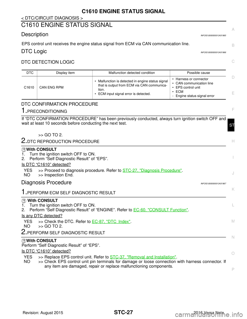
C1610 ENGINE STATUS SIGNAL
DescriptionINFOID:0000000012431965
EPS control unit receives the engine status signal from ECM via CAN communication line.
DTC LogicINFOID:0000000012431966
DTC DETECTION LOGIC
DTC CONFIRMATION PROCEDURE
1.PRECONDITIONING
If “DTC CONFIRMATION PROCEDURE” has been previously conducted, always turn ignition switch OFF and
wait at least 10 seconds before conducting the next test.
>> GO TO 2.
2.DTC REPRODUCTION PROCEDURE
With CONSULT
1. Turn the ignition switch OFF to ON.
2. Perform “Self Diagnostic Result” of “EPS”.
Is DTC
“C1610” detected?
YES >> Proceed to diagnosis procedure. Refer to STC-27, "Diagnosis Procedure".
NO >> Inspection End.
Diagnosis ProcedureINFOID:0000000012431967
1.PERFORM ECM SELF DIAGNOSTIC RESULT
With CONSULT
1. Turn the ignition switch OFF to ON.
2. Perform “Self Diagnostic Result” of “ENGINE”. Refer to EC-60, "
CONSULT Function".
Is any DTC detected?
YES >> Check the DTC. Refer to EC-87, "DTCIndex".
NO >> GO TO 2.
2.PERFORM SELF DIAGNOSTIC RESULT
With CONSULT
Perform “Self Diagnostic Result” of “EPS”.
Is DTC
“C1610” detected?
YES >> Replace EPS control unit. Refer to STC-37, "Removal and Installation".
NO >> Check EPS control unit pin terminals for damage or loose connection with harness connector. If
any item are damaged, repair or replace malfunctioning components.
DTC Display item Malfunction detected condition Possible cause
C1610 CAN ENG RPM • Malfunction is detected in engine status signal
that is output from ECM via CAN communica-
tion.
• ECM input signal error is detected. • Harness or connector
• CAN communication line
• EPS control unit
•ECM
- Engine status signal error
Revision: August 2015
2016 Versa Note
cardiagn.com