2016 NISSAN NOTE tire size
[x] Cancel search: tire sizePage 2347 of 3641
MA-32
< PERIODIC MAINTENANCE >
CHASSIS AND BODY MAINTENANCE
GEAR OIL : Refilling
INFOID:0000000012432275
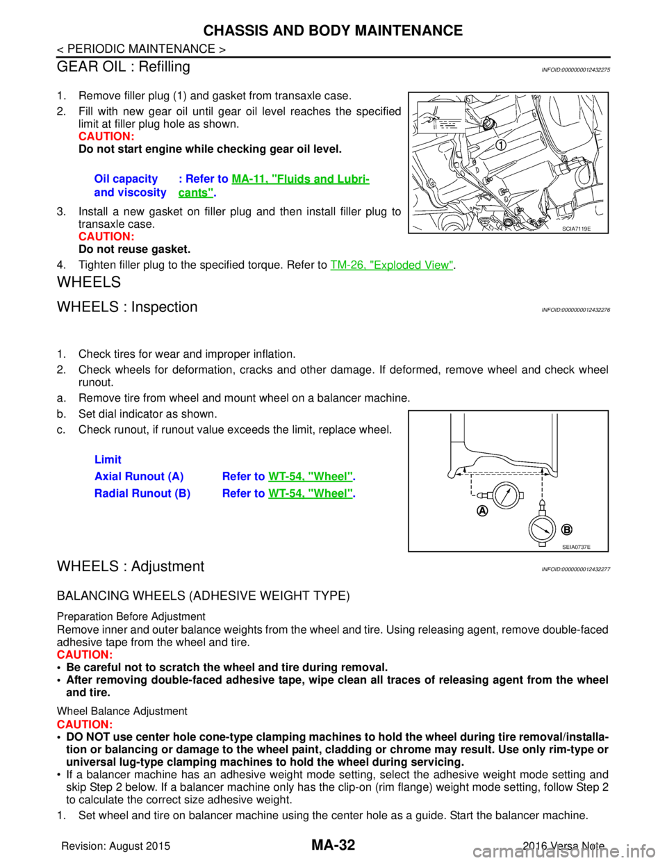
1. Remove filler plug (1) and gasket from transaxle case.
2. Fill with new gear oil until gear oil level reaches the specified limit at filler plug hole as shown.
CAUTION:
Do not start engine whil e checking gear oil level.
3. Install a new gasket on filler plug and then install filler plug to transaxle case.
CAUTION:
Do not reuse gasket.
4. Tighten filler plug to the specified torque. Refer to TM-26, "
Exploded View".
WHEELS
WHEELS : InspectionINFOID:0000000012432276
1. Check tires for wear and improper inflation.
2. Check wheels for deformation, cracks and other dam age. If deformed, remove wheel and check wheel
runout.
a. Remove tire from wheel and mount wheel on a balancer machine.
b. Set dial indicator as shown.
c. Check runout, if runout value exceeds the limit, replace wheel.
WHEELS : AdjustmentINFOID:0000000012432277
BALANCING WHEELS (ADHESIVE WEIGHT TYPE)
Preparation Before Adjustment
Remove inner and outer balance weights from the wheel and tire. Using releasing agent, remove double-faced
adhesive tape from the wheel and tire.
CAUTION:
• Be careful not to scratch the wheel and tire during removal.
• After removing double-faced adh esive tape, wipe clean all traces of releasing agent from the wheel
and tire.
Wheel Balance Adjustment
CAUTION:
• DO NOT use center hole cone-type clamping machines to hold the wheel during tire removal/installa-
tion or balancing or damage to the wheel paint, cladding or chrome may result. Use only rim-type or
universal lug-type clamping machines to hold the wheel during servicing.
• If a balancer machine has an adhesive weight mode se tting, select the adhesive weight mode setting and
skip Step 2 below. If a balancer machine only has the clip -on (rim flange) weight mode setting, follow Step 2
to calculate the correct size adhesive weight.
1. Set wheel and tire on balancer machine using the center hole as a guide. Start the balancer machine. Oil capacity
and viscosity
: Refer to
MA-11, "
Fluids and Lubri-
cants".
SCIA7119E
Limit
Axial Runout (A) Refer to WT-54, "
Wheel".
Radial Runout (B) Refer to WT-54, "
Wheel".
SEIA0737E
Revision: August 2015 2016 Versa Note
cardiagn.com
Page 2348 of 3641
CHASSIS AND BODY MAINTENANCEMA-33
< PERIODIC MAINTENANCE >
C
DE
F
G H
I
J
K L
M B
MA
N
O A
2. For balancer machines that only have a clip-on (rim fl
ange) weight mode setting, follow this step to calcu-
late the correct size adhesive weight to use. W hen inner and outer imbalance values are shown on the
balancer machine indicator, multiply outer imbalance value by 5/3 (1.67) to determine balance weight that
should be used. Select the outer balance weight with a value closest to the calculated value above and
install in to the designated outer position of or at the designated angle in relation to the wheel and tire.
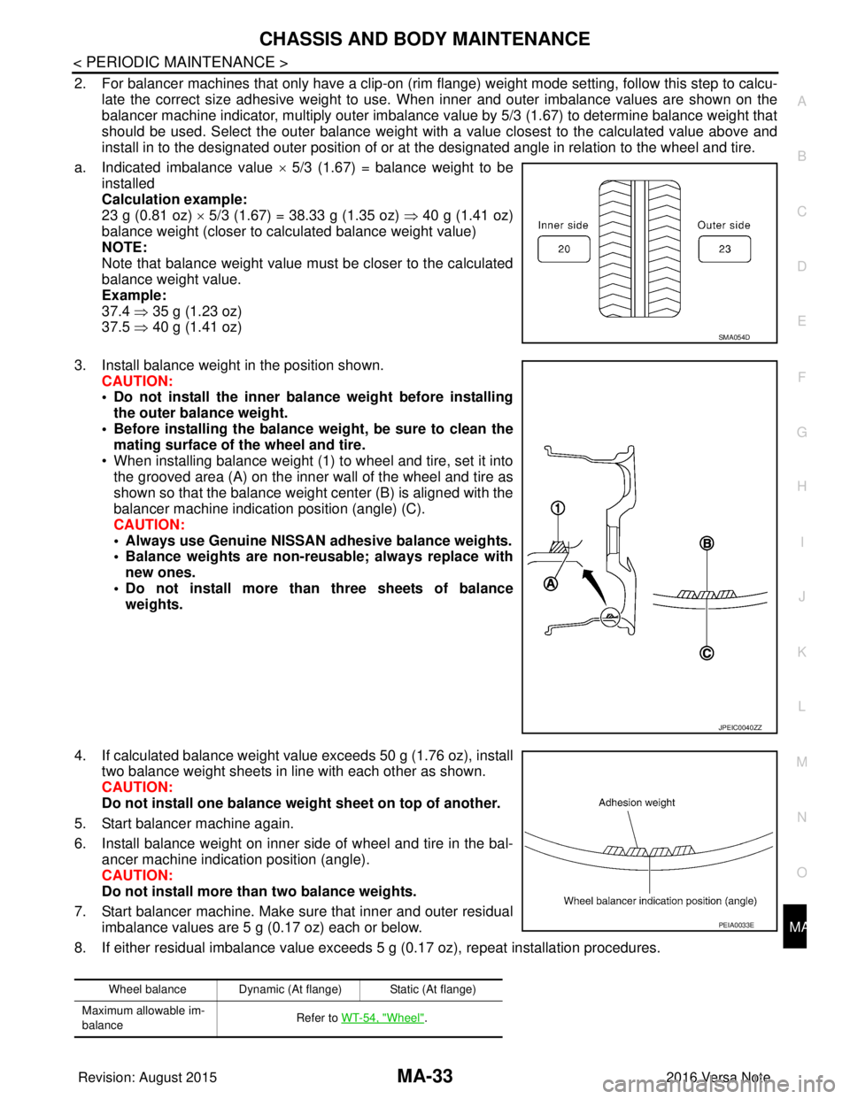
a. Indicated imbalance value × 5/3 (1.67) = balance weight to be
installed
Calculation example:
23 g (0.81 oz) × 5/3 (1.67) = 38.33 g (1.35 oz) ⇒ 40 g (1.41 oz)
balance weight (closer to calculated balance weight value)
NOTE:
Note that balance weight value must be closer to the calculated
balance weight value.
Example:
37.4 ⇒ 35 g (1.23 oz)
37.5 ⇒ 40 g (1.41 oz)
3. Install balance weight in the position shown. CAUTION:
• Do not install the inner bala nce weight before installing
the outer balance weight.
• Before installing the balance weight, be sure to clean the mating surface of the wheel and tire.
• When installing balance weight (1) to wheel and tire, set it into the grooved area (A) on the inner wall of the wheel and tire as
shown so that the balance weight center (B) is aligned with the
balancer machine indication position (angle) (C).
CAUTION:
• Always use Genuine NISSAN adhesive balance weights.
• Balance weights are non-re usable; always replace with
new ones.
• Do not install more than three sheets of balance weights.
4. If calculated balance weight value exceeds 50 g (1.76 oz), install two balance weight sheets in line with each other as shown.
CAUTION:
Do not install one balance weig ht sheet on top of another.
5. Start balancer machine again.
6. Install balance weight on inner side of wheel and tire in the bal- ancer machine indication position (angle).
CAUTION:
Do not install more than two balance weights.
7. Start balancer machine. Make sure that inner and outer residual imbalance values are 5 g (0.17 oz) each or below.
8. If either residual imbalance value exceeds 5 g (0.17 oz), repeat installation procedures.
SMA054D
JPEIC0040ZZ
Wheel balance Dynamic (At flange) Static (At flange)
Maximum allowable im-
balance Refer to WT-54, "
Wheel".
PEIA0033E
Revision: August 2015
2016 Versa Note
cardiagn.com
Page 2743 of 3641
SERVICE DATA AND SPECIFICATIONS (SDS)RSU-15
< SERVICE DATA AND SPECIFICATIONS (SDS)
C
DF
G H
I
J
K L
M A
B
RSU
N
O P
SERVICE DATA AND SPECIFICATIONS (SDS)
SERVICE DATA AND SPECIFICATIONS (SDS)
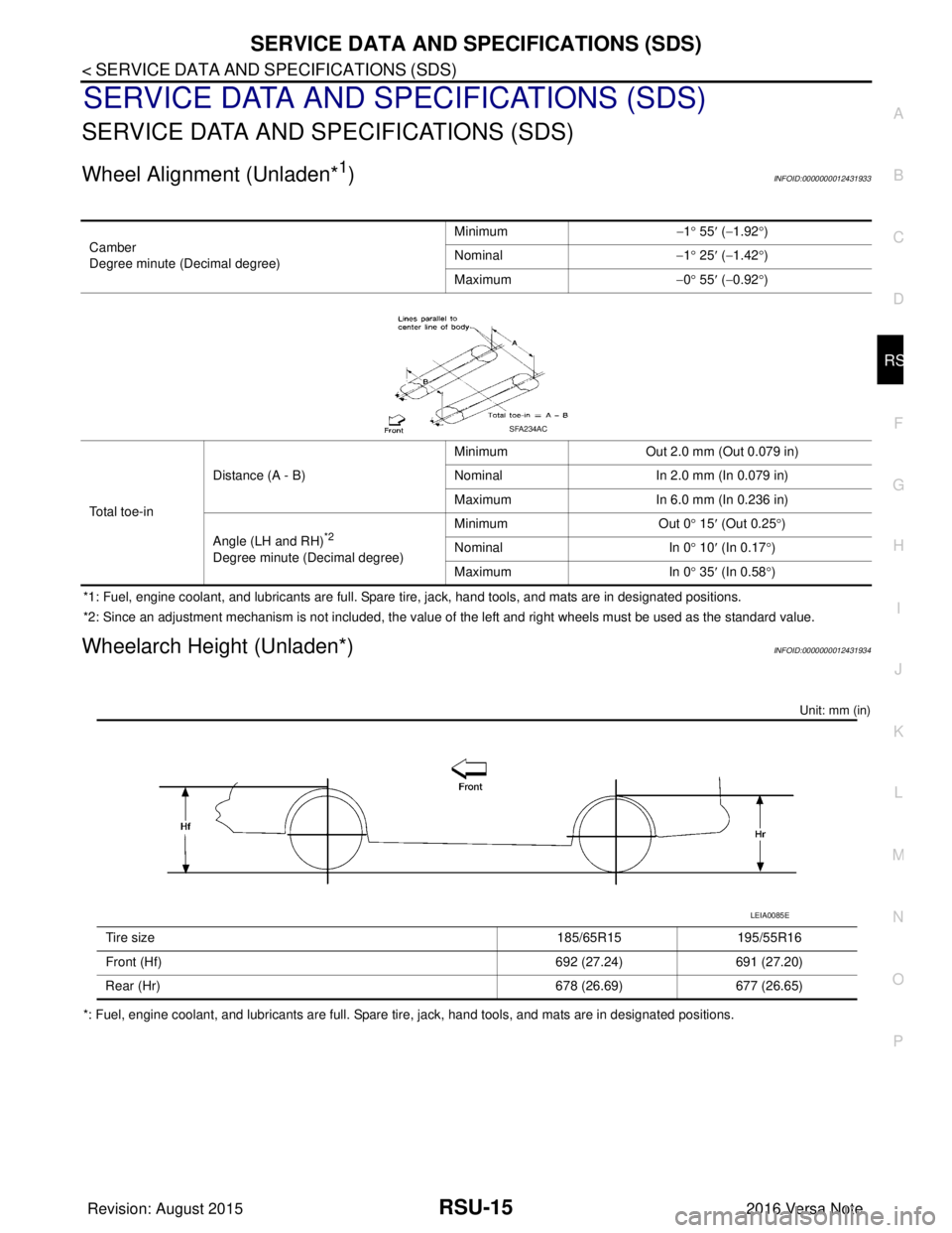
Wheel Alignment (Unladen*1)INFOID:0000000012431933
*1: Fuel, engine coolant, and lubricants are full. Spare tire, jack, hand tools, and mats are in designated positions.
*2: Since an adjustment mechanism is not included, the value of the left and right wheels must be used as the standard value.
Wheelarch Height (Unladen*)INFOID:0000000012431934
Unit: mm (in)
*: Fuel, engine coolant, and lubricants are full. Spare tire, jack, hand tools, and mats are in designated positions. Camber
Degree minute (Decimal degree)
Minimum
−1° 55 ′ ( −1.92 °)
Nominal −1° 25 ′ ( −1.42 °)
Maximum −0° 55 ′ ( −0.92 °)
Total toe-in Distance (A - B)
Minimum
Out 2.0 mm (Out 0.079 in)
Nominal In 2.0 mm (In 0.079 in)
Maximum In 6.0 mm (In 0.236 in)
Angle (LH and RH)
*2
Degree minute (Decimal degree) Minimum Out 0
° 15 ′ (Out 0.25 °)
Nominal In 0° 10 ′ (In 0.17 °)
Maximum In 0° 35 ′ (In 0.58 °)
SFA234AC
Tire size 185/65R15195/55R16
Front (Hf) 692 (27.24)691 (27.20)
Rear (Hr) 678 (26.69)677 (26.65)
LEIA0085E
Revision: August 2015 2016 Versa Note
cardiagn.com
Page 2786 of 3641

NOISE, VIBRATION AND HARSHNESS (NVH) TROUBLESHOOTINGWT-43
< SYMPTOM DIAGNOSIS >
C
DF
G H
I
J
K L
M A
B
WT
N
O P
NOISE, VIBRATION AND HARSHN ESS (NVH) TROUBLESHOOTING
NVH Troubleshooting ChartINFOID:0000000012432464
Use chart below to find the cause of the symptom . If necessary, repair or replace these parts.
×: Applicable
Reference page
WT-44WT-44WT-45WT-54FSU-8—
—
WT-54FSU-5FA X - 6RAX-4RSU-4—
—
FA X - 6BR-7ST-7
Possible cause and SUSPECTED PARTS
Improper installation, looseness
Out-of-round
Imbalance
Incorrect tire pressure
Uneven tire wear
Deformation or damage
Non-uniformity
Incorrect tire size
FRONT AXLE AND FRONT SUSPENSION
REAR AXLE AND REAR SUSPENSION
TIRES
ROAD WHEELS
DRIVE SHAFT
BRAKE
STEERING
Symptom TIRENoise
××××××× × × ××××
Shake ×××××× × × × ××××
Vibration ××××××
Shimmy ×××××××× × × × ××
Shudder ×
××××× × × × × ××
Poor quality ride or
handling ×××××× × × ××
WHEEL Noise
××× × × × × ×××
Shake ××× × × × × ×××
Shimmy, Shudder ×××× ×××××
Poor quality ride or
handling ×× × ×
× × ×
Revision: August 2015 2016 Versa Note
cardiagn.com
Page 2788 of 3641
WHEEL AND TIREWT-45
< PERIODIC MAINTENANCE >
C
DF
G H
I
J
K L
M A
B
WT
N
O P
WHEEL AND TIRE
AdjustmentINFOID:0000000012432466
BALANCING WHEELS (ADH ESIVE WEIGHT TYPE)
Preparation Before Adjustment
Remove inner and outer balance weights from the wheel and tire. Using releasing agent, remove double-faced
adhesive tape from the wheel and tire.
CAUTION:
• Be careful not to scratch the wheel and tire during removal.
• After removing double-faced ad hesive tape, wipe clean all traces of releasing agent from the wheel
and tire.
Wheel Balance Adjustment
CAUTION:
• DO NOT use center hole cone-type clamping machin es to hold the wheel during tire removal/installa-
tion or balancing or damage to the wheel paint, cl adding or chrome may result. Use only rim-type or
universal lug-type clamping machines to hold the wheel during servicing.
• If a balancer machine has an adhesive weight mode setting, select the adhesive weight mode setting and
skip Step 2 below. If a balancer machine only has the clip-on (rim flange) weight mode setting, follow Step 2
to calculate the correct size adhesive weight.
1. Set wheel and tire on balancer machine using the center hole as a guide. Start the balancer machine.
2. For balancer machines that only have a clip-on (rim fl ange) weight mode setting, follow this step to calcu-
late the correct size adhesive weight to use. W hen inner and outer imbalance values are shown on the
balancer machine indicator, multiply outer imbalance value by 5/3 (1.67) to determine balance weight that
should be used. Select the outer balance weight with a value closest to the calculated value above and
install in to the designated outer position of or at the designated angle in relation to the wheel and tire.
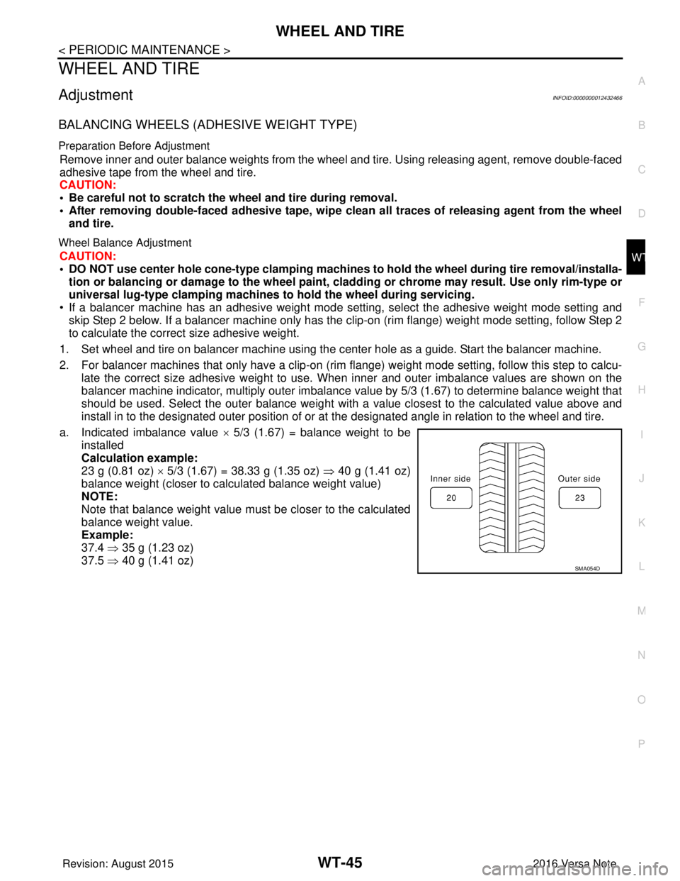
a. Indicated imbalance value × 5/3 (1.67) = balance weight to be
installed
Calculation example:
23 g (0.81 oz) × 5/3 (1.67) = 38.33 g (1.35 oz) ⇒ 40 g (1.41 oz)
balance weight (closer to calculated balance weight value)
NOTE:
Note that balance weight value must be closer to the calculated
balance weight value.
Example:
37.4 ⇒ 35 g (1.23 oz)
37.5 ⇒ 40 g (1.41 oz)
SMA054D
Revision: August 2015 2016 Versa Note
cardiagn.com
Page 2797 of 3641

WT-54
< SERVICE DATA AND SPECIFICATIONS (SDS)
SERVICE DATA AND SPECIFICATIONS (SDS)
SERVICE DATA AND SPECIFICATIONS (SDS)
SERVICE DATA AND SPECIFICATIONS (SDS)
WheelINFOID:0000000012432473
ALUMINUM WHEEL
STEEL WHEEL
Tire Air PressureINFOID:0000000012432474
Unit: kPa (kg/cm2, psi)
ItemLimit
Runout Axial runout
Less than 0.3 mm (0.012 in)
Radial runout
Allowable imbalance Dynamic (At flange)
Less than 5 g (0.17 oz) (one side)
Static (At flange) Less than 10 g (0.35 oz)
Item Limit
Runout Axial runout
Less than 0.8 mm (0.031 in)
Radial runout Less than 0.5 mm (0.020 in)
Allowable imbalance Dynamic (At flange)
Less than 5 g (0.17 oz) (one side)
Static (At flange) Less than 10 g (0.35 oz)
Tire size Cold tire pressure
Front RearSpare
P185/65R15 86H 230 (2.35, 33)230 (2.35, 33) —
P195/55R16 86V 230 (2.35, 33)230 (2.35, 33) —
T125/70D15 ——420 (4.28, 60)
Revision: August 2015 2016 Versa Note
cardiagn.com
Page 3187 of 3641
PRECAUTIONSSTC-3
< PRECAUTION >
C
DE
F
H I
J
K L
M A
B
STC
N
O P
PRECAUTION
PRECAUTIONS
Precaution for Supplemental Restraint System (SRS) "AIR BAG" and "SEAT BELT
PRE-TENSIONER"
INFOID:0000000012431939
The Supplemental Restraint System such as “AIR BAG” and “SEAT BELT PRE-TENSIONER”, used along
with a front seat belt, helps to reduce the risk or severi ty of injury to the driver and front passenger for certain
types of collision. Information necessary to service the system safely is included in the SR and SB section of
this Service Manual.
WARNING:
• To avoid rendering the SRS inoper ative, which could increase the risk of personal injury or death in
the event of a collision which would result in air bag inflation, all maintenance must be performed by
an authorized NISSAN/INFINITI dealer.
• Improper maintenance, including in correct removal and installation of the SRS, can lead to personal
injury caused by unintentional act ivation of the system. For removal of Spiral Cable and Air Bag
Module, see the SR section.
• Do not use electrical test equipm ent on any circuit related to the SRS unless instructed to in this
Service Manual. SRS wiring harnesses can be identi fied by yellow and/or orange harnesses or har-
ness connectors.
PRECAUTIONS WHEN USING POWER TOOLS (AIR OR ELECTRIC) AND HAMMERS
WARNING:
• When working near the Airbag Diagnosis Sensor Un it or other Airbag System sensors with the Igni-
tion ON or engine running, DO NOT use air or el ectric power tools or strike near the sensor(s) with a
hammer. Heavy vibration could activate the sensor( s) and deploy the air bag(s), possibly causing
serious injury.
• When using air or electric power tools or hammers, always switch the Ignition OFF, disconnect the
battery and wait at least three mi nutes before performing any service.
Service Notice and Precautions for EPS SystemINFOID:0000000012431940
• Check the following item when performing the trouble diagnosis:
- Check for possible causes of the malfunction by inte rviewing the customer as to what conditions were
present when the symptom occurred.
- Check if the steering wheel and the EPS control unit are genuine parts.
- Check if the air pressure and size of each tire is correct.
- Check if the installation of the links and suspension components are correct.
- Check if the tires are worn evenly, indicating the wheel alignment is correct.
- Check if the installation of the steering column and t he steering gear are correct. Check for loose bolts, dam-
aged links, cracked boots and leaking grease, etc.
- Check for damage or modification to suspension or body resulting in increased weight or altered ground clearance.
- Check if the battery voltage is proper.
- Check the EPS control unit harness to be sure the harness connectors are fully seated.
• Before connecting or disconnecting the EPS control uni t harness connector, turn ignition switch “OFF” and
disconnect the battery cable from the negative terminal. Battery voltage is applied to the EPS control unit
even if ignition switch is turned “OFF”.
Revision: August 2015 2016 Versa Note
cardiagn.com