2016 NISSAN NOTE EXT-38
[x] Cancel search: EXT-38Page 1623 of 3641
![NISSAN NOTE 2016 Service Repair Manual CO-18
< REMOVAL AND INSTALLATION >[HR16DE]
WATER PUMP
WATER PUMP
Exploded ViewINFOID:0000000012432144
Removal and InstallationINFOID:0000000012432145
WARNING:
Do not remove the radiator cap when the e](/manual-img/5/57363/w960_57363-1622.png "NISSAN NOTE 2016 Service Repair Manual CO-18
< REMOVAL AND INSTALLATION >[HR16DE]
WATER PUMP
WATER PUMP
Exploded ViewINFOID:0000000012432144
Removal and InstallationINFOID:0000000012432145
WARNING:
Do not remove the radiator cap when the e")
CO-18
< REMOVAL AND INSTALLATION >[HR16DE]
WATER PUMP
WATER PUMP
Exploded ViewINFOID:0000000012432144
Removal and InstallationINFOID:0000000012432145
WARNING:
Do not remove the radiator cap when the engine is hot. Serious burns could
occur from high-pressure
engine coolant escaping from the radi ator. Wrap a thick cloth around the radiator cap. Slowly turn it a
quarter of a turn to release built-up pressure. Carefu lly remove radiator cap by turning it all the way.
NOTE:
When removing components such as hoses, tubes/lines, etc. , cap or plug openings to prevent fluid from spill-
ing.
REMOVAL
1. Drain engine coolant from radiator. Refer to CO-8, "Draining Engine Coolant".
CAUTION:
• Perform this step when the engine is cold.
• Do not spill engine coolant on drive belt.
2. Remove front wheel and tire (RH) using power tool. Refer to WT-48, "
Removal and Installation".
3. Remove front fender protector (RH). Refer to EXT-38, "
Removal and Installation".
4. Loosen water pump pulley bolts before loosening belt tension of drive belt.
5. Remove drive belt. Refer to EM-16, "
Removal and Installation".
6. Remove water pump pulley.
7. Remove water pump. • Loosen water pump bolts in reverse order as shown.
• Engine coolant will leak from cylinder block, so have a recep-
tacle ready below.
CAUTION:
• Do not allow water pump vane to contact any other parts.
• Water pump cannot be disassembled and must be replaced as an assembly.
1. Gasket 2. Water pump3. Water pump pulley
JPBIA4104GB
KBIA3393J
Revision: August 2015 2016 Versa Note
cardiagn.com
Page 1756 of 3641
EXL-104
< REMOVAL AND INSTALLATION >
FRONT FOG LAMP
FRONT FOG LAMP
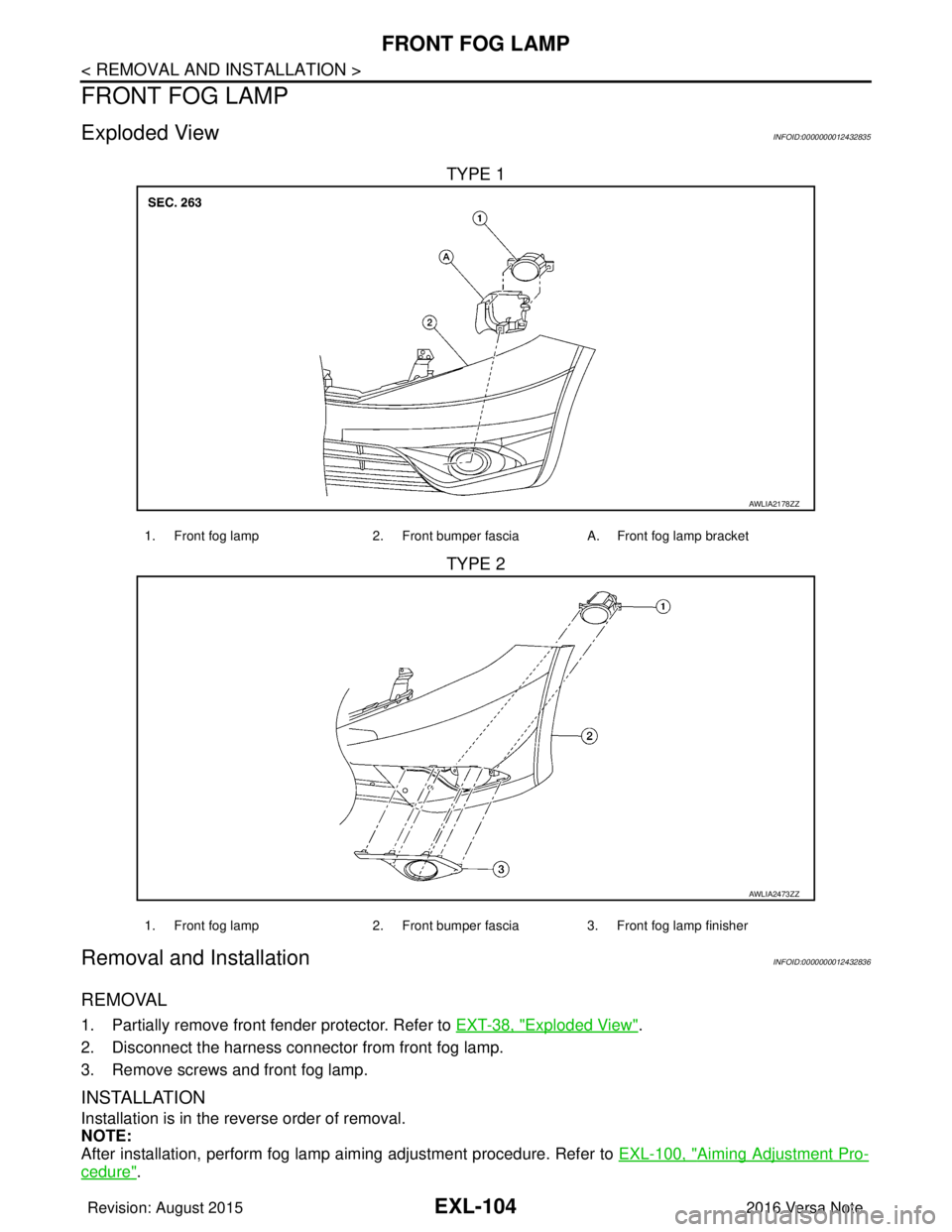
Exploded ViewINFOID:0000000012432835
TYPE 1
TYPE 2
Removal and InstallationINFOID:0000000012432836
REMOVAL
1. Partially remove front fender protector. Refer to EXT-38, "Exploded View".
2. Disconnect the harness connector from front fog lamp.
3. Remove screws and front fog lamp.
INSTALLATION
Installation is in the reverse order of removal.
NOTE:
After installation, perform fog lamp aiming adjustment procedure. Refer to EXL-100, "
Aiming Adjustment Pro-
cedure".
AWLIA2178ZZ
1. Front fog lamp2. Front bumper fasciaA. Front fog lamp bracket
AWLIA2473ZZ
1. Front fog lamp 2. Front bumper fascia3. Front fog lamp finisher
Revision: August 2015 2016 Versa Note
cardiagn.com
Page 1757 of 3641
FRONT FOG LAMPEXL-105
< REMOVAL AND INSTALLATION >
C
DE
F
G H
I
J
K
M A
B
EXL
N
O P
Bulb ReplacementINFOID:0000000012432837
WARNING:
Do not touch bulb by hand while it is lit or right after being turned off. Burning may result.
CAUTION:
• Do not touch the glass surface of the bulb with bare hands or allow oi l or grease to get on it to pre-
vent damage to the bulb.
• Do not leave bulb out of lamp reflector for a long time because dust, moisture smoke, etc. may affect
the performance of lamp. When replacing bulb, be sure to replace it with new one.
REMOVAL
1. Partially remove fender protector. Refer to EXT-38, "Exploded View".
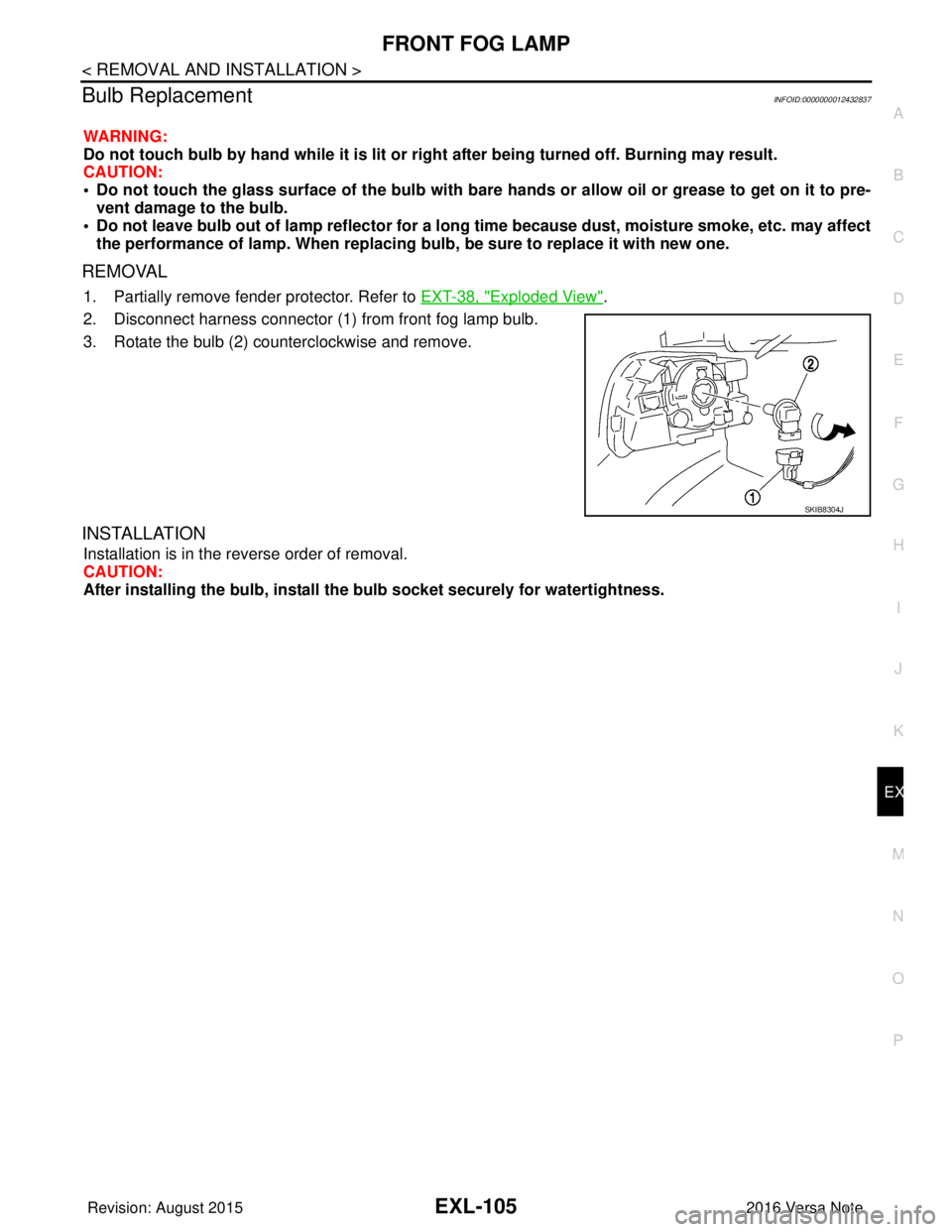
2. Disconnect harness connector (1) from front fog lamp bulb.
3. Rotate the bulb (2) counterclockwise and remove.
INSTALLATION
Installation is in the reverse order of removal.
CAUTION:
After installing the bulb, install the bulb socket securely for watertightness.
SKIB8304J
Revision: August 2015 2016 Versa Note
cardiagn.com
Page 1792 of 3641
FRONT BUMPEREXT-25
< REMOVAL AND INSTALLATION >
C
DE
F
G H
I
J
L
M A
B
EXT
N
O P
2. Remove the four front bumper fascia upper clips.
3. Remove the front under cover. Refer to EXT-39, "
FRONT UNDER COVER : Removal and Installation".
4. Partially remove front fender protectors (LH/RH) at the front edge to access front bumper fascia bolts.
Refer to EXT-38, "
Exploded View".
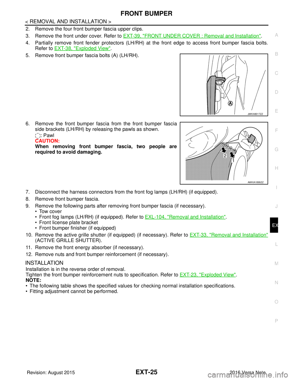
5. Remove front bumper fascia bolts (A) (LH/RH).
6. Remove the front bumper fasci a from the front bumper fascia
side brackets (LH/RH) by releasing the pawls as shown.
: Pawl
CAUTION:
When removing front bumper fascia, two people are
required to avoid damaging.
7. Disconnect the harness connectors from t he front fog lamps (LH/RH) (if equipped).
8. Remove front bumper fascia.
9. Remove the following parts after removing front bumper fascia (if necessary). • Tow cover
• Front fog lamps (LH/RH) (if equipped). Refer to EXL-104, "
Removal and Installation".
• Front license plate bracket
• Front bumper finisher (if equipped)
10. Remove the active grille shutter (if equipped) (if necessary). Refer to EXT-33, "
Removal and Installation"
(ACTIVE GRILLE SHUTTER).
11. Remove the front energy absorber (if necessary).
12. Remove nuts and front bumper reinforcement (if necessary).
INSTALLATION
Installation is in the reverse order of removal.
Tighten the front bumper reinforcement nuts to specification. Refer to EXT-23, "
Exploded View".
NOTE:
• The following table shows the specified values for checking normal installation specifications.
• Fitting adjustment cannot be performed.
JMKIA8017ZZ
AWKIA1890ZZ
Revision: August 2015 2016 Versa Note
cardiagn.com
Page 1805 of 3641
EXT-38
< REMOVAL AND INSTALLATION >
FENDER PROTECTOR
FENDER PROTECTOR
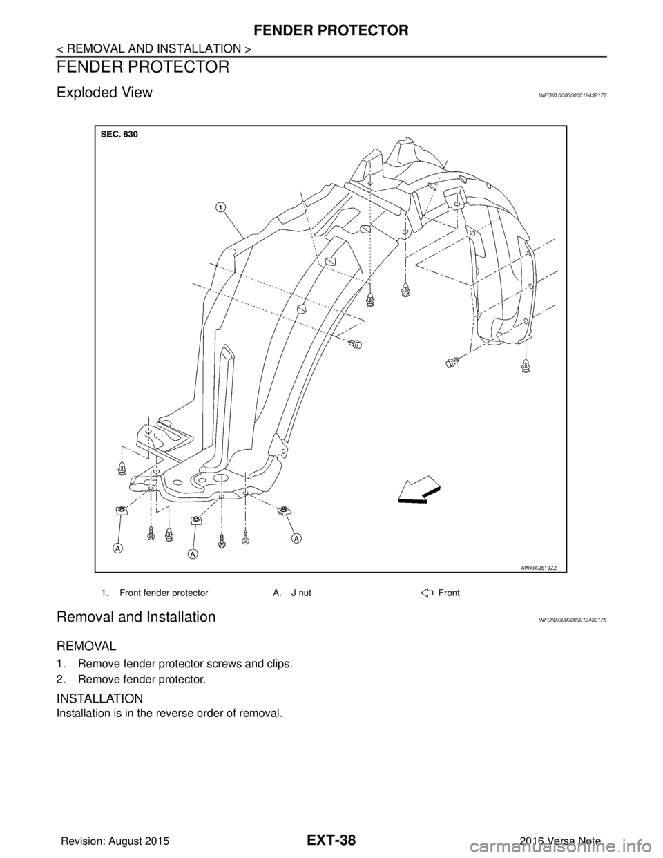
Exploded ViewINFOID:0000000012432177
Removal and InstallationINFOID:0000000012432178
REMOVAL
1. Remove fender protector screws and clips.
2. Remove fender protector.
INSTALLATION
Installation is in the reverse order of removal.
1. Front fender protectorA. J nutFront
AWKIA2513ZZ
Revision: August 2015 2016 Versa Note
cardiagn.com
Page 2051 of 3641
HA-26
< REMOVAL AND INSTALLATION >
COMPRESSOR
REMOVAL AND INSTALLATION
COMPRESSOR
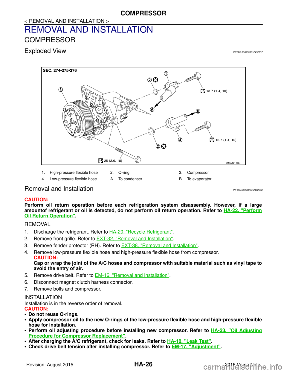
Exploded ViewINFOID:0000000012432007
Removal and InstallationINFOID:0000000012432008
CAUTION:
Perform oil return operation before each refrigeration system disassembly. However, if a large
amountof refrigerant or oil is detected, do not perform oil return operation. Refer to HA-22, "
Perform
Oil Return Operation".
REMOVAL
1. Discharge the refrigerant. Refer to HA-20, "Recycle Refrigerant".
2. Remove front grille. Refer to EXT-32, "
Removal and Installation".
3. Remove fender protector (RH). Refer to EXT-38, "
Removal and Installation".
4. Remove low-pressure flexible hose and high-pressure flexible hose from compressor. CAUTION:
Cap or wrap the joint of the A/C hoses and compr essor with suitable material such as vinyl tape to
avoid the entry of air.
5. Remove drive belt. Refer to EM-16, "
Removal and Installation".
6. Disconnect magnet clutch harness connector.
7. Remove bolts and compressor.
INSTALLATION
Installation is in the reverse order of removal.
CAUTION:
• Do not reuse O-rings.
• Apply compressor oil to the new O-rings of the low-pressure flexible hose an d high-pressure flexible
hose for installation.
• Perform oil adjusting procedure before installing new compressor. Refer to HA-23, "
Oil Adjusting
Procedure for Compressor Replacement".
• After charging the A/C refrig erant, check for leaks. Refer to HA-18, "
Leak Test".
• Check drive belt tension after installing compressor. Refer to EM-17, "
Adjustment".
JMIIA1211GB
1. High-pressure flexible hose 2. O-ring 3. Compressor
4. Low-pressure flexible hose A. To condenser B. To evaporator
Revision: August 2015 2016 Versa Note
cardiagn.com
Page 2328 of 3641
ENGINE MAINTENANCEMA-13
< PERIODIC MAINTENANCE >
C
DE
F
G H
I
J
K L
M B
MA
N
O A
ENGINE MAINTENANCE
DRIVE BELT
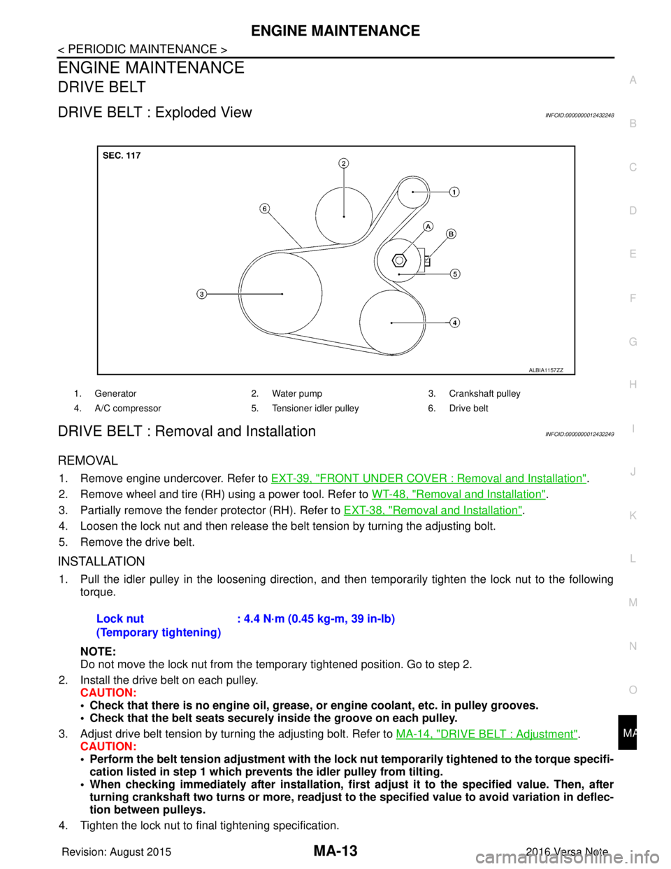
DRIVE BELT : Exploded ViewINFOID:0000000012432248
DRIVE BELT : Removal and InstallationINFOID:0000000012432249
REMOVAL
1. Remove engine undercover. Refer to
EXT-39, "FRONT UNDER COVER : Removal and Installation".
2. Remove wheel and tire (RH) using a power tool. Refer to WT-48, "
Removal and Installation".
3. Partially remove the fender protector (RH). Refer to EXT-38, "
Removal and Installation".
4. Loosen the lock nut and then release the belt tension by turning the adjusting bolt.
5. Remove the drive belt.
INSTALLATION
1. Pull the idler pulley in the loosening direction, and then temporarily tighten the lock nut to the following
torque.
NOTE:
Do not move the lock nut from the temporary tightened position. Go to step 2.
2. Install the drive belt on each pulley. CAUTION:
• Check that there is no engine oil, grease, or engine coolant, etc. in pulley grooves.
• Check that the belt seats securely inside the groove on each pulley.
3. Adjust drive belt tension by turning the adjusting bolt. Refer to MA-14, "
DRIVE BELT : Adjustment".
CAUTION:
• Perform the belt tension adjustment with the lock nut temporarily tightened to the torque specifi-
cation listed in step 1 which preven ts the idler pulley from tilting.
• When checking immediately after in stallation, first adjust it to the specified value. Then, after
turning crankshaft two turns or more, readjust to the specified value to avoid variation in deflec-
tion between pulleys.
4. Tighten the lock nut to final tightening specification.
1. Generator 2. Water pump3. Crankshaft pulley
4. A/C compressor 5. Tensioner idler pulley6. Drive belt
ALBIA1157ZZ
Lock nut
(Temporary tightening): 4.4 N·m (0.45 kg-m, 39 in-lb)
Revision: August 2015
2016 Versa Note
cardiagn.com
Page 2329 of 3641
MA-14
< PERIODIC MAINTENANCE >
ENGINE MAINTENANCE
5. Check that belt tension is within the specification using suitable tool. Refer to EM-116, "Drive Belt".
DRIVE BELT : InspectionINFOID:0000000012432250
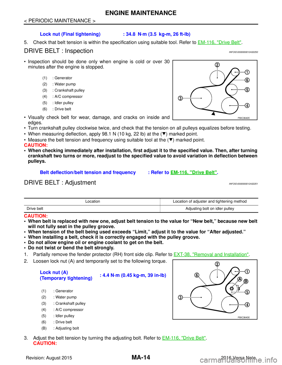
• Inspection should be done only when engine is cold or over 30
minutes after the engine is stopped.
• Visually check belt for wear, damage, and cracks on inside and edges.
• Turn crankshaft pulley clockwise twice, and check that the tension on all pulleys equalizes before testing.
• When measuring deflection, apply 98.1 N (10 kg, 22 lb) at the ( ) marked point.
• Measure the belt tension and frequency using suitable tool at the ( ) marked point.
CAUTION:
• When checking immediately after installation, first ad just it to the specified value. Then, after turning
crankshaft two turns or more, readjust to the speci fied value to avoid variation in deflection between
pulleys.
DRIVE BELT : AdjustmentINFOID:0000000012432251
CAUTION:
• When belt is replaced with new one, adjust belt tension to the value for “New belt,” because new belt will not fully seat in the pulley groove.
• When tension of the belt being used exceeds “Limit,” adjust it to the value for “After adjusted.”
• When installing a belt, check it is co rrectly engaged with the pulley groove.
• Do not allow engine oil or engine coolant to get on the belt.
• Do not twist or bend the belt strongly.
1. Partially remove the fender protector (RH) front side clip. Refer to EXT-38, "
Removal and Installation".
2. Loosen lock nut (A) and temporarily set to the following torque.
3. Adjust the belt tension by turning the adjusting bolt. Refer to EM-116, "
Drive Belt".
CAUTION: Lock nut (Final tightening) :
34.8 N·m (3.5 kg-m, 26 ft-lb)
(1) : Generator
(2) : Water pump
(3) : Crankshaft pulley
(4) : A/C compressor
(5) : Idler pulley
(6) : Drive belt
Belt deflection/belt tension and frequency : Refer to EM-116, "Drive Belt".
PBIC3642E
LocationLocation of adjuster and tightening method
Drive belt Adjusting bolt on idler pulley
Lock nut (A)
(Temporary tightening): 4.4 N·m (0.45 kg-m, 39 in-lb)
(1) : Generator
(2) : Water pump
(3) : Crankshaft pulley
(4) : A/C compressor
(5) : Idler pulley
(6) : Drive belt
(B) : Adjusting bolt
PBIC3643E
Revision: August 2015
2016 Versa Note
cardiagn.com