2016 MITSUBISHI OUTLANDER SPORT break
[x] Cancel search: breakPage 63 of 398
5
Features and controlsBreak-in recommendation
s ..............................................................5-3
Keys ..........................................
.......................................................5-3
Electronic immobilizer (Anti-thef
t starting system) ........................5-4
Keyless entry system (if so equipped) ..............................................5-7Free-hand Advanced Security Transmitter (F.A.S.T.-key) (if so equipped)
.................................................
........................5-12
Door locks .......................
...............................................................5-28
Power door locks ............
...............................................................5-30
Child safety locks for r
ear door .....................................................5-31
Liftgate ......................................
.....................................................5-32
Inside liftgate releas
e .............................................
........................5-33
Theft-alarm system
................................................
........................5-34
Power window control
...........................................
........................5-37
Sunshade (if so equi
pped)..............................................................5-39
Parking brake ..................
...............................................................5-40
Steering wheel height and reach adjustment ..................................5-41Inside rearview mirro
r ...........................................
........................5-42
Outside rearview mirr
ors ...............................................................5-44
Ignition switch ......
.................................................
........................5-46
Starting the engine
.................................................
........................5-47
Manual transaxle (if so equipped) .................................................5-49 Continuously variable transmission
(CVT) (if so equipped).........5-51
Electronically controlled 4WD system (if so equipped)................5-584-wheel drive operation
.........................................
........................5-60
Inspection and maintenance following rough road operation ........5-63 Cautions on the handling of 4-wheel drive vehicles ......................5-63Service brake ..................
...............................................................5-64
Hill start assist .......
.................................................
........................5-65
Brake assist system
...............................................
......................... 5-66
Anti-lock braking syst
em .....................................
......................... 5-67
Electric power steering syst
em (EPS) ........................................... 5-69
Active stability control
(ASC) ....................
................................... 5-70
Cruise control (if so eq
uipped) ...................................................... 5-73
Tire pressure monitoring
system ................................................... 5-77
Rear-view camera (if so eq
uipped) ................................................ 5-81
Instrument cluster
.................................................
......................... 5-83
Multi-information disp
lay ....................................
......................... 5-85
Indicator light, warning light, and information screen disp
lay list ................................................. 5-106
Indicators .................................
.................................................... 5-119
Warning lights ................
.................................................
............. 5-120
Information screen disp
lay ...................................
....................... 5-121
Combination headlights and dimmer switch ............................... 5-123 Headlight leveling switch (if so equipped).................................. 5-129Turn signal lever ..
.................................................
....................... 5-129
Hazard warning flasher
switch .................................................... 5-130
Front fog light switch (if
so equipped) ........................................ 5-130
Wiper and washer swit
ch ......................................
....................... 5-130
Electric rear window def
ogger switch ......................................... 5-136
Horn switch .............................
.................................................... 5-136
Link System (if so equi
pped) .....................
................................. 5-137
Bluetooth
® 2.0 interface (if so
equipped)..................................... 5-137
USB input terminal (if so
equipped) ........................................... 5-160
Sun visors ......................
.................................................
............. 5-163
12 V power outlets .........
.................................................
............. 5-164
HomeLink
® Wireless Control System (if so equipped) ............... 5-165
BK0229600US.bo
ok 1 ページ 2015年10月1日 木曜日 午後2時29分
Page 65 of 398
Break-in recommendations
Features and controls 5-3
5
N00508700330
Advanced automobile manufacturing tech- niques permit you to operate your new vehi-cle without requiring a long break-in period of low-speed driving. However, you can add to the future perfor-mance and economy of your vehicle by observing the following precautions during the first 300 miles (500 km).Drive your vehicle at moderate speeds duringthe break-in period. Avoid revving the engine. Avoid rough driving such as sudden starts, sudden acceleration, prolonged high-speed driving and sudden braking. These would have a detrimental effect on the engine and also cause increased fuel andoil consumption, which could result in malfunction of the engine components. Be particularly careful to avoid full accelera-tion while in low shift position (low gears). Do not overload the vehicle. Stay within the seating capacity. (Refer to “Cargo load precautions” on page 6-10.) Do not use this vehicle for trailer towing.
N00508801660
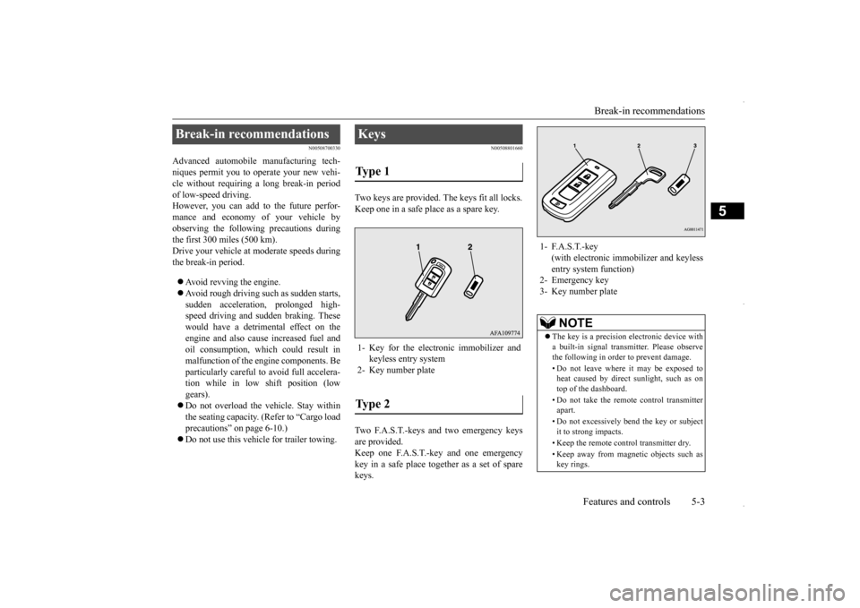
Two keys are provided. The keys fit all locks. Keep one in a safe place as a spare key. Two F.A.S.T.-keys and two emergency keys are provided. Keep one F.A.S.T.-key and one emergencykey in a safe place together as a set of spare keys.
Break-in recommendations
Keys Type 1 1- Key for the electronic immobilizer and
keyless entry system
2- Key number plateType 2
1- F.A.S.T.-key
(with electronic immob
ilizer and keyless
entry system function)
2- Emergency key 3- Key number plate
NOTE
The key is a precision electronic device with a built-in signal transmitter. Please observe the following in order to prevent damage. • Do not leave where it may be exposed to heat caused by direct sunlight, such as ontop of the dashboard. • Do not take the remote control transmitter apart. • Do not excessively bend the key or subject it to strong impacts. • Keep the remote control transmitter dry.• Keep away from magnetic objects such as key rings.
BK0229600US.bo
ok 3 ページ 2015年10月1日 木曜日 午後2時29分
Page 142 of 398
Tire pressure monitoring system 5-80 Features and controls
5
TPMS malfunctions may occur for a variety of reasons, including the installation of replacement or alternate tires or wheels on the vehicle that prevent the TPMS from function-ing properly. Always check the TPMS mal- function telltale after replacing one or more tires or wheels on your vehicle to ensure thatthe replacement or alternate tires and wheels allow the TPMS to continue to function prop- erly.
N00532801524
1. If the tire pressure monitoring systemwarning light illuminates, avoiding hardbraking, sharp steering maneuvers and high speeds. You should stop and adjust the tires to the proper inflation pressure assoon as possible. Adjust the spare tire at the same time. Refer to “Tires” on page 9-14.
2. If the tire pressure monitoring system warning light remains illuminated after you have been driving for about 20 min- utes after you adjust the tire inflation pres-sure, one or more of the tires may have a puncture. Inspect the tire and if it has a puncture, have it repaired by an autho-rized Mitsubishi Motors dealer as soon as possible.
The tire pressure monitoring system may not work normally in the following circum- stances: A wireless facility or device using the same frequency is near the vehicle. Snow or ice is stuck inside the fenders and/or on the wheels. The tire inflation pressure sensor’s battery is dead.
If the warning light/display illu- minates while driving
NOTE
In addition, the warning display is displayed on the information screen in the multi-infor- mation display. When inspecting or adjusting the tire pres- sure, do not apply excessive force to the valve stem to avoid breakage.
After inspecting or adjusting the tire pres- sure, always reinstall the valve cap on the valve stem. Without the valve cap, dirt or moisture could get into the valve, resulting in damage to thetire inflation pressure sensor. Do not use metal valve caps, which may cause a metal reaction, resulting in corrosion and damage of the tire inflation pressure sen- sors. Once adjustments have been made, the warn- ing light will go off after a few minutes ofdriving.WA R N I N G If the warning light/display illuminates while you are driving, avoid hard braking, sharp steering maneuvers and high speeds.Driving with an under-inflated tire adversely affects vehicle performance and can result in an accident.NOTE
CAUTION If a tire has a puncture, replace that tire with the spare tire. Driving on a punctured tire could lead to an accident. The warning light/display may not illuminate immediately in the event of a tire blowout or rapid leak.NOTE
To avoid the risk of damage to the tire infla- tion pressure sensors, have any punctured tire repaired by an authorized Mitsubishi Motors dealer. If the tire repair is not done byan authorized Mitsubishi Motors dealer, it is not covered by your warranty. Do not use an aerosol puncture-repair spray on any tire. Such a spray could damage the tire inflationpressure sensors. Have any puncture repaired by an authorized Mitsubishi Motors dealer.
BK0229600US.bo
ok 80 ページ 2015年10月1日 木曜日 午後2時29分
Page 155 of 398
Multi-information display
Features and controls 5-93
5
Shows the approximate driving range (how many more miles or kilometers you candrive). When this driving range falls below 30 miles (50 km), “---” is displayed. Refuel as soon as possible.
This displays the average speed from the last reset to the present.There are 2 types of mode settings as follows. For details on how to change the average speed display setting, refer to “Changing thefunction settings (With ignition switch or operation mode in ON)” on page 5-99. When the average speed is being dis- played, if you hold down the multi-infor-mation meter switch, these calculations will be reset to zero. When the following operation is per- formed, the mode setting changes auto- matically from manual to auto. [Except for vehicles equipped with the F. A . S . T. - k e y ]Turn the ignition switch to the “ON” posi- tion from the “ACC” or “OFF” position.
[For vehicles equipped with the F.A.S.T.- key] Change the operation mode to ON from ACC or OFF. When the average speed is being dis- played, if you hold down the multi-infor- mation meter switch, these calculations will be reset to zero. When the engine switch or the operation mode is in the following conditions, the average speed display will automatically reset. [Except for vehicles equipped with the F. A . S . T. - k e y ] The ignition switch has been set to the “ACC” or “OFF” position for about 4hours or more. [For vehicles equipped with the F.A.S.T.- key] The operation mode has been set to ACCor OFF for about 4 hours or more.
CAUTION If the engine is overheating, “ ” will blink. In this case, the bar graph is on the red zone. Immediately park the vehicle in a safe place and take the required measures. Refer to“Engine overheating” on page 8-4.
Driving range display
NOTE
The driving range is determined based on the fuel consumption data. This may vary depending on the driving conditions and hab-its. Treat the distance displayed as just a rough guideline. When you refuel, the driving range display is updated. However, if you only add a small amount of fuel, the correct value will not be displayed. Fill to a full tank whenever possible. When your vehicle is stopped on an extremely steep hill, the driving range valuemay, change. This is due to the movement of fuel in the tank and does not indicate any breakdown.
The display setting can be changed to the preferred units (miles or km). Refer to “Changing the function settings (With ignition switch or operation mode in ON)” on page 5-99.
Average speed display Manual reset mode
NOTE
Auto reset mode
NOTE
The average speed display and the average fuel consumption display can be reset sepa- rately in both auto reset mode and manualreset mode.
BK0229600US.bo
ok 93 ページ 2015年10月1日 木曜日 午後2時29分
Page 321 of 398
8
For emergenciesIf the vehicle breaks
down ...............................................................8-2
Jump-starting the engine
........................................
..........................8-2
Engine overheating .........
.................................................................8-4
Jack and tools ..................
.................................................................8-5
How to change a tire
..............................................
..........................8-6
Towing ................................................
...........................................8-12
Operation under adverse driv
ing conditions ..................................8-14
Fuel Pump Shut-off Sy
stem ...........................................................8-15
BK0229600US.bo
ok 1 ページ 2015年10月1日 木曜日 午後2時29分
Page 322 of 398
If the vehicle breaks down 8-2 For emergencies
8
N00836300187
If your vehicle breaks down on the road, move to the shoulder and turn on the hazardwarning flashers. If there is no shoulder, or the shoulder is not safe, drive in the right lane slowly, with the hazard lights flashing, untilyou come to a safe stopping place. Keep the flashers flashing. If the engine stops, there will be no power assist to the steering and brakes, making these difficult to use. The brake booster will not work, so the brakes will not grip well. The brake pedalwill be harder to press than usual. Since there is no power steering assist, the steering wheel will be hard to turn.
Get help from your passengers, bystanders, etc. to push the vehicl
e and move it to a safe
zone.
N00836401824
If the engine cannot be started because the battery is weak or dead, you can start it withthe battery from another vehicle using jumper cables. 1. Take off any metal jewelry such as watch bands or bracelets that might make an accidental electrical contact.2. Position the vehicles close enough together so that the jumper cables can reach, but be sure the vehicles aren’ttouching each other.
3. You could be injured if the vehicles move. Set the parking brake firmly oneach vehicle. Put an automatic transaxle or CVT in “P” (PARK) or a manual trans- axle in “N” (Neutral).4. Turn the ignition switch to the “OFF”position or put the operation mode in OFF. 5. Make sure your battery electrolyte is at the proper level.(Refer to “Battery” on page 9-11.)
If the vehicle breaks down If the engine stops/fails When the engine fails at the intersection
Jump-starting the engine
WA R N I N G When using jumper cables to start a vehi- cle, follow the procedures and be very cau- tious.CAUTION Do not try to start your vehicle by pushing or towing. Vehicles with automatic transaxles cannot be started this way. Also, there is more risk of an accident when a vehicle isbeing pushed or towed.
CAUTION Check the other vehicle. It must have a 12- volt battery. If the other system isn’t 12-volt, both systems can be damaged.WA R N I N G Perform step 4 on both vehicles before- hand. Make sure that the cables or your clothes cannot be ca
ught by the fan or
drive belt. Personal injury could result.NOTE
Turn off all lights, heater, and other electrical loads. This will avoid sparks and help save both batteries.
BK0229600US.bo
ok 2 ページ 2015年10月1日 木曜日 午後2時29分
Page 335 of 398
Fuel Pump Shut-off System
For emergencies 8-15
8
Drive as slow as poss
ible when driving on
bumpy, rutted roads or over potholes.
N00860600028
In the event of a collision causing frontal air-bag deployment, the fuel pump shut-off sys- tem will activate to stop fuel supply to the engine.
CAUTION Do not depress the accelerator pedal rapidly. The vehicle could start moving when it breaks free from the ice, possibly resulting in an accident.
On a bumpy or rutted road
CAUTION Driving on bumpy, rutted roads or over pot- holes can damage the tires and wheels. Wheels with low-profiles tires or under- inflated tires are especially at risk for dam-age.
Fuel Pump Shut-off System
WA R N I N G Before attempting to restart the engine after a collision, always inspect the ground under the vehicle for leaking fuel. If a fuel leak is found or a fuel odor isdetected, do not restart the engine. Mitsubishi Motors recommends that your vehicle be inspected by an authorized Mit- subishi Motors dealer after any collision.
BK0229600US.bo
ok 15 ページ 2015年10月1日 木曜日 午後2時29分
Page 368 of 398
Replacement of light bulbs 9-32 Vehicle care and maintenance
9
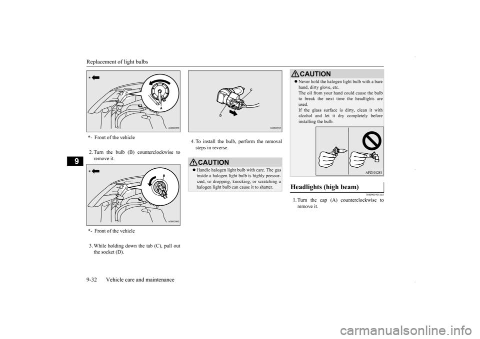
2. Turn the bulb (B) counterclockwise to remove it. 3. While holding down the tab (C), pull out the socket (D).
4. To install the bulb, perform the removal steps in reverse.
N00901901103
1. Turn the cap (A) counterclockwise to remove it.
* - Front of the vehicle * - Front of the vehicle
CAUTIONHandle halogen light bulb with care. The gas inside a halogen light bulb is highly pressur- ized, so dropping, knocking, or scratching a halogen light bulb can cause it to shatter.
Never hold the halogen light bulb with a bare hand, dirty glove, etc. The oil from your hand could cause the bulb to break the next time the headlights are used.If the glass surface is dirty, clean it with alcohol and let it dry completely before installing the bulb.
Headlights (high beam)
CAUTION
BK0229600US.bo
ok 32 ページ 2015年10月1日 木曜日 午後2時29分