2016 MITSUBISHI OUTLANDER SPORT clock
[x] Cancel search: clockPage 319 of 398
General information about your radio
Comfort controls 7-63
7
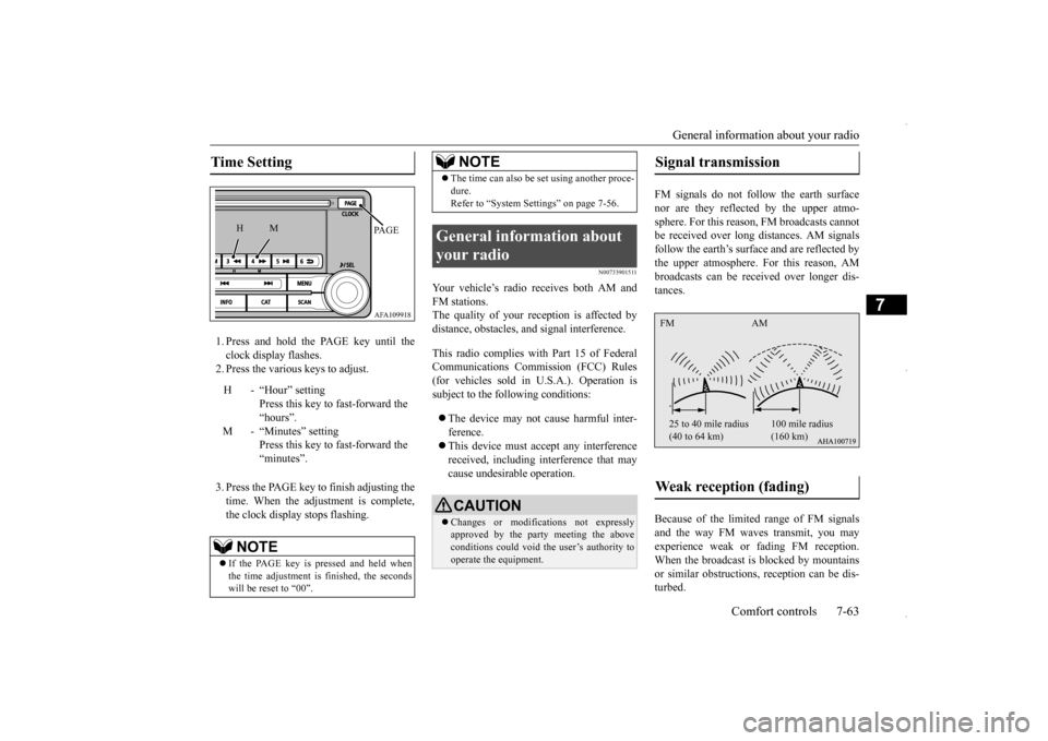
1. Press and hold the PAGE key until the clock display flashes.2. Press the various keys to adjust. 3. Press the PAGE key to finish adjusting the time. When the adjustment is complete, the clock display stops flashing.
N00733901511
Your vehicle’s radio receives both AM and FM stations. The quality of your reception is affected bydistance, obstacles, and signal interference. This radio complies with Part 15 of Federal Communications Commission (FCC) Rules (for vehicles sold in U.S.A.). Operation issubject to the following conditions: The device may not cause harmful inter- ference. This device must accept any interference received, including interference that may cause undesirable operation.
FM signals do not follow the earth surface nor are they reflected by the upper atmo-sphere. For this reason, FM broadcasts cannot be received over long distances. AM signals follow the earth’s surface and are reflected bythe upper atmosphere. For this reason, AM broadcasts can be received over longer dis- tances. Because of the limited range of FM signals and the way FM waves transmit, you may experience weak or fading FM reception.When the broadcast is blocked by mountains or similar obstructions, reception can be dis- turbed.
Time Setting
H - “Hour” setting
Press this key to fast-forward the“hours”.
M - “Minutes” setting
Press this key to fast-forward the “minutes”.
NOTE
If the PAGE key is pressed and held when the time adjustment is finished, the seconds will be reset to “00”.
AFA109918PA G E
M
H
The time can also be set using another proce- dure. Refer to “System Settings” on page 7-56.
General information about your radio
CAUTION Changes or modifications not expressly approved by the party meeting the above conditions could void the user’s authority to operate the equipment.NOTE
Signal transmission Weak reception (fading) FM AM 25 to 40 mile radius (40 to 64 km)
100 mile radius (160 km)
BK0229600US.bo
ok 63 ページ 2015年10月1日 木曜日 午後2時29分
Page 325 of 398
Jack and tools
For emergencies 8-5
8
9. Start the engine, and slowly add coolant, up to the bottom of the filler neck. Useplain water if you have to (and replace it with the right coolant as soon as possible).
10. Replace the radiator cap and tighten it
fully. Check the engine coolant tempera- ture display on the multi-information dis- play. You can start driving again whenthe bar graph for the engine coolant tem- perature display returns to the normal zone.
11. Have the system inspected by your autho-
rized Mitsubishi Motors dealer or a repair facility of your choice.
N00836600337
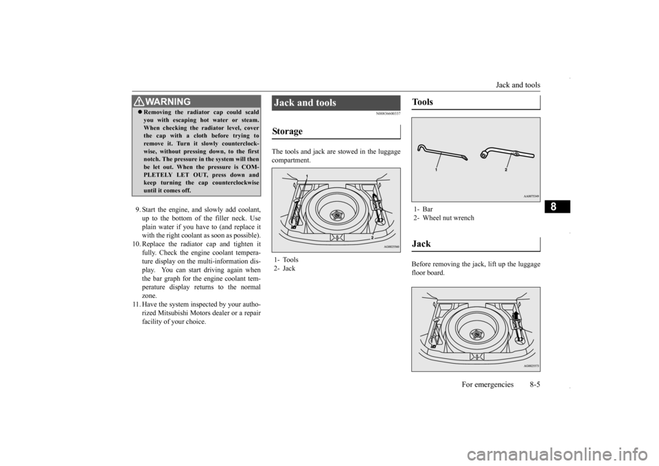
The tools and jack are stowed in the luggagecompartment.
Before removing the jack, lift up the luggage floor board.
WA R N I N G Removing the radiator cap could scald you with escaping hot water or steam. When checking the radiator level, cover the cap with a cloth before trying to remove it. Turn it slowly counterclock-wise, without pressing down, to the first notch. The pressure in the system will then be let out. When the pressure is COM-PLETELY LET OUT, press down and keep turning the cap counterclockwise until it comes off.
Jack and tools Storage 1- Tools 2- Jack
Tools 1- Bar2- Wheel nut wrenchJack
BK0229600US.bo
ok 5 ページ 2015年10月1日 木曜日 午後2時29分
Page 327 of 398
How to change a tire
For emergencies 8-7
8
N00849701355
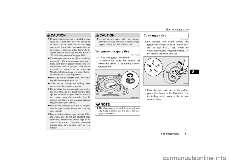
1. Lift up the luggage floor board. 2. To remove the spare tire, remove theinstallation clamp (A) by turning it coun-terclockwise.
N00849801503
1. On vehicles with wheel covers, firstremove the covers (refer to “Wheel cov-ers” on page 8-11). Then, loosen the wheel nuts with the wheel nut wrench. Do not remove the wheel nuts yet. 2. Place the jack under
one of the jacking
points (A) shown in the illustration. Use the jacking point closest to the tire youwish to change.
Driving with an improperly inflated tire can cause an accident. If you have no choice but to drive with an under-inflated tire, keep your speed down and avoid sudden steering or braking, if possible
. Inflate the tire to the
correct pressure as soon as possible. Refer to “Tire inflation pressures” on page 9-18. The compact spare tire should be used only temporarily. While the compact spare tire is being used, the tire pressure monitoring sys-tem will not function properly. Have the tire replaced or repaired at an authorized Mitsubishi Motors dealer or a repair facilityof your choice as soon as possible. Do not go over 50 mph (80 km/h) when driv- ing with the compact spare tire. Avoid sudden starting and braking when driving with the compact spare tire. Do not drive through automatic car washes and over obstacles that could possibly dam- age the underside of your vehicle. Because the compact spare tire is smaller than theoriginal tire, there is less clearance between the ground and your vehicle. Because the compact spare tire is designed only for your vehicle, do not use it on any other vehicle. Do not put the compact spare tire on a differ- ent wheel, and do not put standard tires, snow tires, wheel covers or trim rings on the compact spare wheel. Otherwise, you coulddamage these parts or other parts on your vehicle.CAUTION
Do not use tire chains with your compact spare tire. Using a chain could cause damage to your vehicle and loss of the chains.
To remove the spare tire
NOTE
The clamp cannot be us
ed for a normal size
tire. Store a normal size tire under the lug- gage floor board.CAUTION
To change a tire
BK0229600US.bo
ok 7 ページ 2015年10月1日 木曜日 午後2時29分
Page 330 of 398
How to change a tire 8-10 For emergencies
8
8. Lower the vehicle slowly until the tire touches the ground, by rotating the wheelnut wrench counterclockwise.
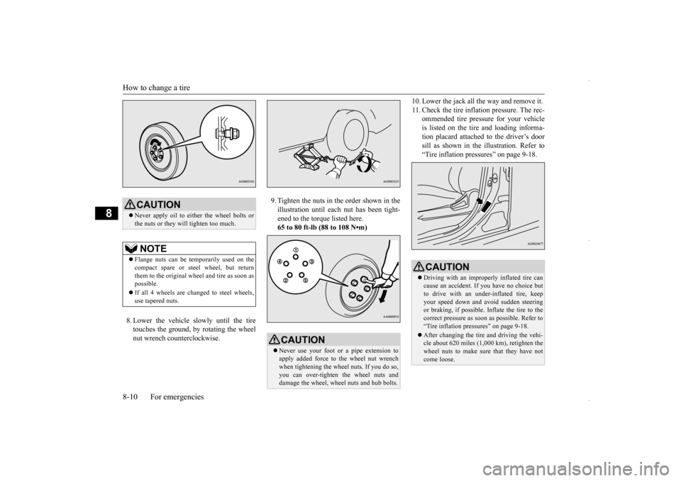
9. Tighten the nuts in the order shown in the illustration until each nut has been tight- ened to the torque listed here.65 to 80 ft-lb (88 to 108 N•m)
10. Lower the jack all the way and remove it. 11. Check the tire inflation pressure. The rec-
ommended tire pressure for your vehicle is listed on the tire and loading informa-tion placard attached to the driver’s door sill as shown in the illustration. Refer to “Tire inflation pressures” on page 9-18.
CAUTION Never apply oil to either the wheel bolts or the nuts or they will tighten too much.NOTE
Flange nuts can be temporarily used on the compact spare or steel wheel, but return them to the original wheel and tire as soon as possible. If all 4 wheels are changed to steel wheels, use tapered nuts.
CAUTION Never use your foot or a pipe extension to apply added force to the wheel nut wrenchwhen tightening the wheel nuts. If you do so, you can over-tighten the wheel nuts and damage the wheel, wheel nuts and hub bolts.
CAUTION Driving with an improperly inflated tire can cause an accident. If
you have no choice but
to drive with an under-inflated tire, keep your speed down and avoid sudden steeringor braking, if possible
. Inflate the tire to the
correct pressure as soon as possible. Refer to “Tire inflation pressures” on page 9-18. After changing the tire and driving the vehi- cle about 620 miles (1,000 km), retighten thewheel nuts to make sure that they have not come loose.
BK0229600US.bo
ok 10 ページ 2015年10月1日 木曜日 午後2時29分
Page 367 of 398
Replacement of light bulbs
Vehicle care and maintenance 9-31
9
N00950401672
* : If so equipped
N00901801144
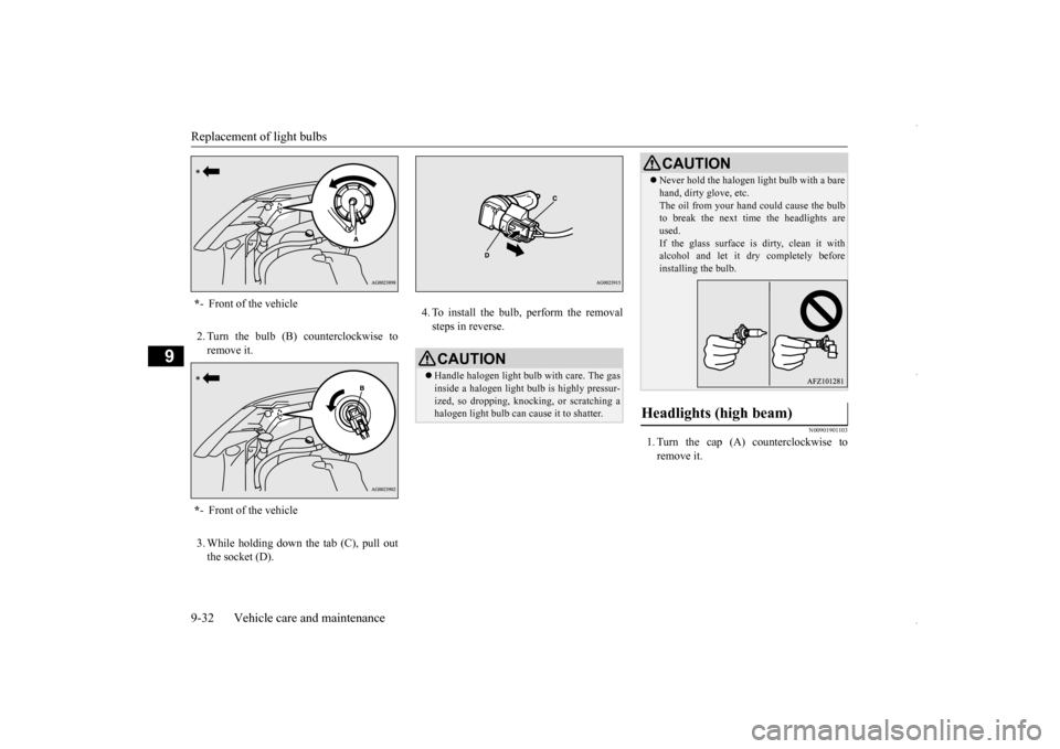
1. Turn the cap (A) counterclockwise to remove it.
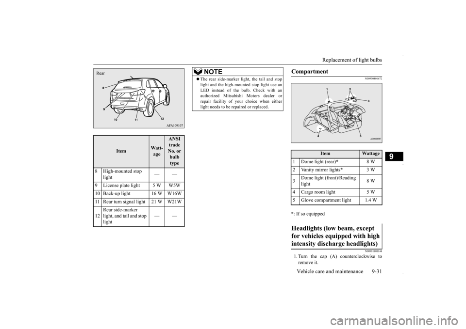
Item
Watt-age
ANSI trade No. or bulb type
8 High-mounted stop
light
——
9 License plate light 5 W W5W 10 Back-up light 16 W W16W11 Rear turn signal light 21 W W21W 12
Rear side-marker light, and tail and stop light
——
Rear
NOTE
The rear side-marker light, the tail and stop light and the high-mounted stop light use an LED instead of the bulb. Check with an authorized Mitsubishi Motors dealer or repair facility of your
choice when either
light needs to be repaired or replaced.
Compartment
Item
Wattage
1 Dome light (rear)
*
8 W
2 Vanity mirror lights
*
3 W
3
Dome light (front)/Reading light
8 W
4 Cargo room light 5 W 5 Glove compartment light 1.4 WHeadlights (low beam, except for vehicles equipped with high intensity discharge headlights)
BK0229600US.bo
ok 31 ページ 2015年10月1日 木曜日 午後2時29分
Page 368 of 398
Replacement of light bulbs 9-32 Vehicle care and maintenance
9
2. Turn the bulb (B) counterclockwise to remove it. 3. While holding down the tab (C), pull out the socket (D).
4. To install the bulb, perform the removal steps in reverse.
N00901901103
1. Turn the cap (A) counterclockwise to remove it.
* - Front of the vehicle * - Front of the vehicle
CAUTIONHandle halogen light bulb with care. The gas inside a halogen light bulb is highly pressur- ized, so dropping, knocking, or scratching a halogen light bulb can cause it to shatter.
Never hold the halogen light bulb with a bare hand, dirty glove, etc. The oil from your hand could cause the bulb to break the next time the headlights are used.If the glass surface is dirty, clean it with alcohol and let it dry completely before installing the bulb.
Headlights (high beam)
CAUTION
BK0229600US.bo
ok 32 ページ 2015年10月1日 木曜日 午後2時29分
Page 369 of 398
Replacement of light bulbs
Vehicle care and maintenance 9-33
9
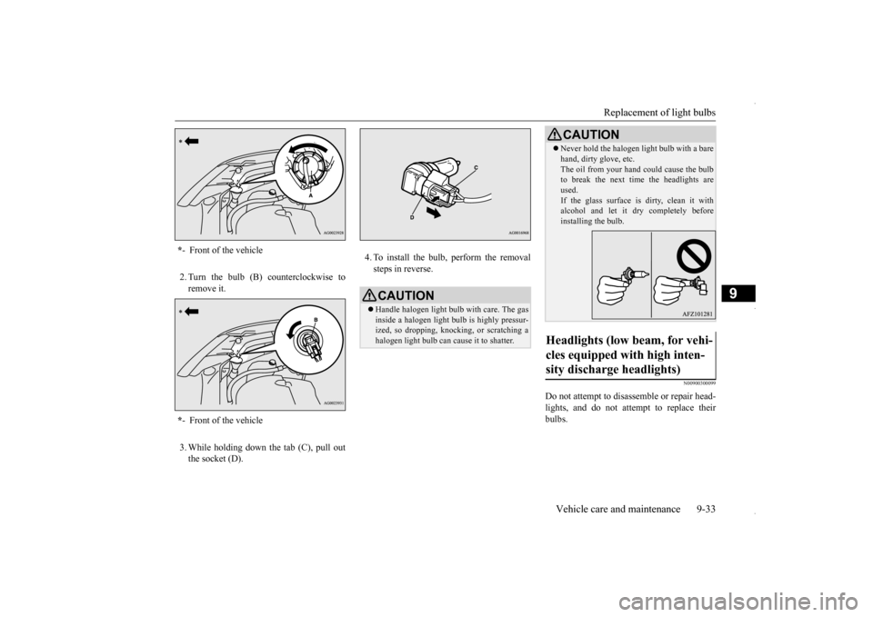
2. Turn the bulb (B) counterclockwise to remove it. 3. While holding down the tab (C), pull out the socket (D).
4. To install the bulb, perform the removal steps in reverse.
N00900300099
Do not attempt to disassemble or repair head- lights, and do not attempt to replace their bulbs.
* - Front of the vehicle * - Front of the vehicle
CAUTIONHandle halogen light bulb with care. The gas inside a halogen light bulb is highly pressur-ized, so dropping, knocking, or scratching a halogen light bulb can cause it to shatter.
Never hold the halogen light bulb with a bare hand, dirty glove, etc. The oil from your hand could cause the bulb to break the next time the headlights are used.If the glass surface is dirty, clean it with alcohol and let it dry completely before installing the bulb.
Headlights (low beam, for vehi- cles equipped with high inten- sity discharge headlights)
CAUTION
BK0229600US.bo
ok 33 ページ 2015年10月1日 木曜日 午後2時29分
Page 370 of 398
Replacement of light bulbs 9-34 Vehicle care and maintenance
9
N00943200121
The alignment of the headlights should be checked by an authorized Mitsubishi Motorsdealer or a repair facility of your choice.
N00917301652
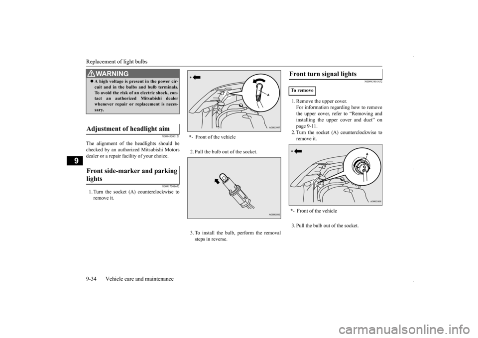
1. Turn the socket (A) counterclockwise to remove it.
2. Pull the bulb out of the socket. 3. To install the bulb, perform the removal steps in reverse.
N00943401452
1. Remove the upper cover.For information regarding how to remove the upper cover, refer to “Removing andinstalling the upper cover and duct” on page 9-11. 2. Turn the socket (A) counterclockwise toremove it. 3. Pull the bulb out of the socket.
WA R N I N G A high voltage is present in the power cir- cuit and in the bulbs and bulb terminals. To avoid the risk of an electric shock, con- tact an authorized Mitsubishi dealer whenever repair or replacement is neces-sary.
Adjustment of headlight aim Front side-marker and parking lights
* - Front of the vehicle
Front turn signal lights To r e m o v e * - Front of the vehicle
BK0229600US.bo
ok 34 ページ 2015年10月1日 木曜日 午後2時29分