2016 MITSUBISHI OUTLANDER SPORT ignition
[x] Cancel search: ignitionPage 50 of 398
Supplemental Restraint System (SRS) - airbag 4-30 Seat and restraint systems
4
To read data recorded by an EDR, special equipment is required, and access to the vehi- cle or the EDR is needed. In addition to the vehicle manufacturer, other parties, such aslaw enforcement, that have the special equip- ment, can read the information if they have access to the vehicle or the EDR.
N00417900177
The driver’s seat position sensor is attachedto the seat rail and provides the airbag controlunit with information on the seat’s fore-aft position. The airbag control unit controls deployment of the driver’s front airbag inaccordance with the information it receives from this sensor. If there is a problem involving the driver’sseat position sensor, the SRS warning light in the instrument panel will come on. Refer to
“SRS warning light/display” on page 4-32.
N00418000322
The passenger’s seat weight sensors are attached to the seat rails and provide the air- bag control unit with information regarding the weight on the front passenger seat. Theairbag control unit controls deployment of the passenger’s front airbag in accordance with the information it receives from this sensor.
The passenger’s front airbag will not deploy in an impact when the weight on the seat is sensed to be less than approximately 66 pounds (30 kg). In this case, the passengerairbag off indicator will come on. Refer to “Passenger’s airbag off indicator” on page 4-31.If there is a problem involving the passenger seat weight sensors, the SRS warning light in the instrument panel will come on. Refer to“SRS warning light/display” on page 4-32.
NOTE
EDR data are recorded by your vehicle only if a non-trivial crash situation occurs; no data are recorded by the EDR under normal driv- ing conditions and no personal data (e.g., name, gender, age, and crash location) arerecorded. However, other parties, such as law enforcement, could combine the EDR data with the type of personally identifyingdata routinely acquired during a crash inves- tigation.
Driver’s seat position sensor
WA R N I N G If the SRS warning light or warning dis- play comes on, have the vehicle inspectedby an authorized Mitsubishi Motors dealer as soon as possible. Please observe the following instructions to ensure that the driver’s seat position sensor can operate correctly.• Adjust the seat to the correct position,and sit well back against the seatback.Refer to “Front seats” on page 4-3.• Do not recline the seatback more thannecessary when driving.• Do not place metallic objects or luggageunder the front seat.
If the vehicle is involved in a severe impact, have the SRS sensors inspected by an authorized Mitsubishi Motors dealer as soon as possible.
Passenger’s seat weight sensors
WA R N I N G If any of the following conditions occur, you should have your vehicle inspected by an authorized Mitsubishi Motors dealer assoon as possible:• The SRS warning light does not initiallycome on when the ignition switch or the operation mode is under the following conditions.• [Except for vehicles equipped with theF. A . S . T. - k e y ]The ignition switch is in the “ON” or “START” position. [Vehicles equipped with the F.A.S.T.-key] The operation mode is in ON.• The SRS warning light does not go outafter several seconds.• The SRS warning light comes on whileyou are driving.
BK0229600US.bo
ok 30 ページ 2015年10月1日 木曜日 午後2時29分
Page 51 of 398
Supplemental Restraint System (SRS) - airbag
Seat and restraint systems 4-31
4
N00418100280
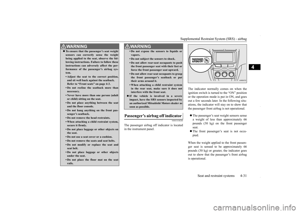
The passenger airbag off indicator is located in the instrument panel.
The indicator normally comes on when the ignition switch is turned to the “ON” position or the operation mode is put in ON, and goesout a few seconds later. In the following situ- ations, the indicator will stay on to show that the passenger front airbag is not operational. The passenger’s seat weight sensors sense a weight of less than approximately 66pounds (30 kg) on the front passenger seat. The front passenger’s seat is not occu- pied.
When the weight applied to the front passen- ger seat is sensed to be approximately 66 pounds (30 kg) or greater, the indicator goesout to show that the passenger’s front airbag is operational.
To ensure that the passenger’s seat weight sensors can correctly sense the weight being applied to the seat, observe the fol- lowing instructions. Failure to follow these instructions can adversely affect the per-formance of the passenger’s airbag sys- tem.• Adjust the seat to the correct position,and sit well back against the seatback. Refer to “Front seats” on page 4-3.• Do not recline the seatback more thannecessary.• Never have more than one person (adultor child) sitting on the seat.• Do not place anything between the seatand the floor console.• Do not hang anything on the front pas-senger’s seatback.• Do not remove the head restraints.• When attaching a child restraint system, secure it firmly.• Do not place luggage or other objects onthe seat.• Do not use a seat cover or a cushion.• Do not remove the seats and seat belts.• Do not modify or replace the seat and seat belt.• Do not place luggage or other objectsunder the seat.• Do not place the floor mat on the seatrails.WA R N I N G
• Do not expose the sensors to liquids or vapors.• Do not subject the sensors to shock.• Do not allow rear-seat occupants to pushthe front passenger seat with their feet or force the front passenger seat upward.• Do not allow rear-seat occupants to graspthe front passenger’s seatback or puttheir arms around it.• When attaching a child restraint systemin the rear seat, make sure it does not interfere with the front seat.
If the vehicle is involved in a severe impact, have the SRS sensors inspected by an authorized Mitsubishi Motors dealer assoon as possible.
Passenger’s airbag off indicator
WA R N I N G
BK0229600US.bo
ok 31 ページ 2015年10月1日 木曜日 午後2時29分
Page 52 of 398
Supplemental Restraint System (SRS) - airbag 4-32 Seat and restraint systems
4
N00408301592
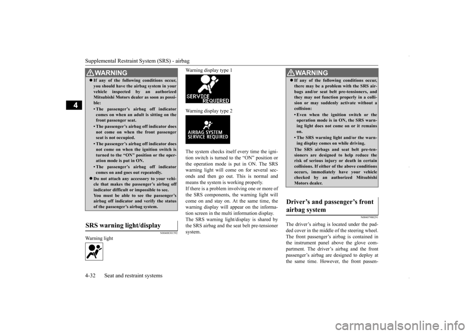
Warning light
Warning display type 1 Warning display type 2The system checks itself every time the igni- tion switch is turned to the “ON” position orthe operation mode is put in ON. The SRS warning light will come on for several sec- onds and then go out. This is normal andmeans the system is working properly. If there is a problem involving one or more of the SRS components, the warning light willcome on and stay on. At the same time, the warning display will appear on the informa- tion screen in the multi information display.The SRS warning light/display is shared bythe SRS airbag and the seat belt pre-tensioner system.
N00407900291
The driver’s airbag is located under the pad- ded cover in the middle of the steering wheel.The front passenger’s airbag is contained in the instrument panel above the glove com- partment. The driver’s airbag and the frontpassenger’s airbag are designed to deploy at the same time. However,
the front passen-
WA R N I N GIf any of the following conditions occur, you should have the airbag system in your vehicle inspected by an authorized Mitsubishi Motors dealer as soon as possi- ble:• The passenger’s airbag off indicatorcomes on when an adult is sitting on thefront passenger seat.• The passenger’s airbag off indicator doesnot come on when the front passenger seat is not occupied.• The passenger’s airbag off indicator doesnot come on when the ignition switch is turned to the “ON” position or the oper-ation mode is put in ON.• The passenger’s airbag off indicatorcomes on and goes out repeatedly.
Do not attach any accessory to your vehi- cle that makes the passenger’s airbag off indicator difficult or impossible to see. You must be able to see the passenger’sairbag off indicator and verify the status of the passenger’s airbag system.
SRS warning light/display
WA R N I N G If any of the following conditions occur, there may be a problem with the SRS air- bags and/or seat belt pre-tensioners, and they may not function properly in a colli- sion or may suddenly activate without acollision:• Even when the ignition switch or theoperation mode is in ON, the SRS warn- ing light does not come on or it remains on.• The SRS warning light and/or the warn-ing display comes on while driving.The SRS airbags and seat belt pre-ten-sioners are designed to help reduce therisk of serious injury or death in certain collisions. If either of the above conditions occurs, immediately have your vehiclechecked by an authorized Mitsubishi Motors dealer.
Driver’s and passenger’s front airbag system
BK0229600US.bo
ok 32 ページ 2015年10月1日 木曜日 午後2時29分
Page 56 of 398

Supplemental Restraint System (SRS) - airbag 4-36 Seat and restraint systems
4
The front airbags and driver’s knee airbag may deploy if the underside of the vehicle suffers a moderate to severe impact (under- carriage impact). Typical situations areshown in the illustration. Because the front airbags and driver’s knee airbag may deploy in certain types of unex- pected impacts, as shown in the illustrations, and these unexpected impacts can move youout of position, it is important to always wear the seat belts properly. When worn properly, seat belts can help maintain your distancefrom the airbags when they begin to inflate. The beginning stage of airbag inflation is the most forceful and can cause serious injury ordeath if you are close to the deploying airbag.The front airbags and driver’s knee airbag MAY DEPLOY when …
WA R N I N G Do not attach anything to the steering wheel’s padded cover, such as trim mate- rial, badges, etc. These could strike and injure an occupant if the airbag inflates. Do not set anything on, or attach anything to, the instrument panel above the glovecompartment. Such items could strike and injure an occupant if the airbag inflates.Collision with an elevat
ed median/island or curb
Vehicle travels over a deep hole/pothole Vehicle drives down a st
eep slope and hits the
ground
WA R N I N G Do not attach accessories to, or put them in front of, the windshield. They could restrict the airbag inflation, or strike andinjure an occupant, when the airbag inflates. Do not attach additional keys or accesso- ries (hard, pointed or heavy objects) to the ignition key. Such objects could preventthe driver’s knee airbag from inflating normally or could be propelled to cause serious injury if the airbag inflates. Do not attach accessories to the lower por- tion of the driver’s side instrument panel.Such objects could prevent the driver’s knee airbag from inflating normally or could be propelled to cause serious injuryif the airbag inflates.
BK0229600US.bo
ok 36 ページ 2015年10月1日 木曜日 午後2時29分
Page 63 of 398
5
Features and controlsBreak-in recommendation
s ..............................................................5-3
Keys ..........................................
.......................................................5-3
Electronic immobilizer (Anti-thef
t starting system) ........................5-4
Keyless entry system (if so equipped) ..............................................5-7Free-hand Advanced Security Transmitter (F.A.S.T.-key) (if so equipped)
.................................................
........................5-12
Door locks .......................
...............................................................5-28
Power door locks ............
...............................................................5-30
Child safety locks for r
ear door .....................................................5-31
Liftgate ......................................
.....................................................5-32
Inside liftgate releas
e .............................................
........................5-33
Theft-alarm system
................................................
........................5-34
Power window control
...........................................
........................5-37
Sunshade (if so equi
pped)..............................................................5-39
Parking brake ..................
...............................................................5-40
Steering wheel height and reach adjustment ..................................5-41Inside rearview mirro
r ...........................................
........................5-42
Outside rearview mirr
ors ...............................................................5-44
Ignition switch ......
.................................................
........................5-46
Starting the engine
.................................................
........................5-47
Manual transaxle (if so equipped) .................................................5-49 Continuously variable transmission
(CVT) (if so equipped).........5-51
Electronically controlled 4WD system (if so equipped)................5-584-wheel drive operation
.........................................
........................5-60
Inspection and maintenance following rough road operation ........5-63 Cautions on the handling of 4-wheel drive vehicles ......................5-63Service brake ..................
...............................................................5-64
Hill start assist .......
.................................................
........................5-65
Brake assist system
...............................................
......................... 5-66
Anti-lock braking syst
em .....................................
......................... 5-67
Electric power steering syst
em (EPS) ........................................... 5-69
Active stability control
(ASC) ....................
................................... 5-70
Cruise control (if so eq
uipped) ...................................................... 5-73
Tire pressure monitoring
system ................................................... 5-77
Rear-view camera (if so eq
uipped) ................................................ 5-81
Instrument cluster
.................................................
......................... 5-83
Multi-information disp
lay ....................................
......................... 5-85
Indicator light, warning light, and information screen disp
lay list ................................................. 5-106
Indicators .................................
.................................................... 5-119
Warning lights ................
.................................................
............. 5-120
Information screen disp
lay ...................................
....................... 5-121
Combination headlights and dimmer switch ............................... 5-123 Headlight leveling switch (if so equipped).................................. 5-129Turn signal lever ..
.................................................
....................... 5-129
Hazard warning flasher
switch .................................................... 5-130
Front fog light switch (if
so equipped) ........................................ 5-130
Wiper and washer swit
ch ......................................
....................... 5-130
Electric rear window def
ogger switch ......................................... 5-136
Horn switch .............................
.................................................... 5-136
Link System (if so equi
pped) .....................
................................. 5-137
Bluetooth
® 2.0 interface (if so
equipped)..................................... 5-137
USB input terminal (if so
equipped) ........................................... 5-160
Sun visors ......................
.................................................
............. 5-163
12 V power outlets .........
.................................................
............. 5-164
HomeLink
® Wireless Control System (if so equipped) ............... 5-165
BK0229600US.bo
ok 1 ページ 2015年10月1日 木曜日 午後2時29分
Page 68 of 398

Electronic immobilizer (Anti-theft starting system) 5-6 Features and controls
5
N00562200126
You can program new keys to the system if you have two valid (already registered) keys and blank immobilizer key (specially cut foryour vehicle at your Mitsubishi Motors dealer) by doing the following: 1. Insert the first valid key into the ignition switch and turn the key to the “ON” posi- tion for 5 seconds.2. Turn the key to the “OFF” position and remove the first key. 3. Within 30 seconds of removing the firstkey, insert the second valid key into the ignition and turn it to the “ON” position. About 10 seconds later, the immobilizerdisplay will start to blink.
4. When the immobilizer display starts blinking, turn the second valid key to the “OFF” position and remove it. Within 30 seconds after doing so, insert a blankimmobilizer key into the ignition switch and turn it to the “ON” position. Perform this operation no more than 30 secondsafter the immobilizer display starts blink- ing. When registration of the ID code is complete, the immobilizer display willcome on for 3 seconds then go off. If anerror occurs, the immobilizer display will go off during the procedure. 5. If you wish to register another key, per- form the process again from step 1.
Customer key programming (Except for vehicles sold in Canada)
NOTE
When the key registration is completed, the immobilizer display will come on within 30seconds of turning the ignition switch to the “ON” position with the blank immobilizer key (specially cut for your vehicle at your Mitsubishi Motors dealer).
NOTE
Perform the operation when the interrupt dis- play screen is not showing. The interrupt dis- play screen may prevent you from seeing the immobilizer display. It is not possible to register a key if: • the immobilizer display goes off during the procedure • the immobilizer display does not come on within 30 seconds after step 4.
The procedure will be terminated automati- cally if: • a period of 30 seconds or longer elapses from the moment when the first key is turned to the “OFF” position to the moment when the second key is turned to the “ON”position • a period of 30 seconds or longer elapses from the moment when the second key is turned to the “OFF” position to the moment when the blank immobilizer key is turnedto the “ON” position
To use the new remote control transmitters, it is necessary to regi
ster the key with both
the electronic immobilizer and keyless entry system.Also refer to “Keyless entry system: Cus- tomer remote control transmitter program- ming” on page 5-9.
BK0229600US.bo
ok 6 ページ 2015年10月1日 木曜日 午後2時29分
Page 70 of 398
Keyless entry system (if so equipped) 5-8 Features and controls
5
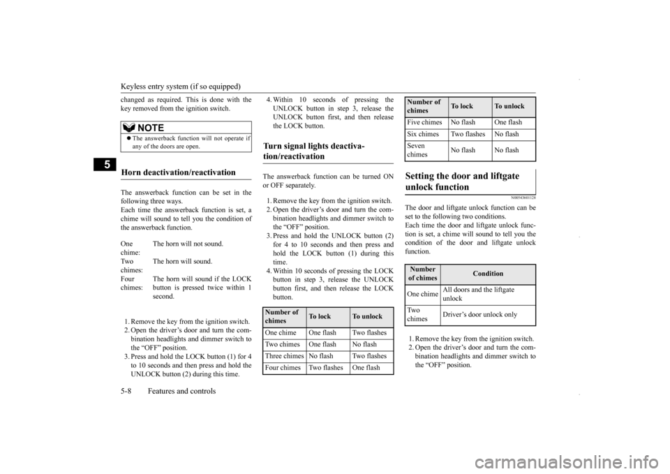
changed as required. This is done with the key removed from the ignition switch. The answerback function can be set in the following three ways. Each time the answerback function is set, achime will sound to tell
you the condition of
the answerback function. 1. Remove the key from the ignition switch. 2. Open the driver’s door and turn the com- bination headlights and dimmer switch tothe “OFF” position. 3. Press and hold the LOCK button (1) for 4 to 10 seconds and then press and hold theUNLOCK button (2) during this time.
4. Within 10 seconds of pressing the UNLOCK button in step 3, release the UNLOCK button first, and then release the LOCK button.
The answerback function can be turned ON or OFF separately. 1. Remove the key from the ignition switch. 2. Open the driver’s door and turn the com- bination headlights and dimmer switch tothe “OFF” position. 3. Press and hold the UNLOCK button (2) for 4 to 10 seconds and then press andhold the LOCK button (1) during this time. 4. Within 10 seconds of pressing the LOCKbutton in step 3, release the UNLOCK button first, and then release the LOCK button.
N00543601128
The door and liftgate unlock function can be set to the following two conditions. Each time the door and liftgate unlock func-tion is set, a chime will sound to tell you the condition of the door and liftgate unlock function. 1. Remove the key from the ignition switch. 2. Open the driver’s door and turn the com- bination headlights and dimmer switch tothe “OFF” position.
NOTE
The answerback function will not operate if any of the doors are open.
Horn deactivation/reactivation
One chime:
The horn will not sound.
Tw o chimes:
The horn will sound.
Four chimes:
The horn will sound if the LOCK button is pressed twice within 1second.
Turn signal lights deactiva- tion/reactivation
Number of chimes
To l o c k
To u n l o c k
One chime One flash Two flashes Two chimes One flash No flashThree chimes No flash Two flashesFour chimes Two flashes One flash
Five chimes No flash One flashSix chimes Two flashes No flashSeven chimes
No flash No flash
Setting the door and liftgate unlock function
Number of chimes
Condition
One chime
All doors and the liftgate unlock
Tw o chimes
Driver’s door unlock only
Number of chimes
To l o c k
To u n l o c k
BK0229600US.bo
ok 8 ページ 2015年10月1日 木曜日 午後2時29分
Page 72 of 398
Keyless entry system (if so equipped) 5-10 Features and controls
5
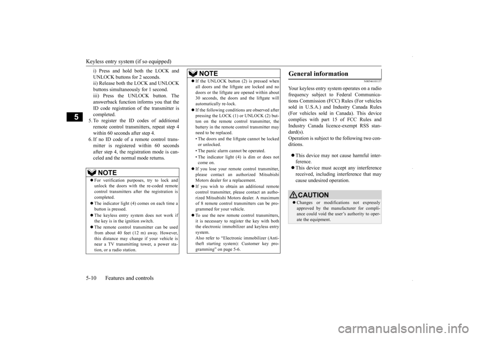
i) Press and hold both the LOCK and UNLOCK buttons for 2 seconds. ii) Release both the LOCK and UNLOCK buttons simultaneously for 1 second.iii) Press the UNLOCK button. The answerback function informs you that the ID code registration of the transmitter iscompleted. 5. To register the ID codes of additional remote control transmitters, repeat step 4within 60 seconds after step 4.6. If no ID code of a remote control trans- mitter is registered within 60 seconds after step 4, the registration mode is can-celed and the normal mode returns.
N00546101137
Your keyless entry system operates on a radiofrequency subject to Federal Communica-tions Commission (FCC) Rules (For vehicles sold in U.S.A.) and Industry Canada Rules (For vehicles sold in Canada). This devicecomplies with part 15 of FCC Rules and Industry Canada licence-exempt RSS stan- dard(s).Operation is subject to the following two con-ditions. This device may not cause harmful inter- ference. This device must accept any interference received, including interference that may cause undesired operation.
NOTE
For verification purposes, try to lock and unlock the doors with the re-coded remote control transmitters after the registration is completed. The indicator light (4) comes on each time a button is pressed. The keyless entry system does not work if the key is in the ignition switch. The remote control transmitter can be used from about 40 feet (12 m) away. However, this distance may change if your vehicle is near a TV transmitting tower, a power sta-tion, or a radio station.
If the UNLOCK button (2) is pressed when all doors and the liftgate are locked and no doors or the liftgate are opened within about 30 seconds, the doors and the liftgate will automatically re-lock. If the following conditions are observed after pressing the LOCK (1) or UNLOCK (2) but-ton on the remote control transmitter, the battery in the remote control transmitter may need to be replaced. • The doors and the liftgate cannot be locked or unlocked. • The panic alarm cannot be operated. • The indicator light (4) is dim or does not come on.
If you lose your remote control transmitter, please contact an authorized Mitsubishi Motors dealer for a replacement. If you wish to obtain an additional remote control transmitter, please contact an autho-rized Mitsubishi Motors dealer. A maximum of 8 remote control transmitters can be pro- grammed for your vehicle. To use the new remote control transmitters, it is necessary to regi
ster the key with both
the electronic immobilizer and keyless entry system. Also refer to “Electr
onic immobilizer (Anti-
theft starting system): Customer key pro- gramming” on page 5-6.NOTE
General information
CAUTION Changes or modifications not expressly approved by the manufacturer for compli-ance could void the user’s authority to oper- ate the equipment.
BK0229600US.bo
ok 10 ページ 2015年10月1日 木曜日 午後2時29分