2016 MITSUBISHI OUTLANDER weight
[x] Cancel search: weightPage 189 of 464
Forward Collision Mitigation System (FCM) (if so equipped)
Features and controls 5-113
5
If the brake pedal is not depressed within 2 seconds after your vehicle has beenstopped by the FCM, a warning buzzerwill sound and the brakes activated by the FCM will automatically be released. Apply the brakes as
necessary to keep
your vehicle stationary.NOTE
When depressing the brake pedal while auto- matic braking is applie
d, the brake pedal will
feel firm. This is normal. Depress the brake pedal harder to apply
greater braking force.
During the automatic braking, operating sounds may be heard. This is normal. WA R N I N G The FCM will not activate and will not provide either warnin
g or braking in cer-
tain situations. Some of these include:• When the selector lever is in the “P”(PARK), the “R” (REVERSE), or the “N” (NEUTRAL) position.• When your vehicle speed is extremelylow, less than approximately 2 mph (2km/h).• When an object other than a vehicle,such as a pedestri
an, is in front.
• When the FCM has detected a problem in the system.WA R N I N G
• When a vehicle sudden
ly cuts in front of
your vehicle.• When the vehicle in fr
ont is moving at a
speed much lower than your vehicle’s speed.
Braking function will not work in the fol- lowing situations.• Your vehicle is driving at approximately19 mph (30 km/h) or faster while thevehicle in front is
stationary or moving
extremely slow.•ASC is OFF. The forward collision warning function and/or the FCM brakin
g function may not
activate in certain situations. Some of these include:• When a vehicle cuts
into your path at a
close distance.• When a vehicle ahead is moving at lowspeed.• When a vehicle ahead is not completelyin your path.• When a vehicle ahead
is towing a trailer.
• When a motorcycle or a bicycle is in front.• When a vehicle ahead is a truck loadedwith freight that protrudes rearward from the cargo bed.• When the height of a vehicle ahead isextremely low or its road clearance isextremely high.WA R N I N G
• When driving on a r
oad with alternating
up and down steep slopes.• When driving on a curve.• When driving on a bumpy or rough road.• When driving in a tunnel.• When the system recognizes driver’s steering, accelerati
ng, braking or gear
shifting actions as
evasive actions to
avoid collision.• When the rear of your vehicle is weigheddown with the weight of passengers and luggage• For up to two minute
s after starting driv-
ing.• In adverse weather conditions, such asrain, snow or fog.• When the surface of th
e sensor is covered
with dirt, snow and ice, etc.• When a vehicle ahea
d or an oncoming
vehicle is splashing wa
ter, snow or dirt.
When the system recognizes driver’s steering or accelerating
actions as evasive
actions to avoid collision, FCM controland alarm functions
may be canceled.
In certain situations,
though there is little
or no risk of a collision, the FCM may activate. Examples include: • When overtaking a vehicle.• When driving on a curve.WA R N I N G
BK0223400US.book 113 ページ 2015年2月13日 金曜日 午後12時15分
Page 194 of 464
Lane Departure Warning System (LDW) (if so equipped) 5-118 Features and controls
5
N00581100023
The LDW, when turned ON, is capable of recognizing the lane in which your vehicle is travelling and issuing
an audible warning
when your vehicle begins to leave that travel lane. When operating, the “LDW” indicator on the multi-information display will be changed to indicator (green). The LDW will not operate, however, and the “LDW” indicator will be appear
ed if any of following
conditions have occurred: The vehicle speed is less than 38 mph (60 km/h). The turn signal lever is being operated or has been operated in
the past 7 seconds.
The hazard warning light is being oper- ated or has been operated in the past 7 seconds. The brake pedal is being depressed.
N00581200037
While the “LDW” indicator in the informa- tion display is lit in gr
een, if your vehicle is
leaving or has left
the lane, a buzzer will
sound intermittently, “LANE DEPARTURE” will appear in the in
formation display and
the indicator will
be flashing in amber.
Operation of the LDW
Lane departure warning
NOTE
The warnings will not continue for more than 3 seconds, even if your
vehicle continues
leaving the lane.WA R N I N G The LDW will not function when no lane marker exists, such as at an intersection or near a toll booth. The LDW may not be ab
le to detect the
lane correctly in the following situations and the LDW may not give warnings ormay give false warnings:• When lane markers are not clearly visi-ble.• When the road surface is shiny.• When old lane markers remain on the road surface.• When the lane markers are double linesor the shape of the lane markers are complicated.
• When driving in an extremely narrowlane.• When the distance between your vehicle and a vehicle in
front is short.
• When driving into the sun light.• When driving on curves.• When driving on bumpy roads.• When driving in construction zones.• When passing through a place where the brightness suddenly
changes, such as at
the entrance to or
exit of a tunnel.
• When the headlights
of an oncoming
vehicle are very bright. • When the rear of your vehicle is weigheddown with the weight of passengers and luggage.• When the headlights
of your vehicle are
not clean or are not properly aimed.• When the front windshield is not clean.• When the front windshield wipers do not clean the windshield properly.CAUTION To maintain proper function of the LDW:• Always keep the windshield and the head- lamps clean.• Do not put anything, su
ch as a sticker, on
the front windshield in front of the LDWcamera • Avoid applying a shock or load to the LDWcamera. WA R N I N G
BK0223400US.book 118 ページ 2015年2月13日 金曜日 午後12時15分
Page 201 of 464
Rear-view camera (if so equipped)
Features and controls 5-125
5
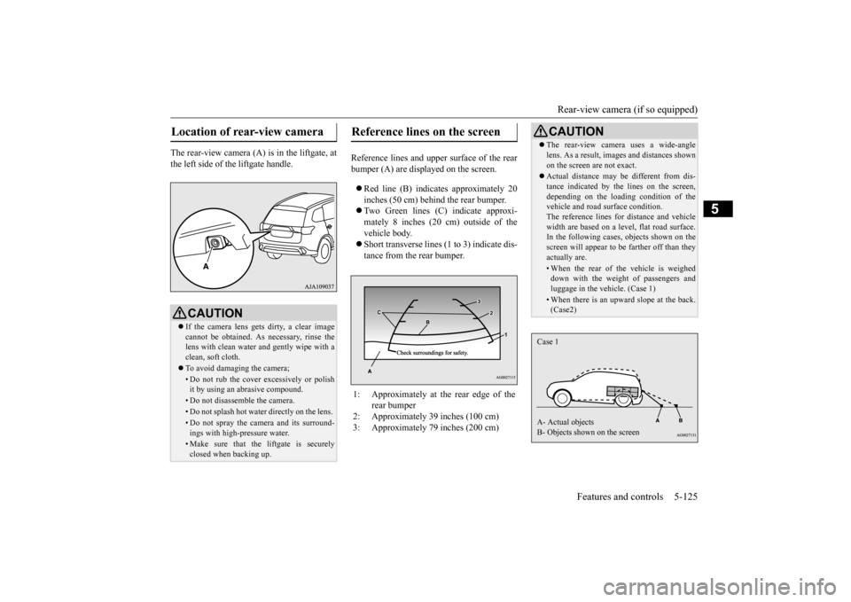
The rear-view camera (A) is in the liftgate, at the left side of
the liftgate handle.
Reference lines and uppe
r surface of the rear
bumper (A) are displayed on the screen. Red line (B) indicates approximately 20 inches (50 cm) behind the rear bumper. Two Green lines (C) indicate approxi- mately 8 inches (20 cm) outside of the vehicle body. Short transverse lines (1
to 3) indicate dis-
tance from the rear bumper.
Location of rear-view camera
CAUTION If the camera lens gets
dirty, a clear image
cannot be obtained. As
necessary, rinse the
lens with clean water a
nd gently wipe with a
clean, soft cloth. To avoid damaging the camera;• Do not rub the cover excessively or polish it by using an abrasive compound. • Do not disassemble the camera.• Do not splash hot wate
r directly on the lens.
• Do not spray the camera and its surround- ings with high-
pressure water.
• Make sure that the liftgate is securely closed when backing up.
Reference lines on the screen
1: Approximately at the rear edge of the
rear bumper
2: Approximately 39 inches (100 cm) 3: Approximately 79 inches (200 cm)
CAUTION The rear-view camera uses a wide-angle lens. As a result, images and distances shownon the screen are not exact. Actual distance may be different from dis- tance indicated by the
lines on the screen,
depending on the loadi
ng condition of the
vehicle and road surface condition. The reference lines for distance and vehiclewidth are based on a level, flat road surface. In the following cases, objects shown on the screen will appear to
be farther off than they
actually are.• When the rear of th
e vehicle is weighed
down with the weight of passengers and luggage in the vehicle. (Case 1)• When there is an upward slope at the back.(Case2)
Case 1 A- Actual objects B- Objects shown on the screen
BK0223400US.book 125 ページ 2015年2月13日 金曜日 午後12時15分
Page 311 of 464
Assist grips
Features and controls 5-235
5
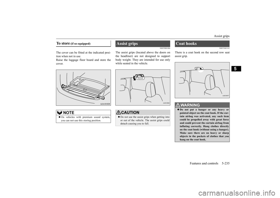
The cover can be fitted at the indicated posi- tion when not in use.Raise the luggage floor
board and store the
cover.
N00559001084
The assist grips (located above the doors onthe headliner) are not designed to support body weight. They are intended for use onlywhile seated in the vehicle.
N00553601163
There is a coat hook on the second row seat assist grip.
To store
(if so equipped)
NOTE
On vehicles with premium sound system, you can not use this storing position.
Assist grips
CAUTION Do not use the assist grips when getting into or out of the vehicle. The assist grips could detach causing you to fall.
Coat hooks
WA R N I N G Do not put a hanger or any heavy or pointed object on the
coat hook. If the cur-
tain airbag was activated, any such item could be propelled away with great force and could prevent the curtain airbag frominflating correctly. Hang clothes directly on the coat hook (without using a hanger). Make sure there ar
e no heavy or sharp
objects in the pocket
s of clothes that you
hang on the coat hook.
BK0223400US.book 235 ページ 2015年2月13日 金曜日 午後12時15分
Page 318 of 464
Parking 6-6 Driving safety
6
N00629601330
When parking on a hill, set the parking brake, and turn the front wheels toward the curb on a downhill, or away from
the curb on an uphill.
If necessary, apply chocks to the wheels. Be sure that the parki
ng brake is firmly set
when parked and that the selector lever is in the “P” (PARK) position. When parking on a hill, it
is important to set
the parking brake before moving the selector lever to the “P” (PARK) position. This pre- vents loading the parking brake against thetransaxle. When this ha
ppens, it is difficult to
move the selector lever out of the “P” (PARK) position. Never leave the engine running while you take a short nap or rest. Also, never leave the engine running in a closed or poorly venti- lated place.
Your front bumper can be damaged if you scrape it over curbs or parking stop blocks.Be careful when traveling up or down steep slopes where your bumper can scrape the road. Always remove the key from the ignition switch and lock all doors and the liftgate when leaving the
vehicle unattended.
Always try to park your vehicle in a well lit area.
Move effort could be required to turn the steering wheel.Refer to “Electric power steering system (EPS)” on page 5-93.
N00629900352
It is very important to know how much weight your vehicle can carry. This weight iscalled the vehicle ca
pacity weight and
includes the weight of
all occupants, cargo
(including the roof load), non-factory-installed options, and the tongue weight of the trailer, if any, being towed. The tire and loading information placard located on thedriver’s door sill of
your vehicle will show
how much weight it may properly carry. It is important to familiarize yourself with the following terms before
loading your vehicle:
Parking Parking on a hill Parking with the engine run- ning
WA R N I N G Leaving the engine ru
nning risks injury or
death from accidentally moving the selec-tor lever or the accumulation of toxicexhaust fumes in the passenger compart- ment.
Where you park
WA R N I N G Do not park your vehicle in areas where combustible materials
such as dry grass or
leaves can come in contact with a hotexhaust, since a fire could occur.
When leaving the vehicle
Do not keep the steering wheel fully turned for a long time Loading information
WA R N I N G Never overload your ve
hicle. Overloading
can damage your vehicle, adversely affectvehicle performance, including handling and braking, cause tire failure, and result in an accident.
BK0223400US.book 6 ページ 2015年2月13日 金曜日 午後12時15分
Page 319 of 464
Loading information Driving safety 6-7
6
Vehicle maximum load on the tire: load on an individual tire that is determined bydistributing to each axle its share of the maximum loaded vehicle weight and dividing by two. Vehicle normal load on the tire: load on an individual tire that is determined by dis- tributing to each axle its share of the curbweight, accessory weight, and normal occupant weight and dividing by two. Maximum loaded vehicle weight: the sum of - (a) Curb weight;(b) Accessory weight; (c) Vehicle capacity weight; and (d) Production options weight. Curb weight: the weight of a motor vehi- cle with standard e
quipment including the
maximum capacity of fuel, oil, and cool-ant. Accessory weight: the combined weight (in excess of those
standard items which
may be replaced) of automatic transmis- sion, power steering, power brakes, power windows, power seats, radio, and heater,to the extent that these items are available as factory- installed equipment (whether installed or not). Vehicle capacity weight: the rated cargo and luggage load plus 150 lbs (68 kg) * times the vehicle’s
designated seating
capacity.
Production options weight: the combined weight of those installed regular produc-tion options weighing over 5 lbs (2.3 kg) in excess of those standard items which they replace, not prev
iously considered in
curb weight or accessory weight, includ- ing heavy duty brakes,
ride levelers, roof
rack, heavy duty battery, and special trim. Normal occupant weight: 150 lbs (68 kg) * times the number of
specified occupants
(3 in the case of your vehicle) Occupant distribution:
Occupant distribu-
tion within the passenger compartment (Inyour vehicle the distribution is 2 in front, 1 in second row seat)
N00630101407
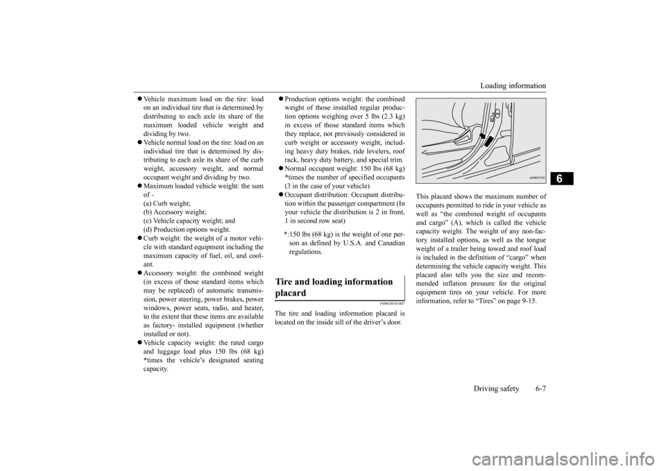
The tire and loading information placard is located on the inside sill of the driver’s door.
This placard shows the maximum number of occupants permitted to
ride in your vehicle as
well as “the combined
weight of occupants
and cargo” (A), which
is called the vehicle
capacity weight. The weight of any non-fac-tory installed options, as well as the tongue weight of a trailer being towed and roof load is included in the defi
nition of “cargo” when
determining the vehicle
capacity weight. This
placard also tells you the size and recom- mended inflation pressure for the originalequipment tires on your vehicle. For more information, refer to
“Tires” on page 9-15.
* :150 lbs (68 kg) is th
e weight of one per-
son as defined by U.S.A. and Canadian regulations.
Tire and loading information placard
BK0223400US.book 7 ページ 2015年2月13日 金曜日 午後12時15分
Page 320 of 464
Loading information 6-8 Driving safety
6
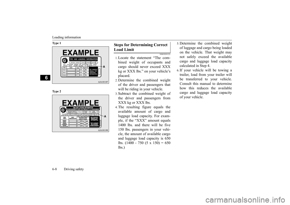
Ty p e 1 Ty p e 2
N00630201222
1.Locate the statement “The com- bined weight of occupants and cargo should never exceed XXX kg or XXX lbs.” on your vehicle’splacard.2.Determine the combined weightof the driver and passengers thatwill be riding in your vehicle.3.Subtract the combined weight ofthe driver and passengers fromXXX kg or XXX lbs.4.The resulting figure equals theavailable amount of cargo andluggage load capacity. For exam- ple, if the “XXX” amount equals 1400 lbs. and there will be five150 lbs. passengers in your vehi- cle, the amount of available cargo and luggage load
capacity is 650
lbs. (1400 - 750 (5 x 150) = 650lbs.)
5.Determine the combined weightof luggage and cargo being loaded on the vehicle. That weight may not safely exceed the availablecargo and luggage load capacity calculated in Step 4.6.If your vehicle will be towing a trailer, load from your trailer will be transferred to your vehicle. Consult this manual to determinehow this reduces the available cargo and luggage load capacity of your vehicle.
Steps for Determining Correct Load Limit
BK0223400US.book 8 ページ 2015年2月13日 金曜日 午後12時15分
Page 321 of 464
Loading information Driving safety 6-9
6
NOTE
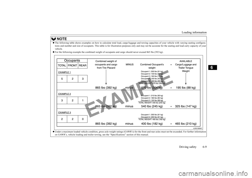
The following table shows examples on how to
calculate tota
l load, cargo/luggage and towing capa
cities of your vehicle with var
ying seating configura-
tions and number and size of occ
upants. This table is for illu
stration purposes only and may not
be accurate for the seating an
d load carry capacity of your
vehicle. For the following example the combined weight of oc
cupants and cargo should ne
ver exceed 865 lbs (392 kg).
Under a maximum loaded vehicle c
ondition, gross axle weight ratings (GAWR’s) for
the front and rear axles must not be exceeded.
For further information
on GAWR’s, vehicle loading and tr
ailer towing, see the “Specifica
tions” section of this manual.
BK0223400US.book 9 ページ 2015年2月13日 金曜日 午後12時15分