2016 MERCEDES-BENZ SL ROADSTER fuse
[x] Cancel search: fusePage 14 of 333
Frequencies
Garage door opener ...................... .272
Mobile phone ................................. 320
Two-way radio ................................ 320
Front-passenger front airbag deac-
tivation
Display message ............................ 226
Front-passenger front airbag deac-
tivation system
Operation ......................................... 46
Problems ......................................... 50
System self-test ............................... 48
Front-passenger seat
Adjusting from the driver's seat ..... 103
Fuel
Additives ........................................ 324
Consumption statistics .................. 202
Displaying the current consump-
tion ................................................ 202
Displaying the range ..................... .202
Driving tips ................................... .156
Fuel gauge ....................................... 32
Grade (petrol) ................................ 323
Important safety notes .................. 322
Notes for Mercedes‑AMG vehi-
cles ................................................ 324
Problem (malfunction) ................... 153
Refuelling ....................................... 151
Tank content/reserve fuel ............. 323
Fuel filler flap
Opening ......................................... 152
Fuel level
Calling up the range (on-board
computer) ...................................... 202
Gauge .............................................. 32
Fuel tank
Capacity ........................................ 323
Problem (malfunction) ................... 153
Fuse allocation chart (vehicle tool
kit) ...................................................... 288
Fuses
Allocation chart ............................ .301
Before changing ............................ .301
Dashboard fuse box ....................... 301
Fuse box in the engine compart-
ment .............................................. 302
Fuse box in the rear compartment .. 302
Important safety notes .................. 301 G
Garage door opener Clearing the memory ..................... 271
Frequencies ................................... 272
General notes ................................ 269
Important safety notes .................. 270
Opening/closing the garage door .. 271
Problems when programming ....... .271
Programming (button in the rear-
view mirror) ................................... 270
Synchronising the rolling code ....... 271
Gear indicator (on-board com-
puter, Mercedes-AMG vehicles) ....... 213
Gearshift paddles
see Steering wheel gearshift paddles
Gearshift program
SETUP (on-board computer) .......... 213
Genuine Mercedes-Benz parts ........... 23
Glove compartment .......................... 262
Google™ Local Search
See also Digital Owner's Manual ... 253 H
HANDS-FREE ACCESS .......................... 87
Hazard warning lamps
Display message ............................ 242
Switching on/off ........................... 115
Head level heating (AIRSCARF) ........105
Head restraints
Adjusting ....................................... 103
see NECK-PRO head restraints
Headbag
Display message ............................ 225
Operation ......................................... 46
Headlamp flasher .............................. 115
Headlamps
see Automatic headlamp mode
Heating
see Climate control
High-pressure cleaners .................... 283
Hill start assist .................................. 135
HOLD function
Activating ....................................... 173
Activation conditions ..................... 173
Deactivating ................................... 173
Display message ............................ 232 Index
11
Page 76 of 333
In order to maintain the appropriate distance to
the vehicle in front and thus prevent a collision,
you must apply the brakes yourself. G
WARNING
Active Brake Assist with cross-traffic function does not react:
R to small people, e.g. children
R to animals
R to oncoming vehicles
R to crossing traffic
R when cornering
As a result, Active Brake Assist with cross-
traffic function may not intervene in all critical situations. There is a risk of an accident.
Always pay careful attention to the traffic sit- uation and be ready to brake.
In the event of snowfall or heavy rain, detection can be impaired.
Detection by the radar sensor system is also
impaired in the event of:
R dirt on the sensors or obscured sensors
R interference by other radar sources
R strong radar reflections, for example, in multi-
storey car parks
R a narrow vehicle travelling in front, e.g. a
motorcycle
R a vehicle travelling in front on a different line
Detection by the camera system is also impaired in the event of:
R dirt on the camera or if the camera is covered
R glare on the camera system, e.g. from the sun
being low in the sky
R darkness
R if:
- pedestrians move quickly, e.g. into the path
of the vehicle
- the camera system no longer detects a
pedestrian as a person due to special cloth-
ing or other objects
- a pedestrian is concealed by other objects
- the typical outline of a person is not distin-
guishable from the background
Following damage to the front end of the vehicle, have the radar sensor settings and operation
checked at a qualified specialist workshop. This
also applies to collisions at slow speeds where there is no visible damage to the front of the
vehicle.
Following damage to the windscreen, have the
configuration and operation of the camera sys-
tem checked at a qualified specialist workshop.
Function X
To activate or deactivate: activate or deac-
tivate Active Brake Assist with cross-traffic
function using the on-board computer
(Y page 207).
When Active Brake Assist with cross-traffic
function is deactivated, the æsymbol
appears in the assistance graphic display of
the multifunction display.
This function will issue a warning if:
R at a speed of approximately 30 km/h or
higher, the distance maintained to the vehicle
travelling in front is insufficient for several
seconds.
The · distance warning lamp then lights
up in the instrument cluster.
R at a speed of approximately 7 km/h or higher,
you rapidly approach a vehicle in front.
An intermittent warning tone will then sound
and the ·distance warning lamp will light
up in the instrument cluster.
X Brake immediately to defuse the situation.
or
X Take evasive action provided it is safe to do
so.
Active Brake Assist with cross-traffic function
can also brake the vehicle automatically under
the following conditions: R the driver and front passenger have their seat
belts fastened
and
R the vehicle speed is between approximately
7 km/h and 200 km/h
Up to a speed of approximately 70 km/h, Active
Brake Assist with cross-traffic function may
react to:
R stationary objects in the path of your vehicle,
e.g. stopped or parked vehicles
R pedestrians in the path of your vehicle
i If there is an increased risk of a collision,
preventive passenger protection measures
(PRE-SAFE ®
) are triggered (Y page 53). Driving safety systems
73Safety Z
Page 126 of 333
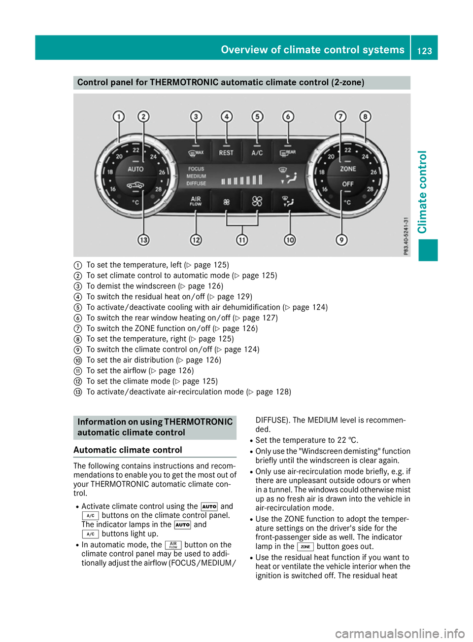
Control panel for THERMOTRONIC automatic climate control (2-zone)
:
To set the temperature, left (Y page 125)
; To set climate control to automatic mode (Y page 125)
= To demist the windscreen (Y page 126)
? To switch the residual heat on/off (Y page 129)
A To activate/deactivate cooling with air dehumidification (Y page 124)
B To switch the rear window heating on/off (Y page 127)
C To switch the ZONE function on/off (Y page 126)
D To set the temperature, right (Y page 125)
E To switch the climate control on/off (Y page 124)
F To set the air distribution (Y page 126)
G To set the airflow (Y page 126)
H To set the climate mode (Y page 125)
I To activate/deactivate air-recirculation mode (Y page 128)Information on using THERMOTRONIC
automatic climate control
Automatic climate control The following contains instructions and recom-
mendations to enable you to get the most out of
your THERMOTRONIC automatic climate con-
trol.
R Activate climate control using the Ãand
¿ buttons on the climate control panel.
The indicator lamps in the Ãand
¿ buttons light up.
R In automatic mode, the ñbutton on the
climate control panel may be used to addi-
tionally adjust the airflow (FOCUS/MEDIUM/ DIFFUSE). The MEDIUM level is recommen-
ded.
R Set the temperature to 22 †.
R Only use the "Windscreen demisting" function
briefly until the windscreen is clear again.
R Only use air-recirculation mode briefly, e.g. if
there are unpleasant outside odours or when
in a tunnel. The windows could otherwise mist
up as no fresh air is drawn into the vehicle in air-recirculation mode.
R Use the ZONE function to adopt the temper-
ature settings on the driver's side for the
front-passenger side as well. The indicator
lamp in the ábutton goes out.
R Use the residual heat function if you want to
heat or ventilate the vehicle interior when the
ignition is switched off. The residual heat Overview of climate control systems
123Climate control
Page 128 of 333
Problems with the "Cooling with air dehumidification" function
Problem
Possible causes/consequences and
M
MSolutions The indicator lamp in the
¿ button flashes
three times or remains
off. The cooling with air
dehumidification func-
tion cannot be activated. The cooling with air dehumidification function has been deactivated
due to a malfunction.
X Consult a qualified specialist workshop. Setting climate control to automatic
mode
General notes In automatic mode, the set temperature is main-
tained automatically at a constant level. The
system automatically regulates the temperature of the dispensed air, the airflow and the air dis- tribution.
The automatic mode functions optimally when
the "Cooling with air dehumidification" function is activated. If desired, cooling with air dehu-
midification can be deactivated.
If you deactivate the "Cooling with air dehumid-
ification" function, the air inside the vehicle will not be cooled. The air inside the vehicle will also
not be dehumidified. The windows can mist up
more quickly. Therefore, deactivate the "Cooling
with air dehumidification" function only briefly.
Automatic control X
Turn the key to position 2in the ignition lock
(Y page 132).
X Set the desired temperature.
X To activate: press theÃbutton.
The indicator lamp in the Ãbutton lights
up. Automatic air distribution and airflow are
activated.
i When automatic mode is enabled, the cli-
mate mode can be selected (Y page 125).
X To switch to manual mode: press the_
button.
or X Press the IorK button.
The indicator lamp in the Ãbutton goes
out. Setting the climate mode
In automatic mode you can select the following
climate modes:
FOCUS high airflow, slightly cooler setting
MEDIUM medium airflow, standard setting
DIFFUSE low airflow, slightly warmer and draught-free setting
X Turn the key to position 2in the ignition lock
(Y page 132).
X Press the Ãbutton.
X Press the ñbutton repeatedly until the
desired climate mode appears in the display. Setting the temperature
Switching on/off Different temperatures can be set for the driv-
er's and front-passenger sides.
X Turn the key to position 2in the ignition lock
(Y page 132).
X Turn control :or; anti-clockwise or clock-
wise.
Only change the temperature setting in small
increments. Start at 22 †.
i If you turn controls
:and ;anti-clock-
wise to the lowest temperature setting, air-
recirculation mode may switch on automati-
cally, depending on the outside temperature. Operating the climate control system
125Climate control
Page 175 of 333
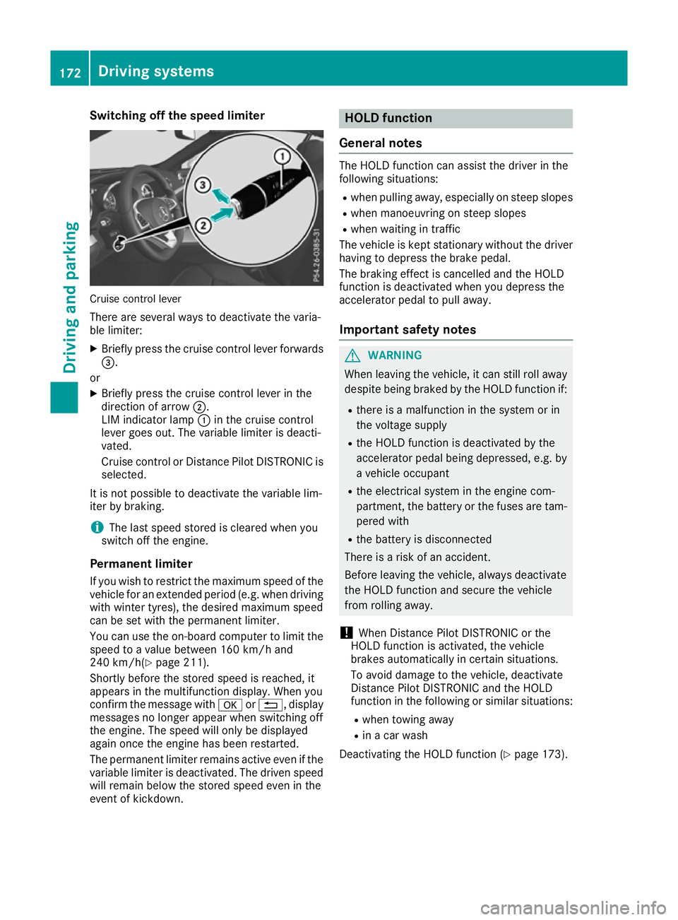
Switching off the speed limiter
Cruise control lever
There are several ways to deactivate the varia-
ble limiter:
X Briefly press the cruise control lever forwards
=.
or
X Briefly press the cruise control lever in the
direction of arrow ;.
LIM indicator lamp :in the cruise control
lever goes out. The variable limiter is deacti-
vated.
Cruise control or Distance Pilot DISTRONIC is
selected.
It is not possible to deactivate the variable lim-
iter by braking.
i The last speed stored is cleared when you
switch off the engine.
Permanent limiter If you wish to restrict the maximum speed of the
vehicle for an extended period (e.g. when driving
with winter tyres), the desired maximum speed
can be set with the permanent limiter.
You can use the on-board computer to limit the speed to a value between 160 km/h and
240 km/h(Y page 211).
Shortly before the stored speed is reached, it
appears in the multifunction display. When you
confirm the message with aor%, display
messages no longer appear when switching off
the engine. The speed will only be displayed
again once the engine has been restarted.
The permanent limiter remains active even if the variable limiter is deactivated. The driven speed
will remain below the stored speed even in the
event of kickdown. HOLD function
General notes The HOLD function can assist the driver in the
following situations:
R when pulling away, especially on steep slopes
R when manoeuvring on steep slopes
R when waiting in traffic
The vehicle is kept stationary without the driver
having to depress the brake pedal.
The braking effect is cancelled and the HOLD
function is deactivated when you depress the
accelerator pedal to pull away.
Important safety notes G
WARNING
When leaving the vehicle, it can still roll away despite being braked by the HOLD function if:
R there is a malfunction in the system or in
the voltage supply
R the HOLD function is deactivated by the
accelerator pedal being depressed, e.g. by
a vehicle occupant
R the electrical system in the engine com-
partment, the battery or the fuses are tam-
pered with
R the battery is disconnected
There is a risk of an accident.
Before leaving the vehicle, always deactivate
the HOLD function and secure the vehicle
from rolling away.
! When Distance Pilot DISTRONIC or the
HOLD function is activated, the vehicle
brakes automatically in certain situations.
To avoid damage to the vehicle, deactivate
Distance Pilot DISTRONIC and the HOLD
function in the following or similar situations:
R when towing away
R in a car wash
Deactivating the HOLD function (Y page 173).172
Driving systemsDriving and parking
Page 291 of 333
X
Lift and swing out bracket =from the side on
which locking button ?is located.
X Take fire extinguisher ;out of the roller box.
X To insert: insert fire extinguisher ;into the
roller box.
X Insert bracket =into the roller box on the
side opposite locking button ?.
X Then, insert bracket =completely.
X Slide locking button ?in the opposite direc-
tion to the arrow.
X Check whether bracket =is properly
engaged.
X Close cover :.
Have the fire extinguisher refilled after each use and checked every one or two years. It may oth-
erwise fail in an emergency. Vehicle tool kit
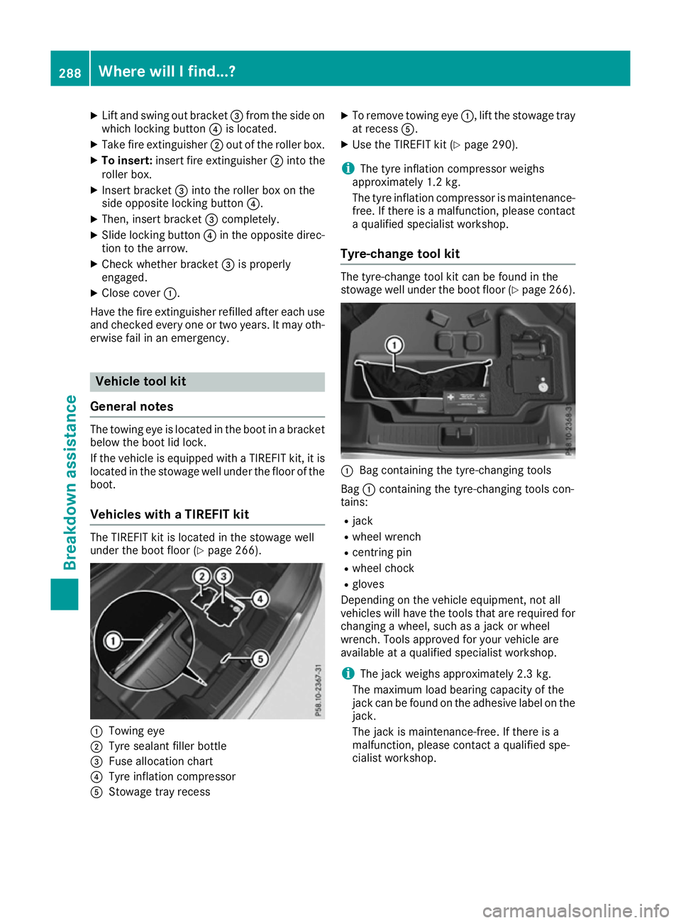
General notes The towing eye is located in the boot in a bracket
below the boot lid lock.
If the vehicle is equipped with a TIREFIT kit, it is located in the stowage well under the floor of the
boot.
Vehicles with a TIREFIT kit The TIREFIT kit is located in the stowage well
under the boot floor (Y page 266).:
Towing eye
; Tyre sealant filler bottle
= Fuse allocation chart
? Tyre inflation compressor
A Stowage tray recess X
To remove towing eye :, lift the stowage tray
at recess A.
X Use the TIREFIT kit (Y page 290).
i The tyre inflation compressor weighs
approximately 1.2 kg.
The tyre inflation compressor is maintenance-
free. If there is a malfunction, please contact a qualified specialist workshop.
Tyre-change tool kit The tyre-change tool kit can be found in the
stowage well under the boot floor (Y
page 266). :
Bag containing the tyre-changing tools
Bag :containing the tyre-changing tools con-
tains:
R jack
R wheel wrench
R centring pin
R wheel chock
R gloves
Depending on the vehicle equipment, not all
vehicles will have the tools that are required for
changing a wheel, such as a jack or wheel
wrench. Tools approved for your vehicle are
available at a qualified specialist workshop.
i The jack weighs approximately 2.3 kg.
The maximum load bearing capacity of the
jack can be found on the adhesive label on the jack.
The jack is maintenance-free. If there is a
malfunction, please contact a qualified spe-
cialist workshop. 288
Where will I find...?Breakdown assistance
Page 304 of 333
Tow-starting (emergency engine
starting)
! Do not tow-start vehicles with automatic
transmission. You could otherwise damage
the automatic transmission.
You can find information on "Jump-starting"
under (Y page 296). Electrical fuses
Important safety notes
G
WARNING
If you manipulate, bridge or replace a faulty
fuse with a fuse of a higher amperage, the
electric cables could be overloaded. This may result in a fire. There is a risk of an accident
and injury.
Always replace faulty fuses with specified new fuses of the correct amperage.
Blown fuses must be replaced with fuses of the same rating, which you can recognise by the
colour and fuse rating. The fuse ratings are listed
in the fuse allocation chart.
The fuse allocation chart is located in the vehicle tool kit in the stowage compartment under the
boot floor (Y page 288).
If the newly inserted fuse also blows, have the
cause traced and rectified at a qualified special- ist workshop, e.g. a Mercedes-Benz Service
Centre.
! Only use fuses that have been approved for
Mercedes-Benz vehicles and which have the
correct fuse rating for the system concerned.
Otherwise, components or systems could be
damaged.
! Make sure that no moisture can enter the
fuse box when the cover is open.
! When closing the cover, make sure that it is
lying correctly on the fuse box. Moisture seep-
ing in or dirt could otherwise impair the oper- ation of the fuses.
The fuses in your vehicle disconnect faulty cir-
cuits. If a fuse blows, all the components on the
circuit and their functions will fail. Before replacing a fuse
X Switch off the engine.
X Switch off all electrical consumers.
X Make sure that the ignition is switched off
(Y page 132).
or X When using the key, turn the key to position 0
in the ignition lock and remove it
(Y page 132).
X Safeguard the vehicle against rolling away
(Y page 153).
All indicator lamps in the instrument cluster
must be off.
The fuses are located in various fuse boxes: R Fuse box in the engine compartment on the
right-hand side of the vehicle, when viewed in the direction of travel
R Dashboard fuse box
R Fuse box in the rear compartment on the
right-hand side of the vehicle, when viewed in
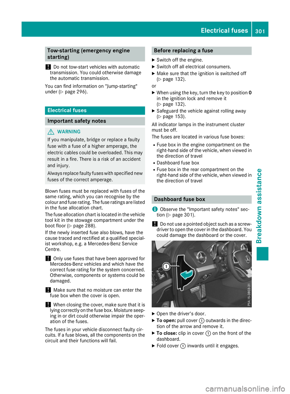
the direction of travel Dashboard fuse box
i Observe the "Important safety notes" sec-
tion (Y page 301).
! Do not use a pointed object such as a screw-
driver to open the cover in the dashboard. You could damage the dashboard or the cover. X
Open the driver's door.
X To open: pull cover :outwards in the direc-
tion of the arrow and remove it.
X To close: clip in cover :on the front of the
dashboard.
X Fold cover :inwards until it engages. Electrical fuses
301Breakdown assistance Z
Page 305 of 333

Fuse box in the engine compartment
i Observe the "Important safety notes" sec-
tion (Y page 301). G
WARNING
When the bonnet is open, and the windscreen wipers are set in motion, you can be injured by
the wiper linkage. There is a risk of injury.
Always switch off the windscreen wipers and
the ignition before opening the bonnet. X
Open the bonnet.
X Remove any existing moisture from the fuse
box using a dry cloth.
X To open: open clamps ;.
X Fold cover :of the fuse box up in the direc-
tion of the arrow and remove it. X
To close: check whether the seal is lying cor-
rectly in cover :.
X Insert both openings =at the rear of
cover :into the brackets on the fuse box.
The brackets on the fuse box must be com-
pletely visible in both openings =on the fuse
box.
X Fold down cover :.
X Hook clamps ;into the fuse box and close. X
Close the bonnet. Fuse box in the rear
i Observe the "Important safety notes" sec-
tion (Y page 301). The fuse box in the rear is located on the right-hand
side when viewed in the direction of travel.
X To open: open the seat belt guide on the
right-hand seat and remove the seat belt
(Y page 103).
X Move the right-hand seat as far forward as
possible (Y page 104).
X Insert your fingers at the bottom of front
cover ;between the cover and floor cover-
ing.
X Remove front cover ;by pulling it forward in
the direction of the arrow.
X Lift off top cover :by pulling it in the direc-
tion of the arrow. Fuses
=are accessible through the two open-
ings in the top of the fuse box. 302
Electrical fusesBreakdown assistance