Page 291 of 333

X
Lift and swing out bracket =from the side on
which locking button ?is located.
X Take fire extinguisher ;out of the roller box.
X To insert: insert fire extinguisher ;into the
roller box.
X Insert bracket =into the roller box on the
side opposite locking button ?.
X Then, insert bracket =completely.
X Slide locking button ?in the opposite direc-
tion to the arrow.
X Check whether bracket =is properly
engaged.
X Close cover :.
Have the fire extinguisher refilled after each use and checked every one or two years. It may oth-
erwise fail in an emergency. Vehicle tool kit
General notes The towing eye is located in the boot in a bracket
below the boot lid lock.
If the vehicle is equipped with a TIREFIT kit, it is located in the stowage well under the floor of the
boot.
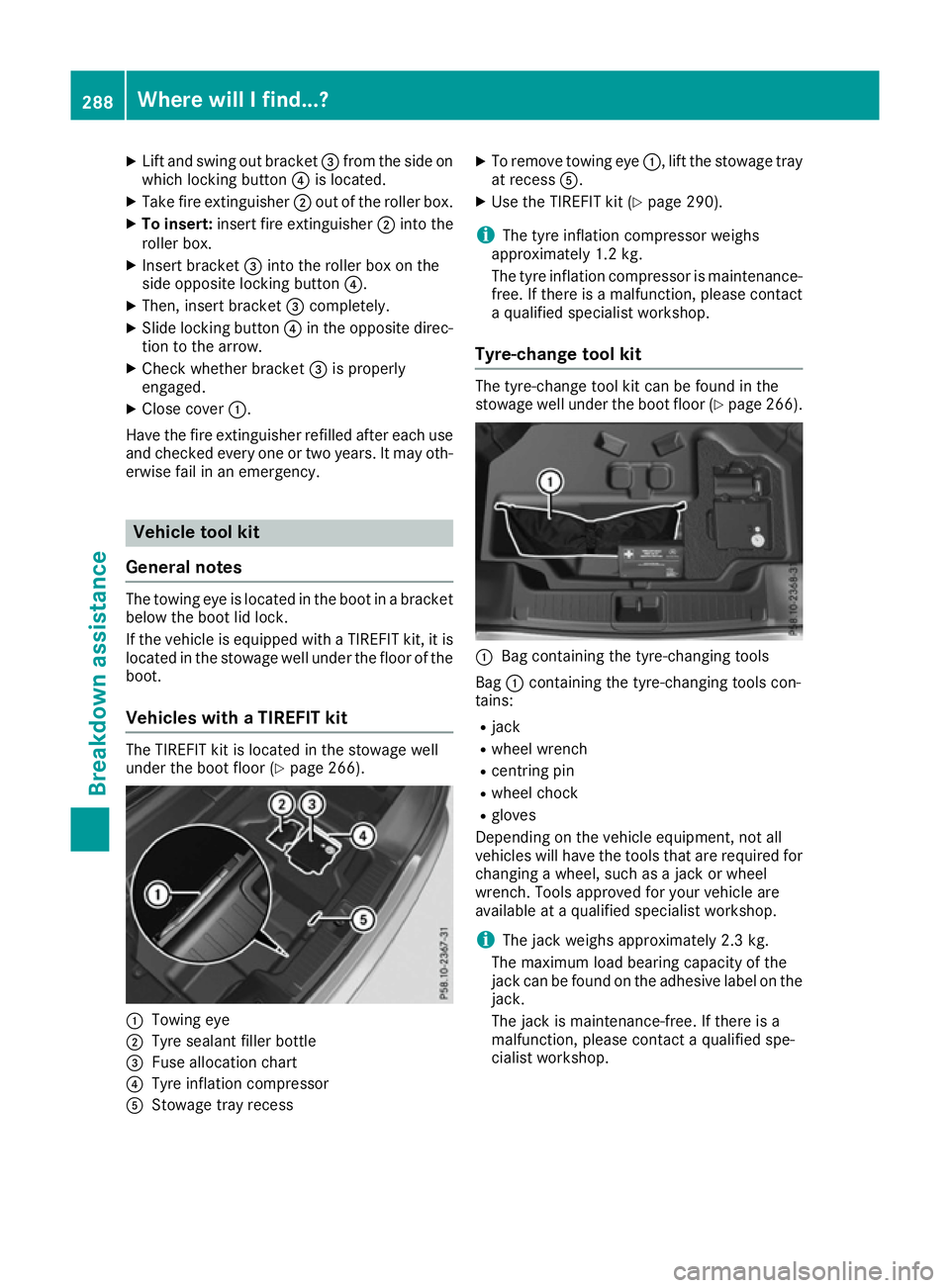
Vehicles with a TIREFIT kit The TIREFIT kit is located in the stowage well
under the boot floor (Y page 266).:
Towing eye
; Tyre sealant filler bottle
= Fuse allocation chart
? Tyre inflation compressor
A Stowage tray recess X
To remove towing eye :, lift the stowage tray
at recess A.
X Use the TIREFIT kit (Y page 290).
i The tyre inflation compressor weighs
approximately 1.2 kg.
The tyre inflation compressor is maintenance-
free. If there is a malfunction, please contact a qualified specialist workshop.
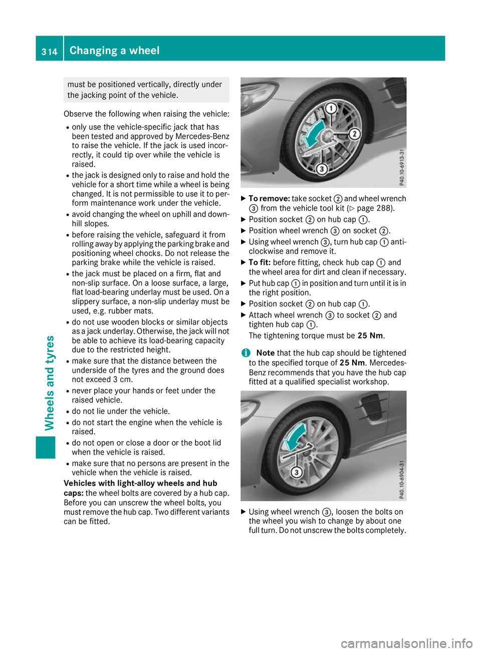
Tyre-change tool kit The tyre-change tool kit can be found in the
stowage well under the boot floor (Y
page 266). :
Bag containing the tyre-changing tools
Bag :containing the tyre-changing tools con-
tains:
R jack
R wheel wrench
R centring pin
R wheel chock
R gloves
Depending on the vehicle equipment, not all
vehicles will have the tools that are required for
changing a wheel, such as a jack or wheel
wrench. Tools approved for your vehicle are
available at a qualified specialist workshop.
i The jack weighs approximately 2.3 kg.
The maximum load bearing capacity of the
jack can be found on the adhesive label on the jack.
The jack is maintenance-free. If there is a
malfunction, please contact a qualified spe-
cialist workshop. 288
Where will I find...?Breakdown assistance
Page 317 of 333

must be positioned vertically, directly under
the jacking point of the vehicle.
Observe the following when raising the vehicle:
R only use the vehicle-specific jack that has
been tested and approved by Mercedes-Benz
to raise the vehicle. If the jack is used incor-
rectly, it could tip over while the vehicle is
raised.
R the jack is designed only to raise and hold the
vehicle for a short time while a wheel is being
changed. It is not permissible to use it to per- form maintenance work under the vehicle.
R avoid changing the wheel on uphill and down-
hill slopes.
R before raising the vehicle, safeguard it from
rolling away by applying the parking brake and
positioning wheel chocks. Do not release the parking brake while the vehicle is raised.
R the jack must be placed on a firm, flat and
non-slip surface. On a loose surface, a large,
flat load-bearing underlay must be used. On a
slippery surface, a non-slip underlay must be
used, e.g. rubber mats.
R do not use wooden blocks or similar objects
as a jack underlay. Otherwise, the jack will not
be able to achieve its load-bearing capacity
due to the restricted height.
R make sure that the distance between the
underside of the tyres and the ground does
not exceed 3 cm.
R never place your hands or feet under the
raised vehicle.
R do not lie under the vehicle.
R do not start the engine when the vehicle is
raised.
R do not open or close a door or the boot lid
when the vehicle is raised.
R make sure that no persons are present in the
vehicle when the vehicle is raised.
Vehicles with light-alloy wheels and hub
caps: the wheel bolts are covered by a hub cap.
Before you can unscrew the wheel bolts, you
must remove the hub cap. Two different variants
can be fitted. X
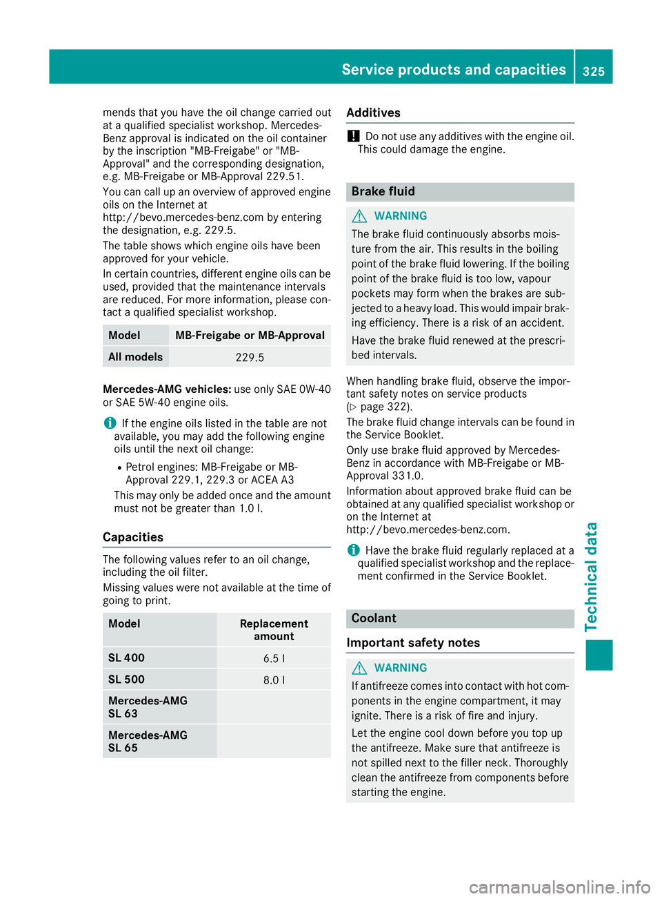
To remove: take socket;and wheel wrench
= from the vehicle tool kit (Y page 288).
X Position socket ;on hub cap :.
X Position wheel wrench =on socket ;.
X Using wheel wrench =, turn hub cap:anti-
clockwise and remove it.
X To fit: before fitting, check hub cap :and
the wheel area for dirt and clean if necessary.
X Put hub cap :in position and turn until it is in
the right position.
X Position socket ;on hub cap :.
X Attach wheel wrench =to socket ;and
tighten hub cap :.
The tightening torque must be 25 Nm.
i Note
that the hub cap should be tightened
to the specified torque of 25 Nm. Mercedes-
Benz recommends that you have the hub cap
fitted at a qualified specialist workshop. X
Using wheel wrench =, loosen the bolts on
the wheel you wish to change by about one
full turn. Do not unscrew the bolts completely. 314
Changing a wheelWheels and tyres
Page 328 of 333

mends that you have the oil change carried out
at a qualified specialist workshop. Mercedes-
Benz approval is indicated on the oil container
by the inscription "MB-Freigabe" or "MB-
Approval" and the corresponding designation,
e.g. MB-Freigabe or MB-Approval 229.51.
You can call up an overview of approved engine
oils on the Internet at
http://bevo.mercedes-benz.com by entering
the designation, e.g. 229.5.
The table shows which engine oils have been
approved for your vehicle.
In certain countries, different engine oils can be used, provided that the maintenance intervals
are reduced. For more information, please con-
tact a qualified specialist workshop. Model MB-Freigabe or MB-Approval
All models
229.5
Mercedes‑AMG vehicles:
use only SAE 0W-40
or SAE 5W-40 engine oils.
i If the engine oils listed in the table are not
available, you may add the following engine
oils until the next oil change:
R Petrol engines: MB-Freigabe or MB-
Approval 229.1, 229.3 or ACEA A3
This may only be added once and the amount must not be greater than 1.0 l.
Capacities The following values refer to an oil change,
including the oil filter.
Missing values were not available at the time of
going to print. Model Replacement
amount SL 400
6.5 l
SL 500
8.0 l
Mercedes‑AMG
SL 63 Mercedes‑AMG
SL 65 Additives
!
Do not use any additives with the engine oil.
This could damage the engine. Brake fluid
G
WARNING
The brake fluid continuously absorbs mois-
ture from the air. This results in the boiling
point of the brake fluid lowering. If the boiling
point of the brake fluid is too low, vapour
pockets may form when the brakes are sub-
jected to a heavy load. This would impair brak- ing efficiency. There is a risk of an accident.
Have the brake fluid renewed at the prescri-
bed intervals.
When handling brake fluid, observe the impor-
tant safety notes on service products
(Y page 322).
The brake fluid change intervals can be found in the Service Booklet.
Only use brake fluid approved by Mercedes-
Benz in accordance with MB-Freigabe or MB-
Approval 331.0.
Information about approved brake fluid can be
obtained at any qualified specialist workshop or on the Internet at
http://bevo.mercedes-benz.com.
i Have the brake fluid regularly replaced at a
qualified specialist workshop and the replace- ment confirmed in the Service Booklet. Coolant
Important safety notes G
WARNING
If antifreeze comes into contact with hot com- ponents in the engine compartment, it may
ignite. There is a risk of fire and injury.
Let the engine cool down before you top up
the antifreeze. Make sure that antifreeze is
not spilled next to the filler neck. Thoroughly
clean the antifreeze from components before
starting the engine. Service products and capacities
325Technical data Z
Page:
< prev 1-8 9-16 17-24