2016 MERCEDES-BENZ GLS SUV wheel
[x] Cancel search: wheelPage 375 of 397
X
Using wheel wrench :, loosen the bolts on
the wheel you wish to change by about one
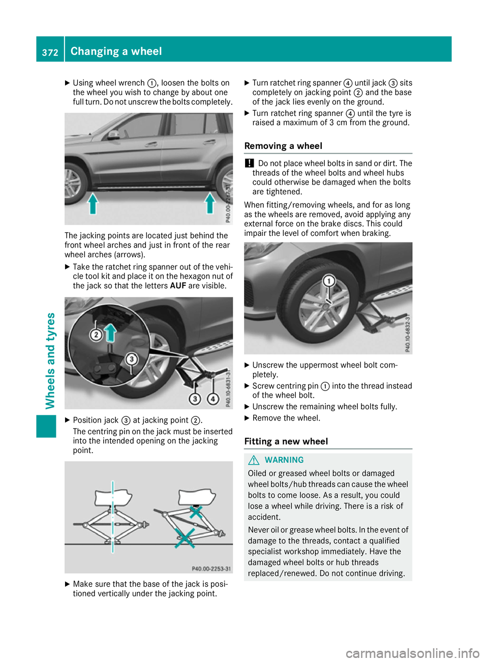
full turn. Do not unscrew the bolts completely. The jacking points are located just behind the
front wheel arches and just in front of the rear
wheel arches (arrows).
X Take the ratchet ring spanner out of the vehi-
cle tool kit and place it on the hexagon nut of
the jack so that the letters AUFare visible. X
Position jack =at jacking point ;.
The centring pin on the jack must be inserted into the intended opening on the jacking
point. X
Make sure that the base of the jack is posi-
tioned vertically under the jacking point. X
Turn ratchet ring spanner ?until jack =sits
completely on jacking point ;and the base
of the jack lies evenly on the ground.
X Turn ratchet ring spanner ?until the tyre is
raised a maximum of 3 cm from the ground.
Removing a wheel !
Do not place wheel bolts in sand or dirt. The
threads of the wheel bolts and wheel hubs
could otherwise be damaged when the bolts
are tightened.
When fitting/removing wheels, and for as long
as the wheels are removed, avoid applying any
external force on the brake discs. This could
impair the level of comfort when braking. X
Unscrew the uppermost wheel bolt com-
pletely.
X Screw centring pin :into the thread instead
of the wheel bolt.
X Unscrew the remaining wheel bolts fully.
X Remove the wheel.
Fitting a new wheel G
WARNING
Oiled or greased wheel bolts or damaged
wheel bolts/hub threads can cause the wheel bolts to come loose. As a result, you could
lose a wheel while driving. There is a risk of
accident.
Never oil or grease wheel bolts. In the event ofdamage to the threads, contact a qualified
specialist workshop immediately. Have the
damaged wheel bolts or hub threads
replaced/renewed. Do not continue driving. 372
Changing a wheelWheels and tyres
Page 376 of 397
G
WARNING
If you tighten the wheel bolts or wheel nuts
when the vehicle is raised, the jack could tip
over. There is a risk of injury.
Only tighten the wheel bolts or wheel nuts
when the vehicle is on the ground.
It is imperative to observe the instructions and
safety notes on "Changing a wheel"
(Y page 369).
Only use wheel bolts that have been designed
for the wheel and the vehicle. For safety rea-
sons, Mercedes-Benz recommends that you
only use wheel bolts which have been approved for Mercedes-Benz vehicles and the respective
wheel.
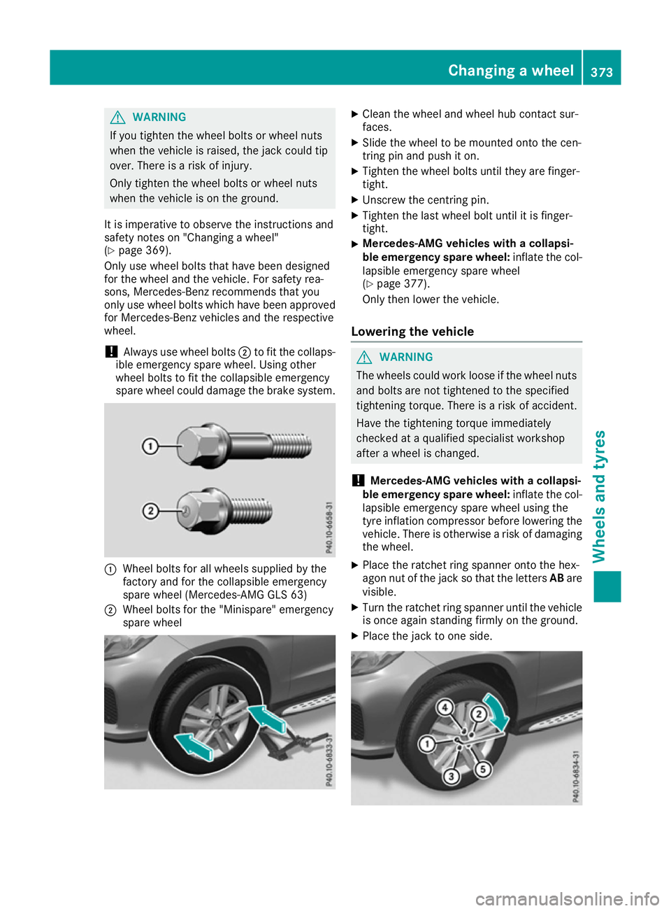
! Always use wheel bolts
;to fit the collaps-
ible emergency spare wheel. Using other
wheel bolts to fit the collapsible emergency
spare wheel could damage the brake system. :
Wheel bolts for all wheels supplied by the
factory and for the collapsible emergency
spare wheel (Mercedes-AMG GLS 63)
; Wheel bolts for the "Minispare" emergency
spare wheel X
Clean the wheel and wheel hub contact sur-
faces.
X Slide the wheel to be mounted onto the cen-
tring pin and push it on.
X Tighten the wheel bolts until they are finger-
tight.
X Unscrew the centring pin.
X Tighten the last wheel bolt until it is finger-
tight.
X Mercedes-AMG vehicles with a collapsi-
ble emergency spare wheel:
inflate the col-
lapsible emergency spare wheel
(Y page 377).
Only then lower the vehicle.
Lowering the vehicle G
WARNING
The wheels could work loose if the wheel nuts and bolts are not tightened to the specified
tightening torque. There is a risk of accident.
Have the tightening torque immediately
checked at a qualified specialist workshop
after a wheel is changed.
! Mercedes-AMG vehicles with a collapsi-
ble emergency spare wheel: inflate the col-
lapsible emergency spare wheel using the
tyre inflation compressor before lowering the vehicle. There is otherwise a risk of damaging
the wheel.
X Place the ratchet ring spanner onto the hex-
agon nut of the jack so that the letters ABare
visible.
X Turn the ratchet ring spanner until the vehicle
is once again standing firmly on the ground.
X Place the jack to one side. Changing a wheel
373Wheels and tyres Z
Page 377 of 397
X
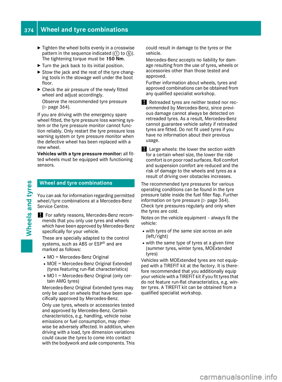
Tighten the wheel bolts evenly in a crosswise
pattern in the sequence indicated (: toA).
The tightening torque must be 150 Nm.
X Turn the jack back to its initial position.
X Stow the jack and the rest of the tyre chang-
ing tools in the stowage well under the boot
floor.
X Check the air pressure of the newly fitted
wheel and adjust accordingly.
Observe the recommended tyre pressure
(Y page 364).
If you are driving with the emergency spare
wheel fitted, the tyre pressure loss warning sys-
tem or the tyre pressure monitor cannot func-
tion reliably. Only restart the tyre pressure loss
warning system or tyre pressure monitor when
the defective wheel has been replaced with a
new wheel.
Vehicles with a tyre pressure monitor: all fit-
ted wheels must be equipped with functioning
sensors. Wheel and tyre combinations
You can ask for information regarding permitted wheel/tyre combinations at a Mercedes-Benz
Service Centre.
! For safety reasons, Mercedes-Benz recom-
mends that you only use tyres and wheels
which have been approved by Mercedes-Benz specifically for your vehicle.
These are specially adapted to the control
systems, such as ABS or ESP ®
and are
marked as follows:
R MO = Mercedes-Benz Original
R MOE = Mercedes-Benz Original Extended
(tyres featuring run-flat characteristics)
R MO1 = Mercedes-Benz Original (only cer-
tain AMG tyres)
Mercedes-Benz Original Extended tyres may
only be used on wheels that have been spe-
cifically approved by Mercedes-Benz.
Only use tyres, wheels or accessories tested
and approved by Mercedes-Benz. Certain
characteristics, e.g. handling, vehicle noise
emissions or fuel consumption, may other-
wise be adversely affected. In addition, when
driving with a load, tyre dimension variations
could cause the tyres to come into contact
with the bodywork and axle components. This could result in damage to the tyres or the
vehicle.
Mercedes-Benz accepts no liability for dam-
age resulting from the use of tyres, wheels or
accessories other than those tested and
approved.
Further information about wheels, tyres and
approved combinations can be obtained from any qualified specialist workshop.
! Retreaded tyres are neither tested nor rec-
ommended by Mercedes-Benz, since previ-
ous damage cannot always be detected on
retreaded tyres. As a result, Mercedes-Benz
cannot guarantee vehicle safety if retreaded
tyres are fitted. Do not fit used tyres if you
have no information about their previous
usage.
! Large wheels: the lower the section width
for a certain wheel size, the lower the ride
comfort is on poor road surfaces. Roll comfort and suspension comfort are reduced and therisk of damage to the wheels and tyres as a
result of driving over obstacles increases.
The recommended tyre pressures for various
operating conditions can be found in the tyre
pressure table inside the fuel filler flap. Further
information on tyre pressure (Y page 364).
Check tyre pressures regularly and only when
the tyres are cold.
Notes on the vehicle equipment – always fit the
vehicle:
R with tyres of the same size across an axle
(left/right)
R with the same type of tyres at a given time
(summer tyres, winter tyres, MOExtended
tyres)
Vehicles with MOExtended tyres are not equip-
ped with a TIREFIT kit at the factory. It is there-
fore recommended that you additionally equip
your vehicle with a TIREFIT kit if you fit tyres that do not feature run-flat characteristics, e.g. win-
ter tyres. A TIREFIT kit can be obtained from a
qualified specialist workshop. 374
Wheel and tyre combinationsWheels and tyres
Page 378 of 397
Emergency spare wheel
Important safety notes
G
WARNING
The wheel/tyre dimensions and the tyre type of the spare wheel/emergency spare wheel
and the wheel to be replaced may differ. Fit-
ting a spare wheel/emergency spare wheel
may severely impair the driving characteris-
tics. There is a risk of accident.
To prevent hazardous situations:
R Adapt your driving style accordingly and
drive carefully.
R Never fit more than one spare wheel/emer-
gency spare wheel if the dimensions are
different to those of the wheel being
replaced.
R Only use a spare wheel/emergency spare
wheel briefly if the dimensions are different
to those of the wheel being replaced.
R Do not switch off ESP ®
.
R Have the spare wheel/emergency spare
wheel in question replaced at the nearest
qualified specialist workshop. Make sure
that the wheel/tyre dimensions and tyre
type are correct.
! Mercedes-AMG vehicles with
"Minispare" emergency spare wheel: only
use the "Minispare" emergency spare wheel
on the rear axle. If you fit the "Minispare"
emergency spare wheel to the front axle, the braking system could be damaged.
If a tyre on the front axle is damaged, an
undamaged wheel on the rear axle must be
replaced first with the "Minispare" emergency
spare wheel. The damaged wheel on the front
axle can then be replaced by the undamaged wheel from the rear axle.
You must observe the instruction label on the"Minispare" emergency spare wheel.
When using an emergency spare wheel or spare wheel of a different size, you must not exceed
the maximum speed of 80 km/h.
Snow chains must not be fitted to emergency
spare wheels. General notes
You can ask for information regarding permitted emergency spare wheels at a Mercedes-Benz
Service Centre.
Fitting the emergency spare wheel is described under "Fitting a wheel" (Y page 370).
You should check the pressure of all your tyres, including the emergency spare wheel, regularly
as well as prior to long trips, and correct the
pressure as necessary (Y page 364). The value
on the wheel is valid.
An emergency spare wheel may also be fitted
against the direction of rotation. Observe the
time restriction on use as well as the speed lim- itation specified on the emergency spare wheel.
Replace the tyres after six years at the latest,
regardless of wear. This also applies to the
emergency spare wheel.
If you are driving with the emergency spare
wheel fitted, the tyre pressure loss warning sys- tem or the tyre pressure monitor cannot func-
tion reliably. Restart the tyre pressure loss warn-
ing system or tyre pressure monitor only once
the defective wheel has been replaced with a
new wheel.
Vehicles with tyre pressure monitor: after an
emergency spare wheel has been fitted, the sys- tem may still display the tyre pressure of the
removed wheel for a few minutes. The value dis-
played for the position where the emergency
spare wheel is fitted is not the same as the cur- rent tyre pressure of the emergency spare
wheel. Removing/stowing the emergency
spare wheel
Vehicles with a "Minispare" emergency
spare wheel under the luggage com-
partment floor Observe the instructions and safety notes in the
"Fitting a wheel" section (Y page 370).
Example image: vehicle without lockable lug-
gage compartment floor. Emergency spare wheel
375Wheels and tyres Z
Page 379 of 397
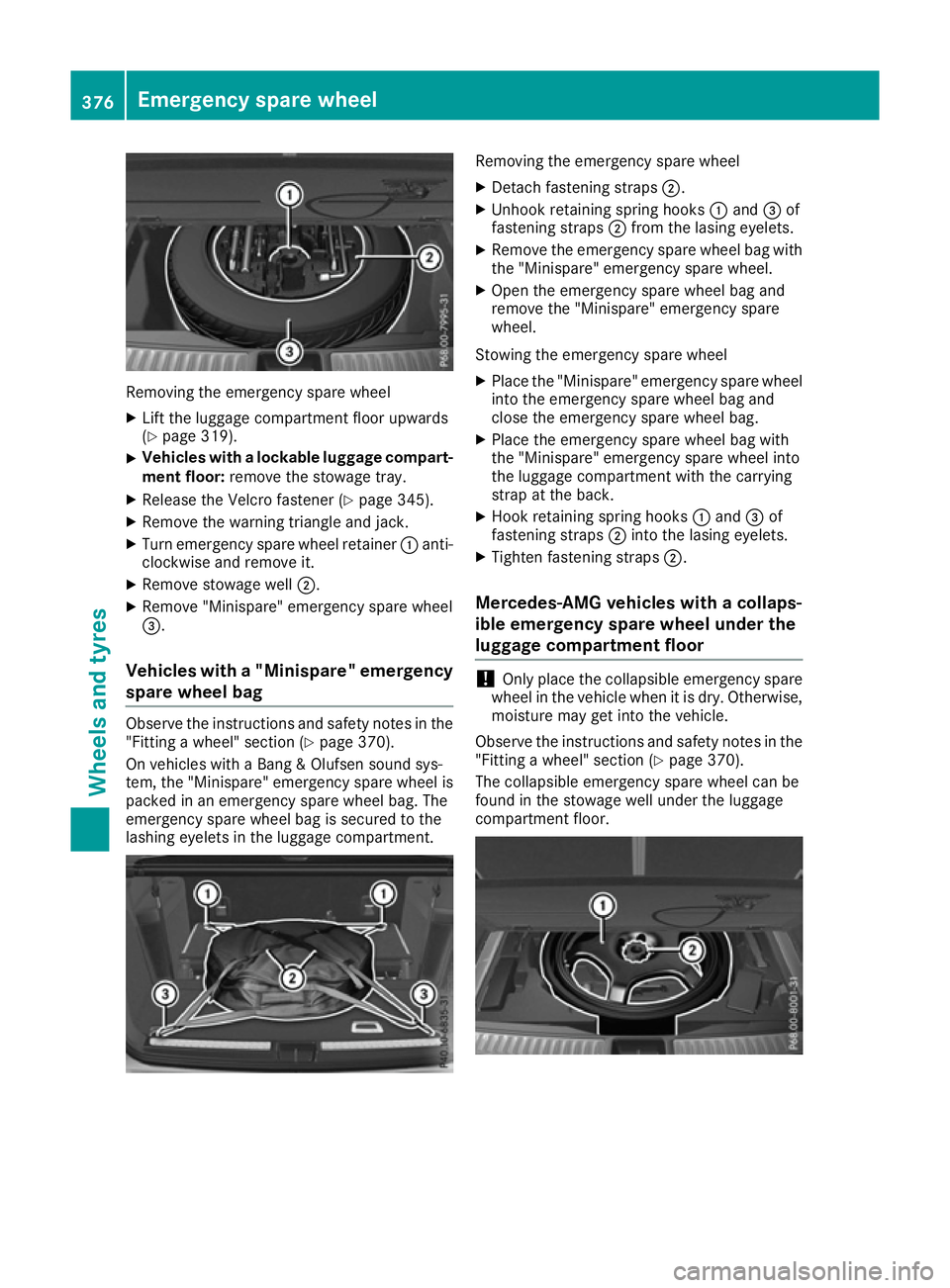
Removing the emergency spare wheel
X Lift the luggage compartment floor upwards
(Y page 319).
X Vehicles with a lockable luggage compart-
ment floor: remove the stowage tray.
X Release the Velcro fastener (Y page 345).
X Remove the warning triangle and jack.
X Turn emergency spare wheel retainer :anti-
clockwise and remove it.
X Remove stowage well ;.
X Remove "Minispare" emergency spare wheel
=.
Vehicles with a "Minispare" emergency spare wheel bag Observe the instructions and safety notes in the
"Fitting a wheel" section (Y page 370).
On vehicles with a Bang & Olufsen sound sys-
tem, the "Minispare" emergency spare wheel is
packed in an emergency spare wheel bag. The
emergency spare wheel bag is secured to the
lashing eyelets in the luggage compartment. Removing the emergency spare wheel
X Detach fastening straps ;.
X Unhook retaining spring hooks :and =of
fastening straps ;from the lasing eyelets.
X Remove the emergency spare wheel bag with
the "Minispare" emergency spare wheel.
X Open the emergency spare wheel bag and
remove the "Minispare" emergency spare
wheel.
Stowing the emergency spare wheel
X Place the "Minispare" emergency spare wheel
into the emergency spare wheel bag and
close the emergency spare wheel bag.
X Place the emergency spare wheel bag with
the "Minispare" emergency spare wheel into
the luggage compartment with the carrying
strap at the back.
X Hook retaining spring hooks :and =of
fastening straps ;into the lasing eyelets.
X Tighten fastening straps ;.
Mercedes-AMG vehicles with a collaps-
ible emergency spare wheel under the
luggage compartment floor !
Only place the collapsible emergency spare
wheel in the vehicle when it is dry. Otherwise,
moisture may get into the vehicle.
Observe the instructions and safety notes in the
"Fitting a wheel" section (Y page 370).
The collapsible emergency spare wheel can be
found in the stowage well under the luggage
compartment floor. 376
Emergency spare wheelWheels and ty
res
Page 380 of 397
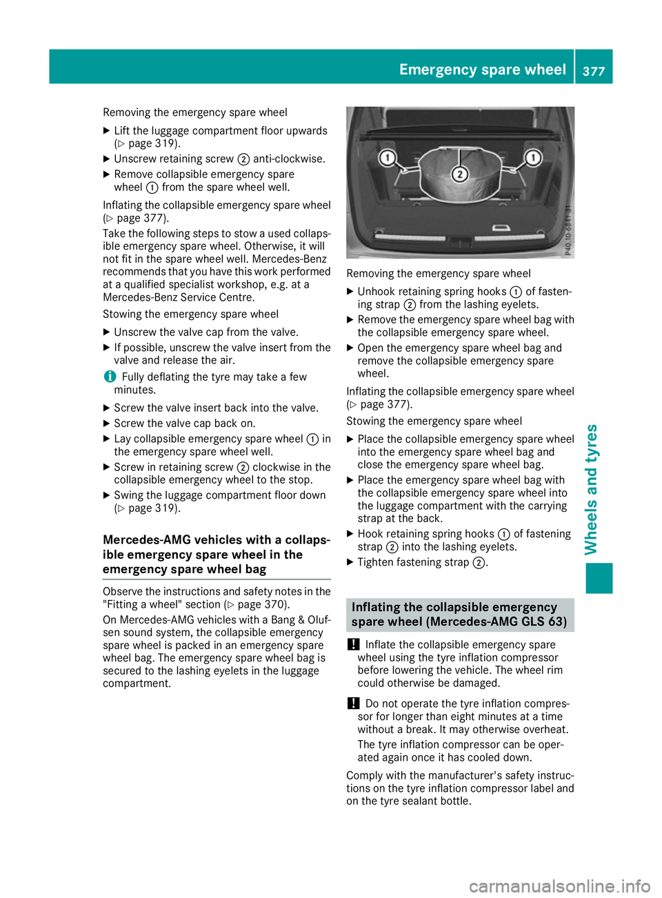
Removing the emergency spare wheel
X Lift the luggage compartment floor upwards
(Y page 319).
X Unscrew retaining screw ;anti-clockwise.
X Remove collapsible emergency spare
wheel :from the spare wheel well.
Inflating the collapsible emergency spare wheel (Y page 377).
Take the following steps to stow a used collaps-
ible emergency spare wheel. Otherwise, it will
not fit in the spare wheel well. Mercedes-Benz
recommends that you have this work performed
at a qualified specialist workshop, e.g. at a
Mercedes-Benz Service Centre.
Stowing the emergency spare wheel
X Unscrew the valve cap from the valve.
X If possible, unscrew the valve insert from the
valve and release the air.
i Fully deflating the tyre may take a few
minutes.
X Screw the valve insert back into the valve.
X Screw the valve cap back on.
X Lay collapsible emergency spare wheel :in
the emergency spare wheel well.
X Screw in retaining screw ;clockwise in the
collapsible emergency wheel to the stop.
X Swing the luggage compartment floor down
(Y page 319).
Mercedes-AMG vehicles with a collaps-
ible emergency spare wheel in the
emergency spare wheel bag Observe the instructions and safety notes in the
"Fitting a wheel" section (Y page 370).
On Mercedes-AMG vehicles with a Bang & Oluf-
sen sound system, the collapsible emergency
spare wheel is packed in an emergency spare
wheel bag. The emergency spare wheel bag is
secured to the lashing eyelets in the luggage
compartment. Removing the emergency spare wheel
X Unhook retaining spring hooks :of fasten-
ing strap ;from the lashing eyelets.
X Remove the emergency spare wheel bag with
the collapsible emergency spare wheel.
X Open the emergency spare wheel bag and
remove the collapsible emergency spare
wheel.
Inflating the collapsible emergency spare wheel (Y page 377).
Stowing the emergency spare wheel
X Place the collapsible emergency spare wheel
into the emergency spare wheel bag and
close the emergency spare wheel bag.
X Place the emergency spare wheel bag with
the collapsible emergency spare wheel into
the luggage compartment with the carrying
strap at the back.
X Hook retaining spring hooks :of fastening
strap ;into the lashing eyelets.
X Tighten fastening strap ;. Inflating the collapsible emergency
spare wheel (Mercedes-AMG GLS 63)
! Inflate the collapsible emergency spare
wheel using the tyre inflation compressor
before lowering the vehicle. The wheel rim
could otherwise be damaged.
! Do not operate the tyre inflation compres-
sor for longer than eight minutes at a time
without a break. It may otherwise overheat.
The tyre inflation compressor can be oper-
ated again once it has cooled down.
Comply with the manufacturer's safety instruc-
tions on the tyre inflation compressor label and
on the tyre sealant bottle. Emergency spare wheel
377Wheels and tyres Z
Page 381 of 397
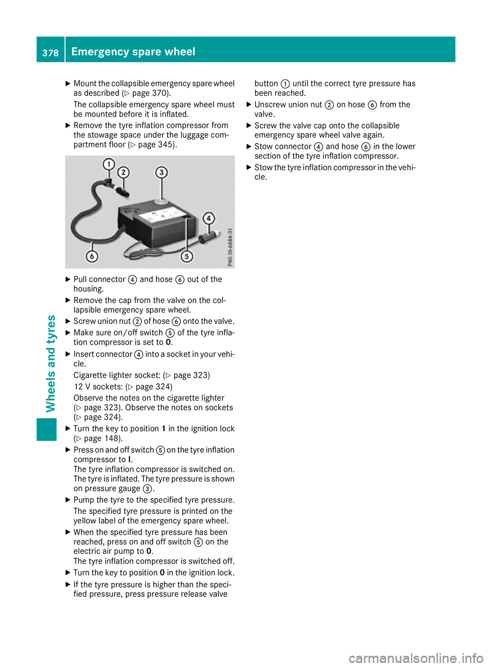
X
Mount the collapsible emergency spare wheel
as described (Y page 370).
The collapsible emergency spare wheel must
be mounted before it is inflated.
X Remove the tyre inflation compressor from
the stowage space under the luggage com-
partment floor (Y page 345). X
Pull connector ?and hose Bout of the
housing.
X Remove the cap from the valve on the col-
lapsible emergency spare wheel.
X Screw union nut ;of hose Bonto the valve.
X Make sure on/off switch Aof the tyre infla-
tion compressor is set to 0.
X Insert connector ?into a socket in your vehi-
cle.
Cigarette lighter socket: (Y page 323)
12 V sockets: (Y page 324)
Observe the notes on the cigarette lighter
(Y page 323). Observe the notes on sockets
(Y page 324).
X Turn the key to position 1in the ignition lock
(Y page 148).
X Press on and off switch Aon the tyre inflation
compressor to I.
The tyre inflation compressor is switched on.
The tyre is inflated. The tyre pressure is shown
on pressure gauge =.
X Pump the tyre to the specified tyre pressure.
The specified tyre pressure is printed on the
yellow label of the emergency spare wheel.
X When the specified tyre pressure has been
reached, press on and off switch Aon the
electric air pump to 0.
The tyre inflation compressor is switched off.
X Turn the key to position 0in the ignition lock.
X If the tyre pressure is higher than the speci-
fied pressure, press pressure release valve button
:until the correct tyre pressure has
been reached.
X Unscrew union nut ;on hose Bfrom the
valve.
X Screw the valve cap onto the collapsible
emergency spare wheel valve again.
X Stow connector ?and hose Bin the lower
section of the tyre inflation compressor.
X Stow the tyre inflation compressor in the vehi-
cle. 378
Emergency spare wheelWheels and tyres
Page 391 of 397
All other mod-
els with: :
:
Height when
opened ;
;
Maximum
headroom AIRMATIC
package
2132 mm -
2207 mm 1934 mm -
2009 mm ON&OFFROAD
package
2132 mm -
2237 mm 1934 mm -
2039 mm Missing values were not available at the time of
going to print. Mercedes-AMG vehicles
Vehicle length
5162 mm
Vehicle width including
exterior mirrors
Vehicle width excluding
exterior mirrors
1982 mm
Vehicle height
1850 mm
Wheelbase
3075 mm
Maximum ground clear-
ance
Minimum ground clear-
ance
Maximum roof load
All other models
Vehicle length
5130 mm
Vehicle width including
exterior mirrors
2141 mm
Vehicle width excluding
exterior mirrors
1934 mm
Maximum vehicle height
(AIRMATIC package)
1910 mm
Maximum vehicle height
(ON&OFFROAD package)
1940 mm
Minimum vehicle height
1850 mm
Wheelbase
3075 mm
Maximum ground clear-
ance (AIRMATIC package)
276 mm All other models
Maximum ground clear-
ance (ON&OFFROAD pack-
age)
306 mm
Minimum ground clear-
ance
201 mm
Roof load
100 kg
Vehicle data for off-road driving
Fording depth
! The depth of water must not exceed the
value specified in the table. Note that the
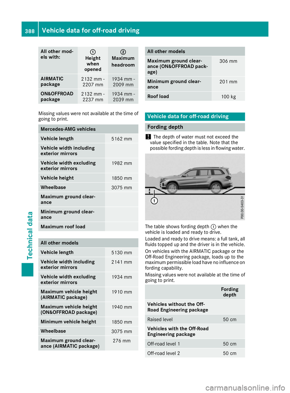
possible fording depth is less in flowing water. The table shows fording depth
:when the
vehicle is loaded and ready to drive.
Loaded and ready to drive means: a full tank, all fluids topped up and the driver is in the vehicle.
On vehicles with the AIRMATIC package or the
Off-Road Engineering package, loads up to the
maximum permissible load have no influence on fording capability.
Missing values were not available at the time of
going to print. Fording
depth Vehicles without the Off-
Road Engineering package
Raised level 50 cm
Vehicles with the Off-Road
Engineering package
Off-road level 1 50 cm
Off-road level 2 50 cm388
Vehicle data for off-road drivingTechnical data