2016 MERCEDES-BENZ GLE-CLASS COUPE lock
[x] Cancel search: lockPage 341 of 382

halt by braking carefully. Avoid abrupt steering
movements.
The tire pressure monitor has a yellow warning
lamp in the instrument cluster for indicating
pressure loss or a malfunction. Whether the
warning lamp flashes or lights up indicates
whether a tire pressure is too low or the tire
pressure monitor is malfunctioning:
Rif the warning lamp is lit continuously, the tire
pressure on one or more tires is significantly
too low. The tire pressure monitor is not mal-functioning.
Rif the warning lamp flashes for around a
minute and then remains lit constantly, the
tire pressure monitor is malfunctioning.
In addition to the warning lamp, a message
appears in the multifunction display. Observe
the information on display messages
(
Ypage 259).
It may take up to ten minutes for a malfunction of the tire pressure monitor to be indicated. A
malfunction will be indicated by the tire pres-
sure warning lamp flashing for approximately
one minute and then remaining lit. When the
malfunction has been rectified, the tire pressure
warning lamp goes out after a few minutes of
driving.
The tire pressure values indicated by the on-
board computer may differ from those meas-
ured at a gas station with a pressure gauge. The
tire pressures shown by the on-board computer
refer to those measured at sea level. At high
altitudes, the tire pressure values indicated by a
pressure gauge are higher than those shown by the on-board computer. In this case, do not
reduce the tire pressures.
The operation of the tire pressure monitor can
be affected by interference from radio transmit-
ting equipment (e.g. radio headphones, two-way
radios) that may be being operated in or near the vehicle.
Checking the tire pressure electroni-
cally
XMake sure that the SmartKey is in position 2
in the ignition lock (Ypage 134).
XPress the =or; button on the steering
wheel to select the Serv.menu.
XPress the9or: button to select
Tire Pressure.
XPress the abutton.
The current tire pressure of each tire is shown
in the multifunction display.
If the vehicle has been parked for longer than
20 minutes, the Tire pressure will be
displayed after driving a few minutesmessage appears.
After a teach-in process, the tire pressure mon-
itor automatically detects new wheels or new
sensors. As long as a clear allocation of the tire
pressure value to the individual wheels is not
possible, theTire
PressureMonitorActivedisplay message is shown instead of the tire
pressure display. The tire pressures are already
being monitored.
iIf an emergency spare wheel is mounted,
the system may continue to show the tire
pressure of the wheel that has been removed
for a few minutes. If this occurs, note that the
value displayed for the position where the
spare wheel is mounted is not the same as the
current tire pressure of the emergency spare
wheel.
Tire pressure monitor warning mes-
sages
If the tire pressure monitor detects a pressure
loss in one or more tires, a warning message is
shown in the multifunction display. The yellow
tire pressure warning lamp then lights up.
RIf the Please Correct Tire Pressuremessage appears in the multifunction display,
the tire pressure in at least one tire is too low.
The tire pressure must be corrected when the
opportunity arises.
RIf the Check Tiresmessage appears in the
multifunction display, the tire pressure in at
least one tire has dropped significantly. The
tires must be checked.
RIf the WarningTireMalfunctionmessage
appears in the multifunction display, the tire
pressure in at least one tire has dropped sud-
denly. The tires must be checked.
If the wheel positions on the vehicle are rotated, the tire pressures may be displayed for the
wrong positions for a short time. This is rectified
after a few minutes of driving, and the tire pres-
sures are displayed for the correct positions.
Tire pressure339
Wheels and tires
Z
Page 342 of 382

Restarting the tire pressure monitor
When you restart the tire pressure monitor, all
existing warning messages are deleted and the
warning lamps go out. The monitor uses the cur-
rently set tire pressures as the reference values
for monitoring. In most cases, the tire pressure
monitor will automatically detect the new refer-
ence values after you have changed the tire
pressure. However, you can also define refer-
ence values manually as described here. The tire
pressure monitor then monitors the new tire
pressure values.
XSet the tire pressure to the value recommen-
ded for the corresponding driving situation on
the Tire and Loading Information placard on
the driver's side B-pillar (
Ypage 333).
You can find more tire pressure values for
various operating conditions in the tire pres-
sure table inside the fuel filler flap
(
Ypage 333).
XMake sure that the tire pressure is correct on
all four wheels.
XMake sure that the SmartKey is in position 2
in the ignition lock.
XPress the =or; button on the steering
wheel to select the Serv.menu.
XPress the9or: button to select
Tire Pressure.
XPress the abutton.
The multifunction display shows the current
tire pressure for the individual tires or the
Tire pressure will be displayed
after driving a few minutesmessage.
XPress the :button.
The UseCurrentPressuresAsNewRef‐erenceValuesmessage appears in the mul-
tifunction display.
If you wish to confirm the restart:
XPress the abutton.
The TirePress.MonitorRestartedmes-
sage appears in the multifunction display.
After driving for a few minutes, the system
checks whether the current tire pressures are
within the specified range. The new tire pres-
sures are then accepted as reference values
and monitored.
If you wish to cancel the restart:
XPress the %button.
The tire pressure values stored at the last
restart will continue to be monitored.
Radio type approval for the tire pres-
sure monitor
CountryRadio type approval number
USAFCC ID: MRXMW2433A
FCC ID: MRXGG4
FCC ID: MRXMC34MA4
CanadaIC: 2546A-MW2433A
IC: 2546A-GG4
IC: 2546A-MC34MA4
Loading the vehicle
Instruction labels for tires and loads
GWARNING
Overloaded tires can overheat, causing a
blowout. Overloaded tires can also impair the steering and driving characteristics and lead
to brake failure. There is a risk of accident.
Observe the load rating of the tires. The load
rating must be at least half of the GAWR of
your vehicle. Never overload the tires by
exceeding the maximum load.
Two instruction labels on your vehicle show the maximum possible load.
(1) The Tire and Loading Information placard is on the B-pillar on the driver's side. The Tire
and Loading Information placard shows the
maximum permissible number of occu-
pants and the maximum permissible vehicle
load. It also contains details of the tire sizes
and corresponding pressures for tires
mounted at the factory.
(2) The vehicle identification plate is on the B- pillar on the driver's side. The vehicle iden-
tification plate informs you of the gross
vehicle weight rating. It is made up of the
vehicle weight, all vehicle occupants, the
fuel and the cargo. You can also find infor-
mation about the maximum gross axle
weight rating on the front and rear axle.
The maximum gross axle weight rating is
the maximum weight that can be carried by
one axle (front or rear axle). Never exceed
the maximum load or the maxi mum g
ross
axle weight rating for the front or rear axle.
340Loading the vehicle
Wheels and tires
Page 354 of 382

be required earlier. Do not change the direction
of wheel rotation.
Clean the contact surfaces of the wheel and the
brake disc thoroughly every time a wheel is rota-ted. Check the tire pressure and, if necessary,
restart the tire pressure loss warning system or
the tire pressure monitor.
Direction of rotation
Tires with a specified direction of rotation have
additional benefits, e.g. if there is a risk of hydro-
planing. These advantages can only be gained if
the tires are installed corresponding to the
direction of rotation.
An arrow on the sidewall of the tire indicates its
correct direction of rotation.
Storing wheels
Store wheels that are not being used in a cool,
dry and preferably dark place. Protect the tires
from oil, grease, gasoline and diesel.
Mounting a wheel
Preparing the vehicle
XVehicle with emergency spare wheel:
when mounting the emergency spare wheel in
the event of a flat tire, follow the additional
notes on vehicle preparation under "Flat tire"
(
Ypage 315).
XStop the vehicle on solid, non-slippery and
level ground.
XApply the electric parking brake manually.
XUnload heavy luggage.
XBring the front wheels into the straight-ahead position.
XShift the transmission to position P.
XVehicles with the AIRMATIC package:
make sure that the normal vehicle level is
selected (
Ypage 183).
XSwitch off the engine.
XVehicles without KEYLESS-GO:remove the
SmartKey from the ignition lock.
XVehicles with KEYLESS-GO: open the driv-
er's door.
The on-board electronics now have status 0.
This is the same as the SmartKey having been
removed.
XVehicles with KEYLESS-GO: remove the
Start/Stop button from the ignition lock
(
Ypage 134).
XMake sure that the engine cannot be started
via your smartphone (Ypage 136).
XIf included in the vehicle equipment, remove
the tire-change tool kit from the vehicle.
XSafeguard the vehicle against rolling away.
iApart from certain country-specific varia-
tions, vehicles are not equipped with a tire-
change tool kit. For information on which
tools are required to perform a wheel change
on your vehicle, consult an authorized
Mercedes-Benz Center.
Necessary tire-changing tools can include, for example:
RJack
RWheel chock
RLug wrench
Securing the vehicle to prevent it from
rolling away
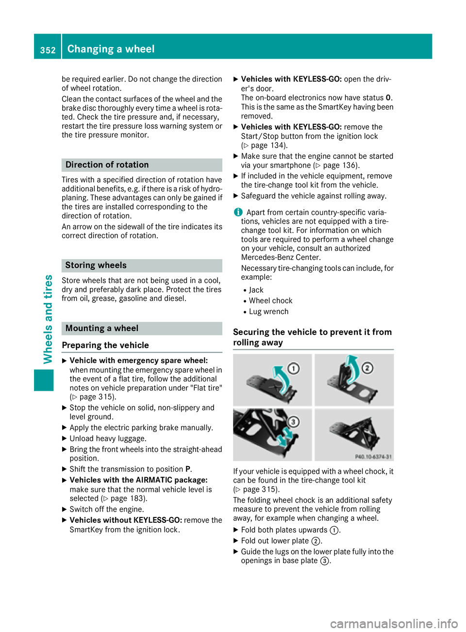
If your vehicle is equipped with a wheel chock, itcan be found in the tire-change tool kit
(
Ypage 315).
The folding wheel chock is an additional safety
measure to prevent the vehicle from rolling
away, for example when changing a wheel.
XFold both plates upwards :.
XFold out lower plate;.
XGuide the lugs on the lower plate fully into the
openings in base plate =.
352Changing a wheel
Wheels and tires
Page 355 of 382

XPlace chocks or other suitable items under
the front and rear of the wheel that is diago-
nally opposite the wheel you wish to change.
Raising the vehicle
GWARNING
If you do not position the jack correctly at the
appropriate jacking point of the vehicle, the
jack could tip over with the vehicle raised.
There is a risk of injury.
Only position the jack at the appropriate jack-
ing point of the vehicle. The base of the jack
must be positioned vertically, directly under
the jacking point of the vehicle.
!The jack is designed exclusively for jacking
up the vehicle at the jacking points. Other-
wise, your vehicle could be damaged.
Observe the following when raising the vehi-
cle:
RTo raise the vehicle, only use the vehicle-spe-
cific jack that has been tested and approved
by Mercedes-Benz. If used incorrectly, the
jack could tip over with the vehicle raised.
RThe jack is designed only to raise and hold the
vehicle for a short time while a wheel is being
changed. It must not be used for performing
maintenance work under the vehicle.
RAvoid changing the wheel on uphill and down-
hill slopes.
RBefore raising the vehicle, secure it from roll-
ing away by applying the parking brake and
inserting wheel chocks. Do not disengage the
parking brake while the vehicle is raised.
RThe jack must be placed on a firm, flat and
non-slip surface. On a loose surface, a large,
flat, load-bearing underlay must be used. On a slippery surface, a non-slip underlay must be
used, e.g. rubber mats.
RDo not use wooden blocks or similar objects
as a jack underlay. Otherwise, the jack will not
be able to achieve its load-bearing capacity
due to the restricted height.
RMake sure that the distance between the
underside of the tires and the ground does not
exceed 1.2 in (3 cm).
RDo not place your hands or feet under the
raised vehicle.
RDo not lie under the vehicle.
RDo not start the engine when the vehicle is
raised.
RNever open or close a door or the tailgate
when the vehicle is raised.
RMake sure that no persons are present in the
vehicle when the vehicle is raised.
XUsing lug wrench :, loosen the bolts on the
wheel you wish to change by about one full
turn. Do not unscrew the bolts completely.
The jacking points are located just behind the
front wheel housings and just in front of the rear
wheel housings (arrows).
XTake the ratchet wrench out of the vehicle
tool kit and place it on the hexagon nut of the
jack so that the letters AUFare visible.
Changing a wheel353
Wheels and tires
Z
Page 363 of 382

Replaceth etires after six years at th elatest ,
regardless of wear .This also applie sto th e
emergenc yspar ewheel.
iWhen you are driving wit hth ecollapsible
spar ewhee lmounted, th etire pressur eloss
warning system or th etire pressur emonitor
canno tfunction reliably. Only restar tth etire
pressur eloss warning system or tire pressur e
monitor when th edefective whee lhas been
replace dwit h a newwheel.
Vehicles with tire pressure monitor: after
mounting an emergenc yspar ewheel, th esys-
te m may still display th etire pressur eof th e
remove dwhee lfor afew minutes. The value
displayed for th emounte demergenc yspar e
whee lis no tth esam eas th ecurren ttire pres-
sur eof th eemergenc yspar ewheel.
Removing/stowing the emergency
spare wheel
Vehicles with a "Minispare" emergency
spare wheel under the cargo compart-
ment floor
Always observ eth einstruction sand safet y
note sin th e"Mounting awheel" section
(
Ypage 352).
The "Minispare" emergenc yspar ewhee lcan be
foun din th estowage well under th ecargo com-
partmen tfloor.
Removin gth eemergenc yspar ewhee l
XLiftth ecargo compartmen tfloor upwards
(Ypage 284).
XTurn retaining screw ;counter-clockwise
and remove it .
XRemove "Minispare" emergenc yspar e
whee l:.
Vehicles with a "Minispare" emergency
spare wheel in the emergency spare
wheel bag
Always observ eth einstruction sand safet y
note sin th e"Mounting awheel" section
(
Ypage 352).
On vehicles wit h aBan g & Olufsen soun dsys-
tem, th e"Minispare" emergenc yspar ewhee lis
packe din an emergenc yspar ewhee lbag. The
emergenc yspar ewhee lbag is secured to th e
cargo tie-down rings in th ecargo compartment.
Removin gth eemergenc yspar ewhee l
XDetac hfastenin gstraps ;.
XUnhookretaining spring hooks :and =of
fastenin gstraps ;from th ecargo tie-down
rings.
XRemove th eemergenc yspar ewhee lbag wit h
th e"Minispare" emergenc yspar ewheel.
XOpen th eemergenc yspar ewhee lbag and
remove th e"Minispare" emergenc yspar e
wheel.
Stowin gth eemergenc yspar ewhee l
XPlaceth e"Minispare" emergenc yspar ewhee l
int oth eemergenc yspar ewhee lbag and
close th eemergenc yspar ewhee lbag.
XPlac eth eemergenc yspar ewhee lbag wit h
th e"Minispare" emergenc yspar ewhee lint o
th ecargo compartmen twit hth ecarryin g
strap at th eback.
XHook retaining spring hooks :and =of
fastenin gstraps ;intoth ecargo tie-down
rings.
XTighte nfastenin gstraps ;.
Emergency spare wheel361
Wheels and tires
Z
Page 364 of 382

Mercedes-AMG vehicles with a collaps-
ible spare wheel under the cargo com-
partment floor
!Only place the collapsible spare wheel in the
vehicle when it is dry. Otherwise, moisture
may get into the vehicle.
Always observe the instructions and safety
notes in the "Mounting a wheel" section
(
Ypage 352).
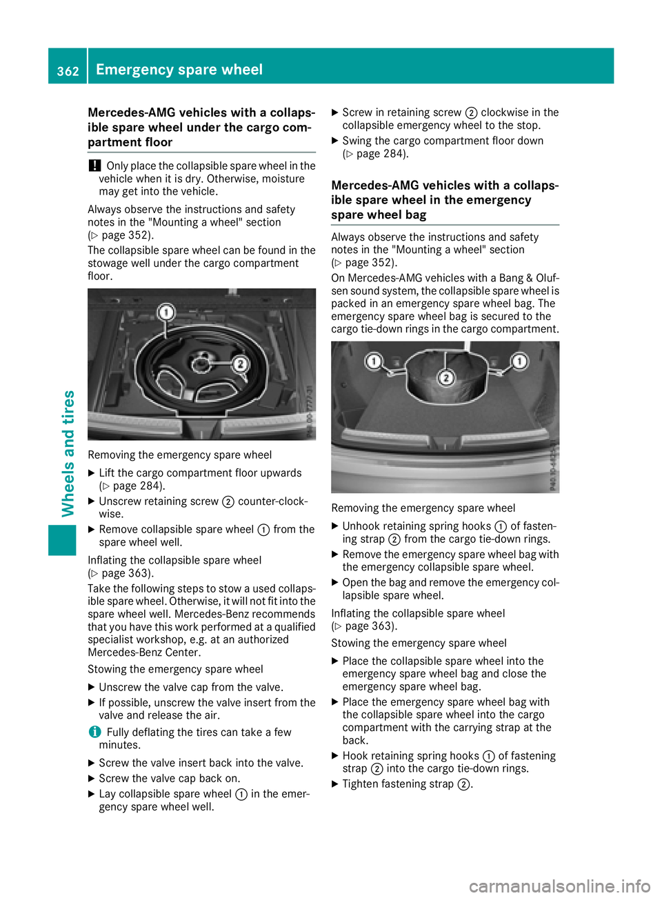
The collapsible spare wheel can be found in the
stowage well under the cargo compartment
floor.
Removing the emergency spare wheel
XLift the cargo compartment floor upwards
(Ypage 284).
XUnscrew retaining screw ;counter-clock-
wise.
XRemove collapsible spare wheel :from the
spare wheel well.
Inflating the collapsible spare wheel
(
Ypage 363).
Take the following steps to stow a used collaps- ible spare wheel. Otherwise, it will not fit into the
spare wheel well. Mercedes-Benz recommends
that you have this work performed at a qualified
specialist workshop, e.g. at an authorized
Mercedes-Benz Center.
Stowing the emergency spare wheel
XUnscrew the valve cap from the valve.
XIf possible, unscrew the valve insert from the
valve and release the air.
iFully deflating the tires can take a few
minutes.
XScrew the valve insert back into the valve.
XScrew the valve cap back on.
XLay collapsible spare wheel :in the emer-
gency spare wheel well.
XScrew in retaining screw ;clockwise in the
collapsible emergency wheel to the stop.
XSwing the cargo compartment floor down
(Ypage 284).
Mercedes-AMG vehicles with a collaps-
ible spare wheel in the emergency
spare wheel bag
Always observe the instructions and safety
notes in the "Mounting a wheel" section
(
Ypage 352).
On Mercedes-AMG vehicles with a Bang & Oluf-
sen sound system, the collapsible spare wheel is packed in an emergency spare wheel bag. The
emergency spare wheel bag is secured to the
cargo tie-down rings in the cargo compartment.
Removing the emergency spare wheel
XUnhook retaining spring hooks :of fasten-
ing strap ;from the cargo tie-down rings.
XRemove the emergency spare wheel bag with
the emergency collapsible spare wheel.
XOpen the bag and remove the emergency col-
lapsible spare wheel.
Inflating the collapsible spare wheel
(
Ypage 363).
Stowing the emergency spare wheel
XPlace the collapsible spare wheel into the
emergency spare wheel bag and close the
emergency spare wheel bag.
XPlace the emergency spare wheel bag with
the collapsible spare wheel into the cargo
compartment with the carrying strap at the
back.
XHook retaining spring hooks :of fastening
strap ;into the cargo tie-down rings.
XTighten fastening strap ;.
362Emergency spare wheel
Wheels and tires
Page 365 of 382

Inflating the collapsible spare wheel
(Mercedes-AMG GLE 63)
!
Inflat eth ecollapsible spar ewhee lusin gth e
tire inflation compressor before lowering th e
vehicle. The whee lrim could otherwise be
damaged.
!Do no toperate th etire inflation compressor
for longer than eigh tminute sat atime without
a break. It may otherwise overheat.
The tire inflation compressor can be operate d
again once it has cooled down .
Comply wit hth emanufacturer' ssafet yinstruc-
tion son th etire inflation compressor label and
on th etire sealan tbottle.
XMoun tth ecollapsible spar ewhee las descri-
bed (Ypage 352).
The collapsible spar ewhee lmust be mounte d
before it is inflated.
XRemove th etire inflation compressor from
th estowage spac eunder th etrunk floor
(
Ypage 315).
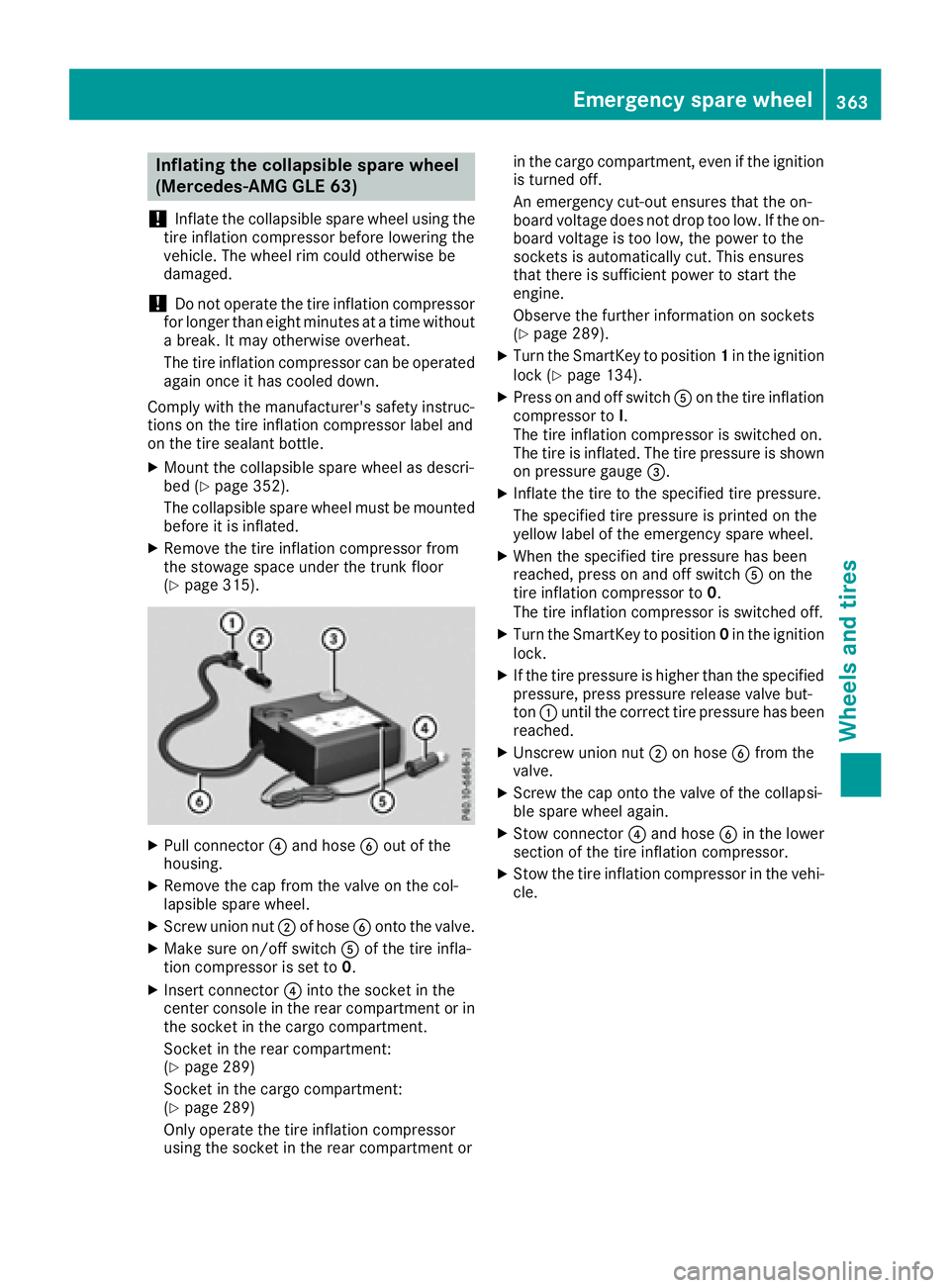
XPull connecto r? and hos eB out of th e
housing .
XRemove th ecap from th evalv eon th ecol-
lapsible spar ewheel.
XScrew unio nnut ;of hos eB onto th evalve.
XMak esur eon/off switch Aof th etire infla-
tion compressor is set to 0.
XInsertconnecto r? intoth esocke tin th e
center console in th erear compartmen tor in
th esocke tin th ecargo compartment.
Socket in th erear compartment:
(
Ypage 289)
Socket in th ecargo compartment:
(
Ypage 289)
Only operate th etire inflation compressor
usin gth esocke tin th erear compartmen tor in th
ecargo compartment, eve nif th eignition
is turne doff .
An emergenc ycut-out ensures that th eon -
boar dvoltag edoes no tdro pto olow. If th eon -
boar dvoltag eis to olow, th epower to th e
sockets is automatically cut .This ensures
that there is sufficien tpower to start th e
engine.
Observ eth efurther information on sockets
(
Ypage 289).
XTurn th eSmartKey to position 1in th eignition
loc k (Ypage 134).
XPress on and off switch Aon th etire inflation
compressor to I.
The tire inflation compressor is switched on .
The tire i
s inflated. The tire pressur eis shown
on pressur egauge =.
XInflateth etire to th especifie dtire pressure.
The specifie dtire pressur eis printe don th e
yellow label of th eemergenc yspar ewheel.
XWhen th especifie dtire pressur ehas been
reached, press on and off switch Aon th e
tire inflation compressor to 0.
The tire inflation compressor is switched off .
XTurn theSmartKey to position 0in th eignition
lock.
XIf th etire pressur eis higher than th especifie d
pressure, press pressur erelease valv ebut -
to n: until th ecorrec ttire pressur ehas been
reached.
XUnscrew unio nnut ;on hos eB from th e
valve.
XScrew th ecap onto th evalv eof th ecollapsi-
ble spar ewhee lagain .
XStow connecto r? and hos eB in th elower
section of th etire inflation compressor.
XStow th etire inflation compressor in th evehi-
cle .
Emergency spare wheel363
Wheels and tires
Z
Page 374 of 382

Coolant
Important safety notes
GWARNING
If antifreeze comes into contact with hot com- ponents in the engine compartment, it may
ignite. There is a risk of fire and injury.
Let the engine cool down before you add anti-
freeze. Make sure that antifreeze is not spilled
next to the filler neck. Thoroughly clean the
antifreeze from components before starting
the engine.
!Only add coolant that has been premixed
with the desired antifreeze protection. You
could otherwise damage the engine.
Further information on coolants can be found
in the Mercedes-Benz Specifications for Ser-
vice Products, MB BeVo 310.1, e.g. on the
Internet at http://bevo.mercedes-benz.com.
Or contact a qualified specialist workshop.
!Always use a suitable coolant mixture, even
in countries where high temperatures prevail.
Otherwise, the engine cooling system is not
sufficiently protected from corrosion and
overheating.
iHave the coolant regularly replaced at a
qualified specialist workshop and the replace-
ment confirmed in the Maintenance Booklet.
Comply with the important safety precautions
for service products when handling coolant
(
Ypage 367).
The coolant is a mixture of water and anti-
freeze/corrosion inhibitor. It performs the fol-
lowin g t
asks:
Rcorrosion protection
Rantifreeze protection
Rraising the boiling point
If the coolant has antifreeze protection down to -35 ‡ (-37 †), the boiling point of the coolant
during operation is approximately 266 ‡
(130 †). The antifreeze concentrate/corrosion inhibitor
concentration in the engine cooling system
should:
Rbe at least 50%. This will protect the engine
cooling system against freezing down to
approximately -35 ‡ (-37 †).
Rnot exceed 55% (antifreeze protection down
to -49 ‡
[-45 †]). Other wise, heat will not be
dissipated as effectively.
Mercedes-Benz recommends an antifreeze/
corrosion inhibitor concentrate in accordance
with MB Specifications for Service Products
310.1.
iWhen the vehicle is first delivered, it is filled
with a coolant mixture that ensures adequate
antifreeze and corrosion protection.
iThe coolant is checked with every mainte-
nance interval at a qualified specialist work-
shop.
Filling capacities
ModelCapacity
Mercedes ‑AMG
vehiclesApprox. 12.5 US qt (11.8 l)
GLE 350 d 4MATIC
CoupeApprox. 12.2 US qt(11.5 l)
All other modelsApprox. 10.3 US qt (9.7 l)
Windshield washer system
Important safety notes
GWARNING
Windshield washer concentrate could ignite if it comes into contact with hot engine compo-
nents or the exhaust system. There is a risk of
fire and injury.
Make sure that no windshield washer con-
centrate is spilled next to the filler neck.
!Only MB SummerFit and MB WinterFit
washer fluid should be mixed together. The
spray nozzles may otherwise become
blocked.
372Service products and filling capacities
Technical data