2016 MERCEDES-BENZ GLE-CLASS COUPE emergency towing
[x] Cancel search: emergency towingPage 11 of 382
Deactivating/activating ................. 139
General information ....................... 138
Important safety notes .................. 138
Introduction ................................... 138
Emergency
Automatic measures after an acci-
dent ................................................. 53
Emergency release
Driver's door .................................... 80
Vehicle ............................................. 80
Emergency spare wheel
General notes ................................ 360
Important safety notes .................. 360
Removing ....................................... 361
Storage location ............................ 361
Stowing .......................................... 361
Technical data ............................... 364
Emergency Tensioning Devices
Activation ......................................... 50
Emergency unlocking
Tailgate ............................................ 85
Emissions control
Service and warranty information .... 23
Engine
Check Engine warning lamp ........... 274
Display message ............................ 249
ECO start/stop function ................ 138
Engine number ............................... 367
Irregular running ............................ 141
Jump-starting ................................. 323
Starting (important safety notes) ... 136
Starting problems .......................... 141
Starting the engine with the
SmartKey ....................................... 136
Starting via smartphone ................ 136
Starting with KEYLESS-GO ............. 136
Switching off .................................. 157
Tow-starting (vehicle) ..................... 327
Engine electronics
Problem (malfunction) ................... 141
Engine oil
Adding ........................................... 304
Additives ........................................ 371
Checking the oil level ..................... 303
Checking the oil level using the
dipstick .......................................... 303
Display message ............................ 251
Filling capacity ............................... 371 Notes about oil grades ................... 370
Notes on oil level/consumption .... 303
Temperature (on-board computer,
Mercedes-AMG vehicles) ............... 231
Viscosity ........................................ 371
ESP
®(Electronic Stability Pro-
gram)
AMG menu (on-board computer) ... 232
Characteristics ................................. 66
Deactivating/activating ................... 66
Display message ............................ 235
Function/notes ................................ 65
General notes .................................. 65
Important safety information ........... 65
Trailer stabilization ........................... 67
Warning lamp ................................. 270
ETS/4ETS (Electronic Traction Sys-
tem) ...................................................... 65
Exhaust check ................................... 160
Exhaust pipe (cleaning instruc-
tions) .................................................. 312
Exterior mirrors
Adjusting ....................................... 104
Dipping (automatic) ....................... 105
Folding in when locking (on-board
computer) ...................................... 231
Folding in/out (automatically) ....... 105
Folding in/out (electrically) ........... 105
Out of position (troubleshooting) ... 105
Setting ........................................... 105
Storing settings (memory func-
tion) ............................................... 107
Storing the parking position .......... 106
Eyeglasses compartment ................. 280
F
Filler cap
see Refueling
Flat tire
MOExtended tires .......................... 316
Preparing the vehicle ..................... 315
TIREFIT kit ...................................... 317
see Emergency spare wheel
Floormats ........................................... 301
Folding the rear bench seat for-
wards/back ....................................... 281
Index9
Page 21 of 382

Uniform Tire Quality Grading
Standards (definition) .................... 349
Wear indicator (definition) .............351
Wheel and tire combination ........... 357
Wheel rim (definition) .................... 349
see Flat tire
Top Tether ............................................ 56
Tow-starting
Emergency engine starting ............ 327
Important safety notes .................. 325
Towing a trailer
Axle load, permissible .................... 376
Cleaning the trailer tow hitch ......... 312
Coupling up a trailer ......................2 15
Decoupling a trailer ....................... 216
Driving tips ....................................2 12
ESP
®(Electronic Stability Pro-
gram) ............................................... 67
Important safety notes .................. 212
Installing the ball coupling ............. 213
Lights display message .................. 246
Mounting dimensions .................... 376
Power supply ................................. 217
Pulling away with a trailer .............. 138
Removing the ball coupling ............ 217
Trailer loads ................................... 376
Towing away
Important safety guidelines ........... 325
Installing the towing eye ................ 326
Notes for 4MATIC vehicles ............ 327
Removing the towing eye ...............3 26
Transporting the vehicle ................ 327
With both axles on the ground ....... 326
Towing eye ......................................... 315
Traffic Sign Assist
Display message ............................ 254
Function/notes .............................2 02
Important safety notes .................. 202
Instrument cluster display ............. 202
Trailer coupling
see Towing a trailer
Trailer loads and drawbar nose-
weights ............................................... 217
Trailer towing
Active Blind Spot Assist ................. 209
Active Lane Keeping Assist ............ 211
Blind Spot Assist ............................ 205 PARKTRONIC ................................. 186
Permi
ssibl
e trailer loads and
drawbar noseweights ..................... 217
Transfer case ..................................... 150
Transmission
see Automatic transmission
Transmission position display ......... 143
Transmission position display
(DIRECT SELECT lever) ......................143
Transporting the vehicle .................. 327
Traveling uphill
Brow of hill ..................................... 168
Driving downhill .............................1 68
Maximum gradient-climbing capa-
bility ............................................... 168
Trim pieces (cleaning instruc-
tions) ..................................................3 13
Trip computer (on-board com-
puter) ..................................................2 22
Trip odometer
Calling up ....................................... 222
Resetting (on-board computer) ...... 223
Trunk
see Tailgate
Trunk load (maximum) ......................373
Turn signals
Display message ............................ 246
Switching on/off ........................... 110
Two-way radio
Frequencies ................................... 365
Installation ..................................... 365
Transmission output (maximum) .... 365
TWR (Tongue Weight Rating) (defi-
nition) ................................................. 351
Type identification plate
see Vehicle identification plate
U
UnlockingEmergency unlocking ....................... 80
From inside the vehicle (central
unlocking button) .............................7 9
Upshift indicator (on-board com-
puter, Mercedes-AMG vehicles) .......231
Index19
Page 22 of 382
V
Vanity mirror (in the sun visor)........ 287
Vehicle
Correct use ...................................... 26
Data acquisition ............................... 27
Display message ............................ 261
Equipment ....................................... 23
Individual settings .......................... 229
Limited Warranty ............................. 27
Loading .......................................... 340
Locking (in an emergency) ............... 80
Locking (SmartKey) .......................... 72
Lowering ........................................ 355
Maintenance .................................... 24
Parking for a long period ................ 159
Pulling away ................................... 137
Raising ........................................... 353
Reporting problems ......................... 26
Securing from rolling away ............ 352
Towing away .................................. 325
Transporting .................................. 327
Unlocking (in an emergency) ........... 80
Unlocking (SmartKey) ...................... 72
Vehicle data ................................... 373
Vehicle data
Roof load (maximum) ..................... 373
Trunk load (maximum) ................... 373
Vehicle data (off-road driving)
Approach/departure angle ............ 375
Fording depth ................................ 375
Maximum gradient climbing abil-
ity .................................................. 376
Vehicle dimensions ........................... 373
Vehicle emergency locking ................ 80
Vehicle identification number
see VIN
Vehicle identification plate .............. 366
Vehicle level
AIRMATIC ...................................... 183
Vehicle level (display message) ....... 253
Vehicle tool kit .................................. 315
Video
Operating the DVD ......................... 225
VIN ...................................................... 366
Seat ............................................... 367
Type plate ...................................... 366
W
Warning and indicator lamps ABS ................................................ 268
Brakes ........................................... 267
Check Engine ................................. 274
Coolant .......................................... 274
Distance warning ........................... 276
DISTRONIC PLUS ........................... 276
ESP
®.............................................. 270
ESP®OFF ....................................... 271
Fuel tank ........................................ 274
Overview .......................................... 32
Parking brake ................................ 273
PASSENGER AIR BAG ...................... 39
Reserve fuel ................................... 274
Restraint system ............................ 273
Seat belt ........................................ 265
Tire pressure monitor .................... 277
Warranty .............................................. 23
Washer fluid
Display message ............................ 263
Wheel and tire combination
see Tires
Wheel bolt tightening torque ........... 355
Wheel chock ...................................... 352
Wheels
Changing a wheel .......................... 351
Checking ........................................ 331
Cleaning ......................................... 310
Emergency spare wheel ................. 360
General notes ................................ 356
Important safety notes .................. 330
Information on driving .................... 330
Interchanging/changing ................ 351
Mounting a new wheel ................... 354
Mounting a wheel .......................... 352
Overview ........................................ 330
Removing a wheel .......................... 354
Storing ........................................... 352
Tightening torque ........................... 355
Wheel size/tire size ....................... 356
Window curtain air bag
Display message ............................ 243
Operation ......................................... 45
Windows
see Side windows
20Index
Page 295 of 382
lished between the Customer Assistance Center
and the vehicle occupants.
RIf the vehicle occupants respond, the
Mercedes-Benz Customer Assistance Center
attempts to get more information on the
emergency.
RIf there is no response from the vehicle occu-pants, an ambulance is immediately sent to
the vehicle.
If no voice connection can be established to the
Mercedes-Benz Customer Assistance Center,
the system has been unable to initiate an emer-
gency call.
This can occur, for example, if the relevant
mobile phone network is not available. The indi-
cator lamp in the SOS button flashes continu-
ously.
The Call Failed
message appears in the mul-
tifunction display and must be confirmed.
In this case, summon assistance by other
means.
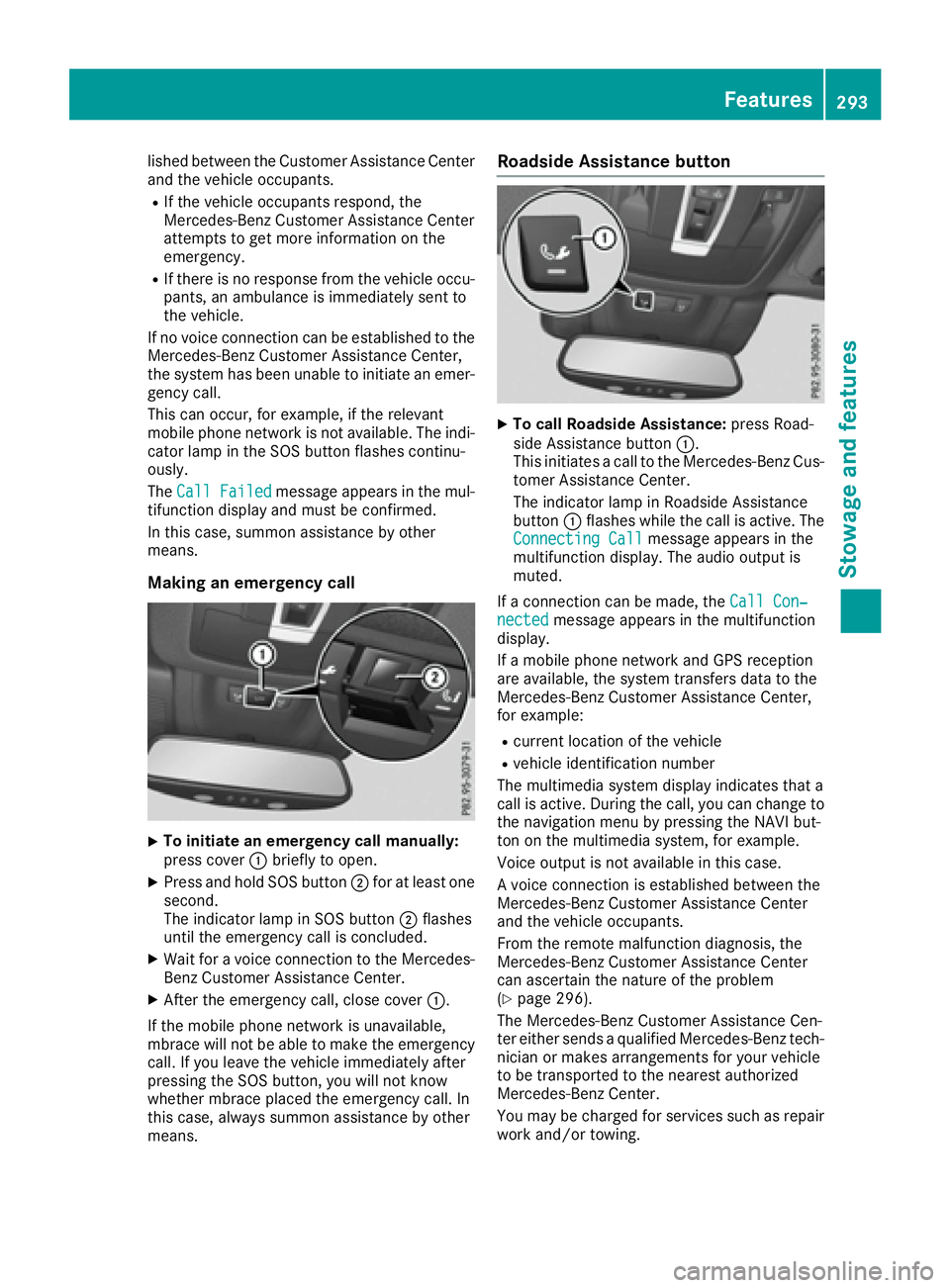
Making an emergency call
XTo initiate an emergency call manually:
press cover :briefly to open.
XPress and hold SOS button ;for at least one
second.
The indicator lamp in SOS button ;flashes
until the emergency call is concluded.
XWait for a voice connection to the Mercedes-
Benz Customer Assistance Center.
XAfter the emergency call, close cover :.
If the mobile phone network is unavailable,
mbrace will not be able to make the emergency
call. If you leave the vehicle immediately after
pressing the SOS button, you will not know
whether mbrace placed the emergency call. In
this case, always summon assistance by other
means.
Roadside Assistance button
XTo call Roadside Assistance: press Road-
side Assistance button :.
This initiates a call to the Mercedes-Benz Cus-
tomer Assistance Center.
The indicator lamp in Roadside Assistance
button :flashes while the call is active. The
Connecting Call
message appears in the
multifunction display. The audio output is
muted.
If a connection can be made, the Call Con‐
nectedmessage appears in the multifunction
display.
If a mobile phone network and GPS reception
are available, the system transfers data to the
Mercedes-Benz Customer Assistance Center,
for example:
Rcurrent location of the vehicle
Rvehicle identification number
The multimedia system display indicates that a
call is active. During the call, you can change to
the navigation menu by pressing the NAVI but-
ton on the multimedia system, for example.
Voice output is not available in this case.
A voice connection is established between the
Mercedes-Benz Customer Assistance Center
and the vehicle occupants.
From the remote malfunction diagnosis, the
Mercedes-Benz Customer Assistance Center
can ascertain the nature of the problem
(
Ypage 296).
The Mercedes-Benz Customer Assistance Cen-
ter either sends a qualified Mercedes-Benz tech-
nician or makes arrangements for your vehicle
to be transported to the nearest authorized
Mercedes-Benz Center.
You may be charged for services such as repair
work and/or towing.
Features293
Stowage and features
Z
Page 317 of 382
Useful information
i
This Operator's Manual describes all models
and all standard and optional equipment of
your vehicle available at the time of publica-
tion of the Operator's Manual. Country-spe-
cific differences are possible. Please note
that your vehicle may not be equipped with all
features described. This also applies to
safety-related systems and functions.
iRead the information on qualified specialist
workshops (Ypage 26).
Where will I find...?
Vehicle tool kit
General notes
The vehicle tool kit can be found in the stowage
well under the cargo compartment floor.
Apart from certain country-specific variations,
the vehicles are not equipped with a tire-change
tool kit. Some tools for changing a wheel are
specific to the vehicle. For more information on which tools are required to perform a wheel
change on your vehicle, consult a qualified spe-
cialist workshop.
Tools required for changing a wheel may
include, for example:
RJack
RWheel chock
RLug wrench
RRatchet wrench
RAlignment bolt
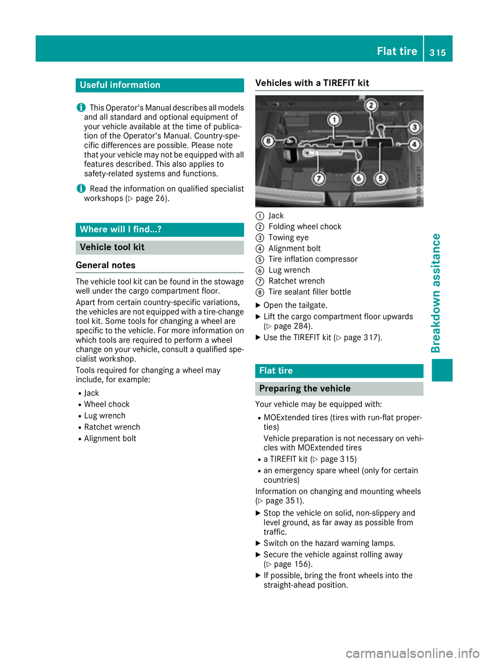
Vehicles with a TIREFIT kit
:Jack
;Folding wheel chock
=Towing eye
?Alignment bolt
ATire inflation compressor
BLug wrench
CRatchet wrench
DTire sealant filler bottle
XOpen the tailgate.
XLift the cargo compartment floor upwards
(Ypage 284).
XUse the TIREFIT kit (Ypage 317).
Flat tire
Preparing the vehicle
Your vehicle may be equipped with:
RMOExtended tires (tires with run-flat proper-
ties)
Vehicle preparation is not necessary on vehi-
cles with MOExtended tires
Ra TIREFIT kit (Ypage 315)
Ran emergency spare wheel (only for certain
countries)
Information on changing and mounting wheels
(
Ypage 351).
XStop the vehicle on solid, non-slippery and
level ground, as far away as possible from
traffic.
XSwitch on the hazard warning lamps.
XSecure the vehicle against rolling away
(Ypage 156).
XIf possible, bring the front wheels into the
straight-ahead position.
Flat tire315
Breakdown assitance
Page 329 of 382
In order to ensure that the automatic transmis-
sion stays in positionNwhen towing the vehicle,
you must observe the following points:
XMake sure that the vehicle is stationary.
XTurn the SmartKey to position 2in the ignition
lock.
XDepress and hold the brake pedal.
XShift the automatic transmission to position
N.
XLeave the SmartKey in position 2in the igni-
tion lock.
XRelease the brake pedal.
XRelease the electric parking brake.
XSwitch on the hazard warning lamps
(Ypage 110).
In order to signal a change of direction when
towing the vehicle with the hazard warning
lamps switched on, use the combination switch
as usual. In this case, only the indicator lamps
for the direction of travel flash. After resetting
the combination switch, the hazard warning
lamp starts flashing again.
Transporting the vehicle
4MATIC vehicles/vehicles with auto-
matic transmission
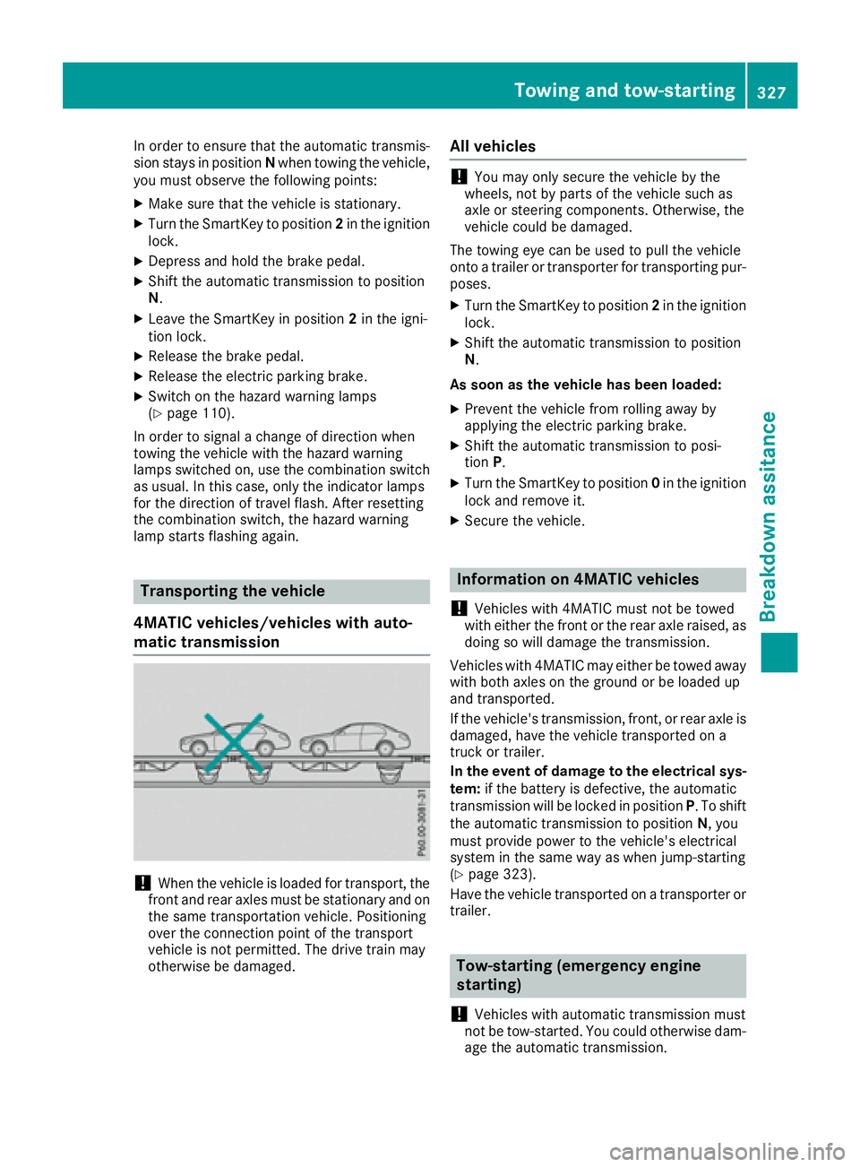
!When the vehicle is loaded for transport, the
front and rear axles must be stationary and on the same transportation vehicle. Positioning
over the connection point of the transport
vehicle is not permitted. The drive train may
otherwise be damaged.
All vehicles
!You may only secure the vehicle by the
wheels, not by parts of the vehicle such as
axle or steering components. Otherwise, the
vehicle could be damaged.
The towing eye can be used to pull the vehicle
onto a trailer or transporter for transporting pur-
poses.
XTurn the SmartKey to position 2in the ignition
lock.
XShift the automatic transmission to position
N.
As soon as the vehicle has been loaded:
XPrevent the vehicle from rolling away by
applying the electric parking brake.
XShift the automatic transmission to posi-
tion P.
XTurn the SmartKey to position 0in the ignition
lock and remove it.
XSecure the vehicle.
Information on 4MATIC vehicles
!
Vehicles with 4MATIC must not be towed
with either the front or the rear axle raised, as
doing so will damage the transmission.
Vehicles with 4MATIC may either be towed away with both axles on the ground or be loaded up
and transported.
If the vehicle's transmission, front, or rear axle is
damaged, have the vehicle transported on a
truck or trailer.
In the event of damage to the electrical sys-
tem: if the battery is defective, the automatic
transmission will be locked in position P. To shift
the automatic transmission to position N, you
must provide power to the vehicle's electrical
system in the same way as when jump-starting
(
Ypage 323).
Have the vehicle transported on a transporter or
trailer.
Tow-starting (emergency engine
starting)
!
Vehicles with automatic transmission must
not be tow-started. You could otherwise dam-
age the automatic transmission.
Towing and tow-starting327
Breakdown assitance
Z
Page 363 of 382

Replaceth etires after six years at th elatest ,
regardless of wear .This also applie sto th e
emergenc yspar ewheel.
iWhen you are driving wit hth ecollapsible
spar ewhee lmounted, th etire pressur eloss
warning system or th etire pressur emonitor
canno tfunction reliably. Only restar tth etire
pressur eloss warning system or tire pressur e
monitor when th edefective whee lhas been
replace dwit h a newwheel.
Vehicles with tire pressure monitor: after
mounting an emergenc yspar ewheel, th esys-
te m may still display th etire pressur eof th e
remove dwhee lfor afew minutes. The value
displayed for th emounte demergenc yspar e
whee lis no tth esam eas th ecurren ttire pres-
sur eof th eemergenc yspar ewheel.
Removing/stowing the emergency
spare wheel
Vehicles with a "Minispare" emergency
spare wheel under the cargo compart-
ment floor
Always observ eth einstruction sand safet y
note sin th e"Mounting awheel" section
(
Ypage 352).
The "Minispare" emergenc yspar ewhee lcan be
foun din th estowage well under th ecargo com-
partmen tfloor.
Removin gth eemergenc yspar ewhee l
XLiftth ecargo compartmen tfloor upwards
(Ypage 284).
XTurn retaining screw ;counter-clockwise
and remove it .
XRemove "Minispare" emergenc yspar e
whee l:.
Vehicles with a "Minispare" emergency
spare wheel in the emergency spare
wheel bag
Always observ eth einstruction sand safet y
note sin th e"Mounting awheel" section
(
Ypage 352).
On vehicles wit h aBan g & Olufsen soun dsys-
tem, th e"Minispare" emergenc yspar ewhee lis
packe din an emergenc yspar ewhee lbag. The
emergenc yspar ewhee lbag is secured to th e
cargo tie-down rings in th ecargo compartment.
Removin gth eemergenc yspar ewhee l
XDetac hfastenin gstraps ;.
XUnhookretaining spring hooks :and =of
fastenin gstraps ;from th ecargo tie-down
rings.
XRemove th eemergenc yspar ewhee lbag wit h
th e"Minispare" emergenc yspar ewheel.
XOpen th eemergenc yspar ewhee lbag and
remove th e"Minispare" emergenc yspar e
wheel.
Stowin gth eemergenc yspar ewhee l
XPlaceth e"Minispare" emergenc yspar ewhee l
int oth eemergenc yspar ewhee lbag and
close th eemergenc yspar ewhee lbag.
XPlac eth eemergenc yspar ewhee lbag wit h
th e"Minispare" emergenc yspar ewhee lint o
th ecargo compartmen twit hth ecarryin g
strap at th eback.
XHook retaining spring hooks :and =of
fastenin gstraps ;intoth ecargo tie-down
rings.
XTighte nfastenin gstraps ;.
Emergency spare wheel361
Wheels and tires
Z
Page 364 of 382
Mercedes-AMG vehicles with a collaps-
ible spare wheel under the cargo com-
partment floor
!Only place the collapsible spare wheel in the
vehicle when it is dry. Otherwise, moisture
may get into the vehicle.
Always observe the instructions and safety
notes in the "Mounting a wheel" section
(
Ypage 352).
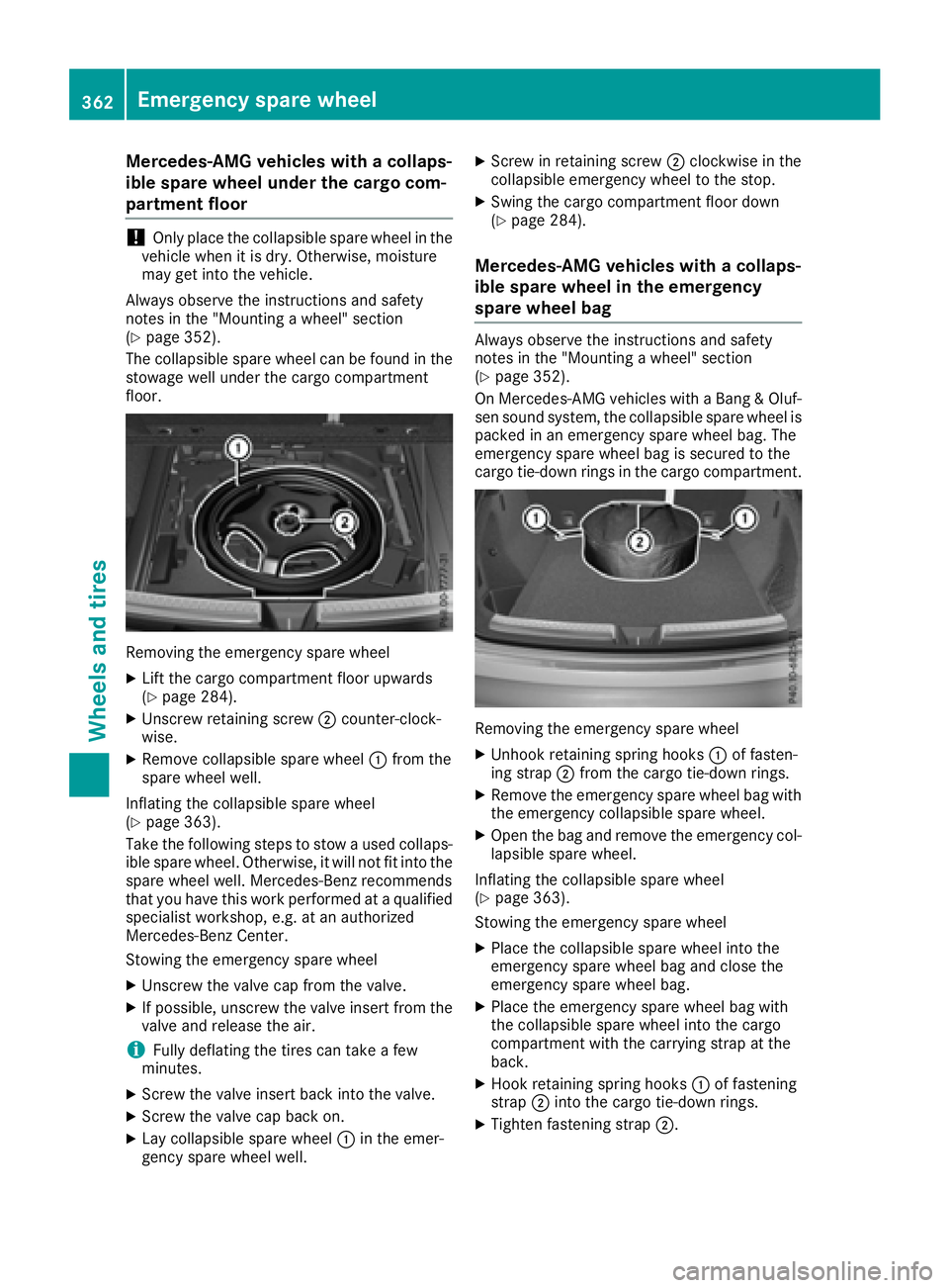
The collapsible spare wheel can be found in the
stowage well under the cargo compartment
floor.
Removing the emergency spare wheel
XLift the cargo compartment floor upwards
(Ypage 284).
XUnscrew retaining screw ;counter-clock-
wise.
XRemove collapsible spare wheel :from the
spare wheel well.
Inflating the collapsible spare wheel
(
Ypage 363).
Take the following steps to stow a used collaps- ible spare wheel. Otherwise, it will not fit into the
spare wheel well. Mercedes-Benz recommends
that you have this work performed at a qualified
specialist workshop, e.g. at an authorized
Mercedes-Benz Center.
Stowing the emergency spare wheel
XUnscrew the valve cap from the valve.
XIf possible, unscrew the valve insert from the
valve and release the air.
iFully deflating the tires can take a few
minutes.
XScrew the valve insert back into the valve.
XScrew the valve cap back on.
XLay collapsible spare wheel :in the emer-
gency spare wheel well.
XScrew in retaining screw ;clockwise in the
collapsible emergency wheel to the stop.
XSwing the cargo compartment floor down
(Ypage 284).
Mercedes-AMG vehicles with a collaps-
ible spare wheel in the emergency
spare wheel bag
Always observe the instructions and safety
notes in the "Mounting a wheel" section
(
Ypage 352).
On Mercedes-AMG vehicles with a Bang & Oluf-
sen sound system, the collapsible spare wheel is packed in an emergency spare wheel bag. The
emergency spare wheel bag is secured to the
cargo tie-down rings in the cargo compartment.
Removing the emergency spare wheel
XUnhook retaining spring hooks :of fasten-
ing strap ;from the cargo tie-down rings.
XRemove the emergency spare wheel bag with
the emergency collapsible spare wheel.
XOpen the bag and remove the emergency col-
lapsible spare wheel.
Inflating the collapsible spare wheel
(
Ypage 363).
Stowing the emergency spare wheel
XPlace the collapsible spare wheel into the
emergency spare wheel bag and close the
emergency spare wheel bag.
XPlace the emergency spare wheel bag with
the collapsible spare wheel into the cargo
compartment with the carrying strap at the
back.
XHook retaining spring hooks :of fastening
strap ;into the cargo tie-down rings.
XTighten fastening strap ;.
362Emergency spare wheel
Wheels and tires