2016 MERCEDES-BENZ GLA diagnostic menu
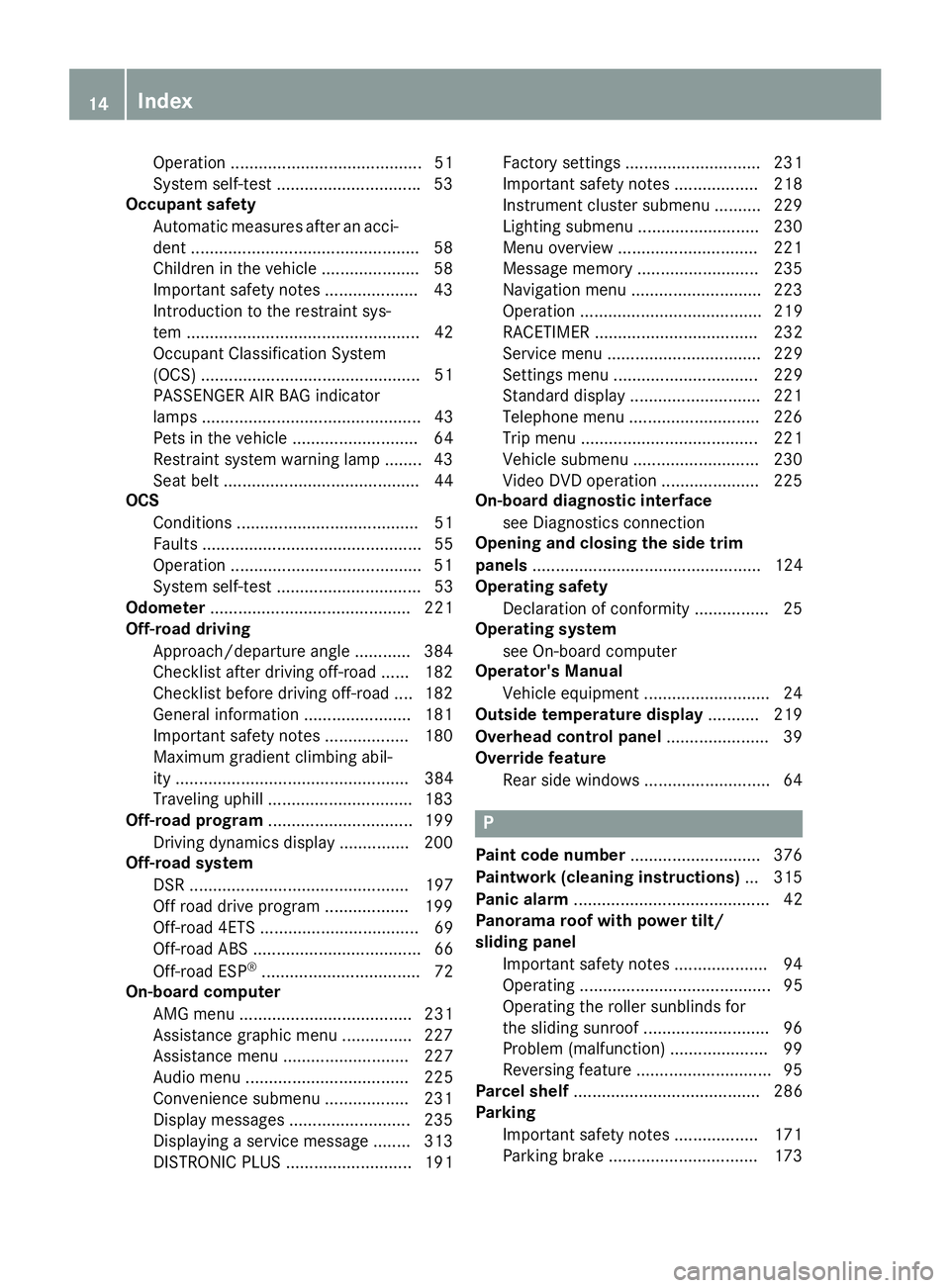
[x] Cancel search: diagnostic menuPage 16 of 390

Operation ......................................... 51
System self-test .............................. .5 3
Occupant safety
Automatic measures after an acci-
dent ................................................ .5 8
Childr en in the vehicle .................... .5 8
Important safety notes .................... 43
Introduction to the restraint sys-
tem .................................................. 42
Occupant Classification System
(OCS) ............................................... 51
PASSENGER AIR BAG indicator
lamps ............................................... 43
Pets in the vehicle ........................... 64
Restraint system warning lamp ........ 43
Seat belt .......................................... 44
OCS
Conditions ....................................... 51
Faults ............................................... 55
Operation ........................................ .5 1
System self-test ............................... 53
Odometer ........................................... 221
Off-road driving
Approach/departure angle ............ 384
Checklist after driving off-road ...... 182
Checklist before driving off-road .... 182
General information ....................... 181
Important safety notes .................. 180
Maximum gradient climbing abil-
ity .................................................. 384
Traveling uphill ............................... 183
Off-road program ............................... 199
Driving dynamics display ............... 200
Off-road system
DSR ............................................... 197
Off road drive program .................. 199
Off-road 4ETS .................................. 69
Off-road ABS .................................... 66
Off-road ESP ®
.................................. 72
On-board computer
AMG menu ..................................... 231
Assistance graphic menu ............... 227
Assistance menu ........................... 227
Audio menu ................................... 225
Convenience submenu .................. 231
Display messages .......................... 235
Displayi ng a se rvice message ........ 313
DISTRONIC
PLUS ........................... 191 Factory settings ............................. 231
Important safety notes .................. 218
Instrument cluster submenu .......... 229
Lighting submenu .......................... 230
Menu overview .............................. 221
Message memory .......................... 235
Navigation menu ............................ 223
Operation ....................................... 219
RACETIMER ................................... 232
Service menu ................................. 229
Settings menu ............................... 229
Standard display ............................ 221
Telephone menu ............................ 226
Trip menu ...................................... 221
Vehicle submenu ........................... 230
Video DVD operation ..................... 225
On-board diagnostic interface
see Diagnostics connection
Opening and closing the side trim
panels ................................................. 124
Operating safety
Declaration of conformity ................ 25
Operating system
see On-board computer
Operator's Manual
Vehicle equipment ........................... 24
Outside temperature display ........... 219
Overhead control panel ...................... 39
Override feature
Rear side windows ........................... 64
P
Paint code number ............................ 376
Paintwork (cleaning instructions) ... 315
Panic alarm .......................................... 42
Panorama roof with power tilt/
sliding panel
Important safety notes .................... 94
Operating ......................................... 95
Operating the roller sunblinds for
the sliding sunroof ........................... 96
Problem (malfunction) ..................... 99
Reversing feature ............................. 95
Parcel shelf ........................................ 286
Parking
Important safety notes .................. 171
Parking brake ................................ 17314
Index
Page 301 of 390

If vehicle data needs to be transferred during
an MB Info call or a Roadside Assistance call,
this is initiated by the Customer Assistance
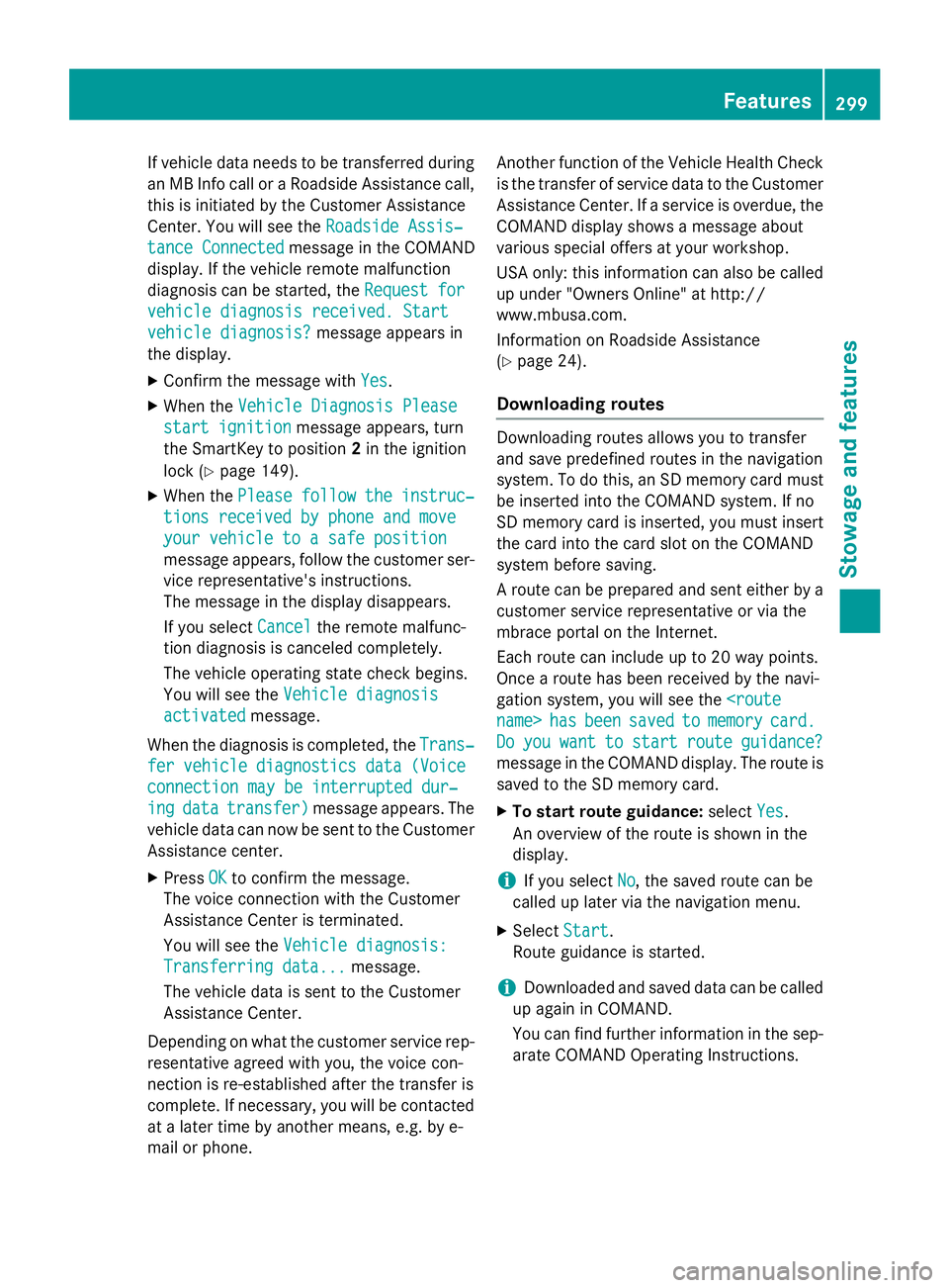
Center. You will see the Roadside Assis‐
tance Connected message in the COMAND
display. If the vehicle remote malfunction
diagnosis can be started, the Request for
vehicle diagnosis received. Start
vehicle diagnosis? message appears in
the display. X
Confirm the message with Yes .X
When the Vehicle Diagnosis Please
start ignition message appears, turn
the SmartKey to position 2 in the ignition
lock ( Y
page 149).X
When the Please follow the instruc‐
tions received by phone and move
your vehicle to a safe position
message appears, follow the customer ser-
vice representative's instructions.
The message in the display disappears.
If you select Cancel the remote malfunc-
tion diagnosis is canceled completely.
The vehicle operating state check begins.
You will see the Vehicle diagnosis
activated message.
When the diagnosis is completed, the Trans‐
fer vehicle diagnostics data (Voice
connection may be interrupted dur‐
ing data transfer) message appears. The
vehicle data can now be sent to the Customer
Assistance center. X
Press OK to confirm the message.
The voice connection with the Customer
Assistance Center is terminated.
You will see the Vehicle diagnosis:
Transferring data... message.
The vehicle data is sent to the Customer
Assistance Center.
Depending on what the customer service rep-
resentative agreed with you, the voice con-
nection is re-established after the transfer is
complete. If necessary, you will be contacted
at a later time by another means, e.g. by e-
mail or phone. Another function of the Vehicle Health Check
is the transfer of service data to the Customer
Assistance Center. If a service is overdue, the
COMAND display shows a message about
various special offers at your workshop.
USA only: this information can also be called
up under "Owners Online" at http://
www.mbusa.com.
Information on Roadside Assistance
( Y
page 24).
Downloading routes Downloading routes allows you to transfer
and save predefined routes in the navigation
system. To do this, an SD memory card must
be inserted into the COMAND system. If no
SD memory card is inserted, you must insert
the card into the card slot on the COMAND
system before saving.
A route can be prepared and sent either by a
customer service representative or via the
mbrace portal on the Internet.
Each route can include up to 20 way points.
Once a route has been received by the navi-
gation system, you will see the
Do you want to start route guidance?
message in the COMAND display. The route is
saved to the SD memory card. X
To start route guidance: select Yes .
An overview of the route is shown in the
display.
i If you select No , the saved route can be
called up later via the navigation menu. X
Select Start .
Route guidance is started.
i Downloaded and saved data can be called
up again in COMAND.
You can find further information in the sep-
arate COMAND Operating Instructions. Features 299
Stowage and features Z