2016 MERCEDES-BENZ G-Class spare wheel
[x] Cancel search: spare wheelPage 16 of 302

Service menu (on-board com-
puter).................................................. 178
Service products
Brake fluid .....................................2 93
Coolant (engine) ............................ 294
Engine oil ....................................... 292
Fuel ................................................ 289
Important safety notes .................. 289
Notes ............................................. 289
Refrigerant (air-conditioning sys-
tem) ............................................... 293
Washer fluid ................................... 295
Setting a speed limit
see SPEEDTRONIC
Setting the air distribution ...............105
Settings
Calling up a stored setting ...............8 3
Factory (on-board computer) ......... 181
On-board computer ....................... 178
SETUP (on-board computer) ............. 182
Shift ranges ....................................... 123
Side impact air bag ............................. 42
Side marker lamp (display mes-
sage) ................................................... 191
Side marker lamps (changing
bulbs) .................................................... 94
Side windows
Convenience closing feature ............ 69
Convenience opening feature .......... 68
Important safety information ........... 68
Opening/closing .............................. 68
Overview .......................................... 68
Troubleshooting ............................... 69
Ski rack .............................................. 220
Sliding sunroof
Important safety notes .................... 69
Opening/closing .............................. 70
Operating manually .......................... 70
Problem (malfunction) ..................... 71
SmartKey
Changing the battery ....................... 62
Changing the programming ............. 61
Checking the battery ....................... 62
Convenience closing feature ............ 69
Convenience opening feature .......... 68
Display message ............................ 202
Door central locking/unlocking ....... 60 Important safety notes .................... 60
Loss ................................................. 63
Malfunction ...................................... 63
Mechanical key ................................ 61
Ove
rview .......................................... 60
P
roblem (malfunction) ..................... 63
Starting the engine ........................ 113
Snow chains ...................................... 264
Sockets
Front-passenger footwell ............... 223
Luggage compartment ................... 223
Rear compartment ......................... 223
SOS
see mbrace
Spare fuses ........................................ 259
Spare wheel
Mounting ....................................... 281
Notes/data .................................... 286
Spare wheel bracket at the rear .... 249
Stainless-steel spare hub cap ........ 249
Special seat belt retractor .................. 47
Specialist workshop ............................ 23
Speed, controlling
see Cruise control
Speedometer
Digital ............................................ 174
In the Instrument cluster ............... 171
Segments ...................................... 171
Selecting the unit of measure-
ment .............................................. 179
see Instrument cluster
SPEEDTRONIC
Display message ............................ 197
Selecting ........................................ 145
Variable ......................................... 145
Standing lamps
Display message ............................ 191
Switching on/off .............................. 87
Starting the engine
Important safety notes .................. 113
Steering (display message) .............. 202
Steering wheel
Adjusting (electrically) ..................... 78
Buttons (on-board computer) ......... 172
Cleaning ......................................... 246
Important safety notes .................... 78
Paddle shifters ............................... 123
14Index
Page 161 of 302

Side view
Top view
The sensors must be free from dirt, ice or slush.
Otherwise, they may not function correctly.
Clean the sensors regularly, taking care not to
scratch or damage them (
Ypage 244).
Front sensors
CenterApprox. 40 in (approx.
100 cm from the brush
guard)
CornersApprox. 24 in (approx.
60 cm)
Rear sensors
CenterApprox. 36 in (90 cm) from
the spare wheel
CornersApprox. 32 in (approx.
80 cm)
Minimum distance
CenterApprox. 8 in (approx. 20 cm)
CornersApprox. 8 in (approx. 20 cm)
If there is an obstacle within this range, the rel-
evant warning displays light up and a warning
tone sounds. If the distance falls below the min-
imum, the distance may no longer be shown.
Warning displays
Warning display for the front area
:
Segments on the left-hand side of the vehi-
cle
;Segments on the right-hand side of the vehi-cle
=Segments showing operational readiness
The warning displays show the distance
between the sensors and the obstacle. The
warning display for the front area is located on
the dashboard above the center air vents. The
warning display for the rear area is located on
the headliner in the rear compartment.
The warning display for each side of the vehicle
is divided into five yellow and two red segments.
PARKTRONIC is operational if yellow segments
showing operational readiness =light up.
The selected transmission position and the
direction in which the vehicle is rolling deter-
mine which warning display is active when the
engine is running.
Transmission posi-
tionWarning display
DFront area activated
R, Nor the vehicle is
rolling backwardsRear and front areas
activated
PNo areas activated
One or more segments light up as the vehicle
approaches an obstacle, depending on the vehi-
cle's distance from the obstacle.
From the:
Rsixth segment onwards, you will hear an inter-
mittent warning tone for approximately two
seconds.
Rseventh segment onwards, you will hear a
warning tone for approximately two seconds.
Driving systems159
Driving and parking
Z
Page 216 of 302
Useful information
i
This Operator's Manual describes all models
and all standard and optional equipment of
your vehicle available at the time of publica-
tion of the Operator's Manual. Country-spe-
cific differences are possible. Please note
that your vehicle may not be equipped with all
features described. This also applies to
safety-related systems and functions.
iRead the information on qualified specialist
workshops: (Ypage 23).
Loading guidelines
GWARNING
If objects, luggage or loads are not secured or
not secured sufficiently, they could slip, tip
over or be flung around and thereby hit vehicle
occupants. There is a risk of injury, particu-
larly in the event of sudden braking or a sud-
den change in direction.
Always store objects so that they cannot be
flung around. Secure objects, luggage or
loads against slipping or tipping before the
journey.
GWARNING
If you distribute the load unevenly in the vehi- cle, the handling as well as the steering and
braking characteristics are severely affected.
There is a risk of an accident.
Distribute the load evenly in the vehicle.
Secure the load to prevent it from slipping.
GWARNING
The exhaust tail pipe and tail pipe trim can
become very hot. If you come into contact
with these parts of the vehicle, you could burn
yourself. There is a risk of injury.
Always be particularly careful around the
exhaust tail pipe and the tail pipe trim. Allow
these components to cool down before touch-
ing them.
GWARNING
Combustion engines emit poisonous exhaust
gases such as carbon monoxide. If the rear
door is open when the engine is running, par-
ticularly if the vehicle is moving, exhaust
fumes could enter the passenger compart-
ment. There is a risk of poisoning.
Turn off the engine before opening the rear
door. Never drive with the rear door open.
Driving, braking and steering characteristics
change depending on:
Rtype of load
Rweight
Rthe center of gravity of the load
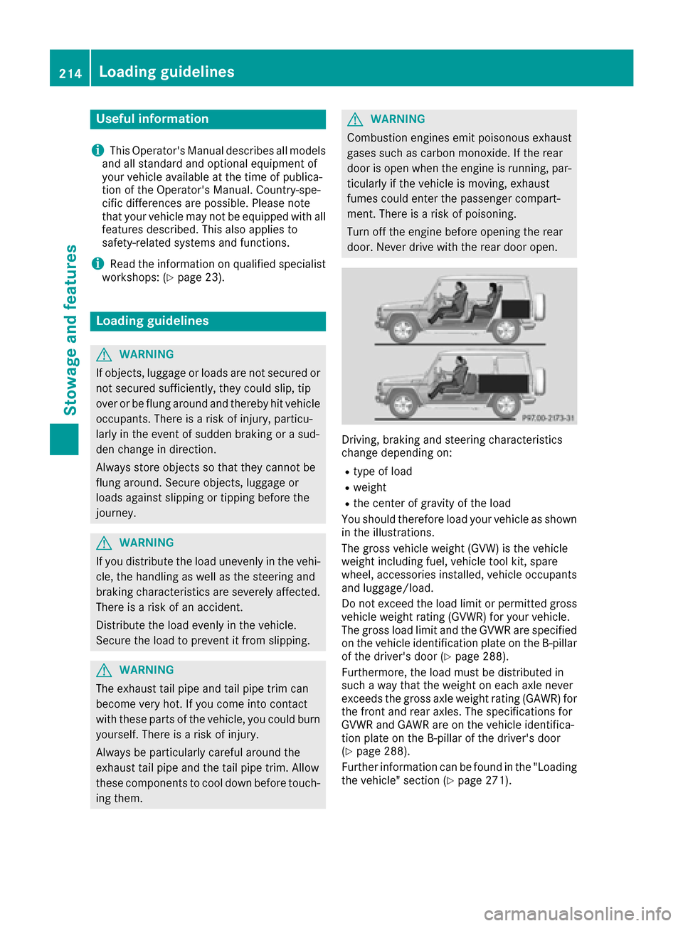
You should therefore load your vehicle as shown
in the illustrations.
The gross vehicle weight (GVW) is the vehicle
weight including fuel, vehicle tool kit, spare
wheel, accessories installed, vehicle occupants
and luggage/load.
Do not exceed the load limit or permitted gross
vehicle weight rating (GVWR) for your vehicle.
The gross load limit and the GVWR are specified
on the vehicle identification plate on the B-pillar
of the driver's door (
Ypage 288).
Furthermore, the load must be distributed in
such a way that the weight on each axle never
exceeds the gross axle weight rating (GAWR) for
the front and rear axles. The specifications for
GVWR and GAWR are on the vehicle identifica-
tion plate on the B-pillar of the driver's door
(
Ypage 288).
Further information can be found in the "Loading
the vehicle" section (
Ypage 271).
214Loading guidelines
Stowage and features
Page 229 of 302
If a connection can be made, theCall Con‐nectedmessage appears in the multifunction
display.
If a mobile phone network is available and there
is sufficient GPS reception, the mbrace system
transmits data to the Response Center, for
example:
Rcurrent location of the vehicle
Rvehicle identification number
Rvehicle model
Rvehicle color
iThe COMAND display shows that an mbrace
call is active. You can change to the naviga-
tion menu by pressing the NAVI button on
COMAND during the call. Voice output is not
available.
A voice connection is established between the
Mercedes-Benz Roadside Assistance Represen- tative and the vehicle occupants.
The Mercedes-Benz Roadside Assistance Rep-
resentative either sends a qualified Mercedes-
Benz technician or makes arrangements for
your vehicle to be transported to the nearest
authorized Mercedes-Benz Center. You may be
charged for services such as repair work and/or
towing. Further details are available in your
mbrace manual.
XDescribe the type of assistance needed.
iIf the indicator lamp in Roadside Assistance
button :is flashing continuously and no
voice connection with the Response center
has been established, then the mbrace sys-
tem has not been able to initiate a Roadside
Assistance call (e.g. the relevant mobile
phone network is not available). The Call
Failedmessage appears in the multifunction
display.
XTo end a call: press the~button on the
multifunction steering wheel.
or
XPress the corresponding COMAND button to
end a phone call.
iSign and drive services1: you are not
charged for services such as jump-starting,
providing a few gallons of fuel for a fuel tank
that has been run dry or changing a faulty tire
with the vehicle's own spare wheel.
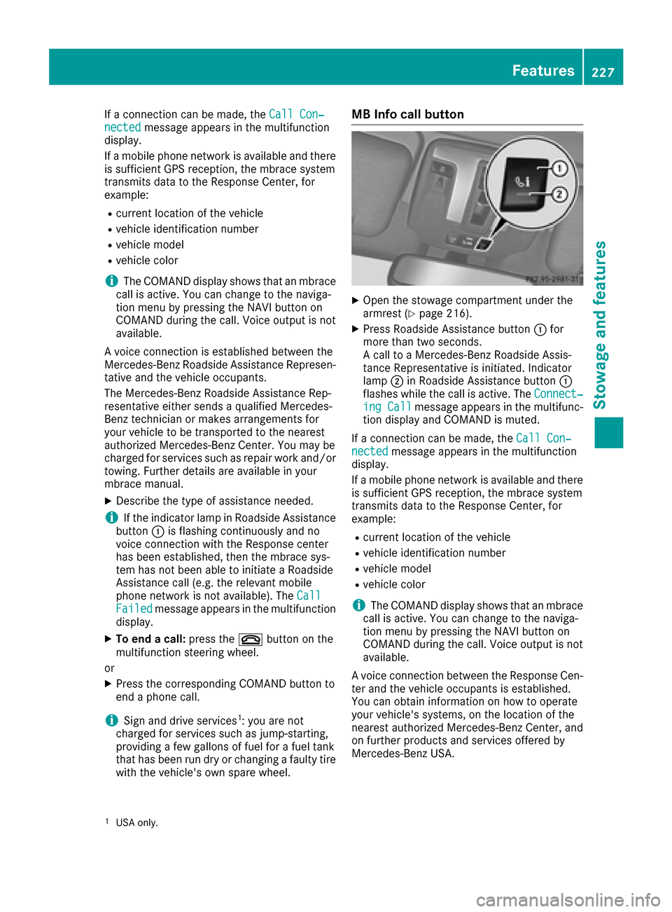
MB Info call button
XOpen the stowage compartment under the
armrest (Ypage 216).
XPress Roadside Assistance button :for
more than two seconds.
A call to a Mercedes-Benz Roadside Assis-
tance Representative is initiated. Indicator
lamp ;in Roadside Assistance button :
flashes while the call is active. The Connect‐
ing Callmessage appears in the multifunc-
tion display and COMAND is muted.
If a connection can be made, the Call Con‐
nectedmessage appears in the multifunction
display.
If a mobile phone network is available and there
is sufficient GPS reception, the mbrace system
transmits data to the Response Center, for
example:
Rcurrent location of the vehicle
Rvehicle identification number
Rvehicle model
Rvehicle color
iThe COMAND display shows that an mbrace
call is active. You can change to the naviga-
tion menu by pressing the NAVI button on
COMAND during the call. Voice output is not
available.
A voice connection between the Response Cen- ter and the vehicle occupants is established.
You can obtain information on how to operate
your vehicle's systems, on the location of the
nearest authorized Mercedes-Benz Center, and
on further products and services offered by
Mercedes-Benz USA.
1USA only.
Features227
Stowage and features
Z
Page 251 of 302
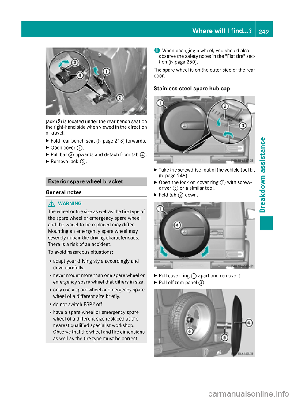
Jack;is located under the rear bench seat on
the right-hand side when viewed in the direction
of travel.
XFold rear bench seat (Ypage 218) forwards.
XOpen cover :.
XPull bar=upwards and detach from tab ?.
XRemove jack;.
Exterior spare wheel bracket
General notes
GWARNING
The wheel or tire size as well as the tire type of the spare wheel or emergency spare wheel
and the wheel to be replaced may differ.
Mounting an emergency spare wheel may
severely impair the driving characteristics.
There is a risk of an accident.
To avoid hazardous situations:
Radapt your driving style accordingly and
drive carefully.
Rnever mount more than one spare wheel or
emergency spare wheel that differs in size.
Ronly use a spare wheel or emergency spare
wheel of a different size briefly.
Rdo not switch ESP®off.
Rhave a spare wheel or emergency spare
wheel of a different size replaced at the
nearest qualified specialist workshop.
Observe that the wheel and tire dimensions
as well as the tire type must be correct.
iWhen changing a wheel, you should also
observe the safety notes in the "Flat tire" sec-
tion (
Ypage 250).
The spare wheel is on the outer side of the rear
door.
Stainless-steel spare hub cap
XTake the screwdriver out of the vehicle tool kit
(Ypage 248).
XOpen the lock on cover ring :with screw-
driver =or a similar tool.
XFold tab ;down.
XPull cover ring :apart and remove it.
XPull off trim panel ?.
Where will I find...?249
Breakdown assistance
Z
Page 252 of 302

iWhen re-installing trim panel?, make sure
that retainer Aengages in recess B.
Removing the spare wheel
The spare wheel is heavy. Take particular note of
this when removing the spare wheel.
XRemove wheel nuts :.
XRemove the spare wheel.
Mounting the wheel
After changing a wheel:
XRepair or replace the damaged wheel as soon
as possible and secure the spare wheel in
place again.
XSecure the damaged wheel on the spare
wheel bracket with wheel nuts :. When
doing so, make sure that the wheel cannot
come loose.
XWhen re-installing trim panel ?, make sure
that retainer Bengages in recess A
(
Ypage 249).
XMake sure that tab ;is below when re-
installing cover ring :(Ypage 249).
XFor safety reasons, regularly check to ensure
that the wheel is securely fastened.
Flat tire
Preparing the vehicle
XStop the vehicle on solid, non-slippery and
level ground, as far away as possible from
traffic.
XSwitch on the hazard warning lamps
(Ypage 89).
XApply the parking brake.
XBring the front wheels into the straight-ahead
position.
XMove the selector lever to position P.
XSwitch off the engine.
XRemove the SmartKey from the ignition lock.
The steering wheel lock stays active for as
long as the SmartKey is removed.
XAll occupants must get out of the vehicle.
Make sure that they are not endangered as
they do so.
XMake sure that no one is near the danger area
while a wheel is being changed. Anyone who
is not directly assisting in the wheel change
should, for example, stand behind the barrier.
XGet out of the vehicle. Pay attention to traffic
conditions when doing so.
XClose the driver's door.
Battery (vehicle)
Important safety notes
Special tools and expert knowledge are required
when working on the battery, e.g. removal and
installation. You should therefore have all work
involving the battery carried out at a qualified
specialist workshop.
GWARNING
Work carried out incorrectly on the battery
can lead, for example, to a short circuit and
thus damage the vehicle electronics. This can
lead to function restrictions applying to
safety-relevant systems, e.g the lighting sys-
tem, the ABS (anti-lock braking system) or the
ESP
®(Electronic Stability Program). The oper-
ating safety of your vehicle may be restricted.
You could lose control of the vehicle, for
example:
Rwhen braking
Rin the event of abrupt steering maneuvers
and/or when the vehicle's speed is not
adapted to the road conditions
There is a risk of an accident.
In the event of a short circuit or a similar inci-
dent, contact a qualified specialist workshop
immediately. Do not drive any further. You
250Battery (vehicle)
Breakdown assistance
Page 264 of 302
Useful information
i
This Operator's Manual describes all models
and all standard and optional equipment of
your vehicle available at the time of publica-
tion of the Operator's Manual. Country-spe-
cific differences are possible. Please note
that your vehicle may not be equipped with all
features described. This also applies to
safety-related systems and functions.
iRead the information on qualified specialist
workshops: (Ypage 23).
Important safety notes
GWARNING
If wheels and tires of the wrong size are used, the wheel brakes or suspension components
may be damaged. There is a risk of an acci-
dent.
Always replace wheels and tires with those
that fulfill the specifications of the original
part.
When replacing wheels, make sure to use the
correct:
Rdesignation
Rmodel
When replacing tires, make sure to use the
correct:
Rdesignation
Rmanufacturer
Rmodel
GWarning
A flat tire severely impairs the driving, steer-
ing and braking characteristics of the vehicle.
There is a risk of an accident.
do not drive with a flat tire. Immediately
replace the flat tire with your spare wheel, or
consult a qualified specialist workshop.
Contact an authorized Mercedes-Benz Center if
you require information on tested and recom-
mended wheels and tires for summer and winter
driving. Advice on purchasing and caring for
tires is also available there. Accessories that are not approved for your vehi-
cle by Mercedes-Benz or are not being used cor-
rectly can impair the operating safety.
Before purchasing and using non-approved
accessories, visit a qualified specialist work-
shop and ask about:
Rsuitability
Rlegal stipulations
Rfactory recommendations
Information on the dimensions and types of
wheels and tires for your vehicle can be found in
the "Wheel/tire combinations" section
(
Ypage 284).
Information on air pressure for the tires on your
vehicle can be found:
Ron the tire pressure label on the fuel filler flap
Rin the "Tire pressure" section
iFurther information on wheels and tires can
be obtained at any qualified specialist work-
shop.
Operation
Notes on driving
If the vehicle is heavily loaded, check the tire
pressures and correct them if necessary.
When parking your vehicle, make sure that the
tires do not get deformed by the curb or other
obstacles. If it is necessary to drive over curbs,
speed humps or similar elevations, try to do so
slowly and at an obtuse angle. Otherwise, the
tires, particularly the sidewalls, may be dam-
aged.
Regular checking of wheels and tires
GWARNING
Damaged tires can cause tire inflation pres-
sure loss. As a result, you could lose control of
your vehicle. There is a risk of accident.
Check the tires regularly for signs of damage
and replace any damaged tires immediately.
RRegularly check the wheels and tires of your
vehicle for damage at least once a month, as
well as after driving off-road or on rough
roads. Damage includes bulges and deforma-
tion on tires, cuts, punctures, cracks or
262Operation
Wheels and tires
Page 265 of 302
severe corrosion on wheels, for example.
Damaged wheels can cause a loss of tire pres-
sure.
RRegularly check the tire tread depth and the
condition of the tread across the whole width
of the tire (
Ypage 263). In order to inspect
the inner side of the tire surface, turn the
steering wheel to full lock.
RAll wheels must have a valve cap to protect
the valve against dirt and moisture. Do not
install anything onto the valve other than the
standard valve cap or a valve cap approved by Mercedes-Benz for your vehicle.
Do not install anything onto the valve, such as
tire pressure monitoring systems.
RYou should regularly check the pressure of all
your tires including the spare wheel, particu-
larly prior to long trips. Adjust the tire pres-
sure as necessary (
Ypage 270).
The service life of tires depends, among other
things, on the following factors:
RDriving style
RTire pressure
RDistance covered
Tire tread
GWARNING
Insufficient tire tread will reduce tire traction.
The tire is no longer able to dissipate water.
This means that on wet road surfaces, the risk
of hydroplaning increases, in particular where speed is not adapted to suit the driving con-
ditions. There is a risk of accident.
If the tire pressure is too high or too low, tires
may exhibit different levels of wear at differ-
ent locations on the tire tread. Thus, you
should regularly check the tread depth and
the condition of the tread across the entire
width of all tires.
Minimum tire tread depth for:
RSummer tires: âin (3 mm)
RM+S tires: ãin (4 mm)
For safety reasons, replace the tires before
the legally prescribed limit for the minimum
tire tread depth is reached.
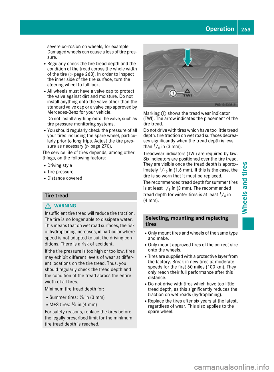
Marking :shows the tread wear indicator
(TWI). The arrow indicates the placement of the
tire tread.
Do not drive with tires which have too little tread
depth. tire traction on wet road surfaces decrea-
ses significantly when the tread depth is less
than
1/8in (3 mm).
Treadwear indicators (TWI) are required by law.
Six indicators are positioned over the tire tread.
They are visible once the tread depth is approx-
imately
1/16in (1.6 mm). If this is the case, the
tire is so worn that it must be replaced.
The recommended tread depth for summer tires
is at least
1/8in (3 mm). The recommended
tread depth for winter tires is at least1/6in
(4 mm).
Selecting, mounting and replacing
tires
ROnly mount tires and wheels of the same type
and make.
ROnly mount approved tires of the correct size
onto the wheels.
RTires are supplied with a protective layer from
the factory. Break in new tires at moderate
speeds for the first 60 miles (100 km). They
only reach their full performance after this
distance.
RDo not drive with tires which have too little
tread depth, as this significantly reduces the
traction on wet roads (hydroplaning).
RReplace the tires after six years at the latest,
regardless of wear. This also applies to the
spare wheel.
Operation263
Wheels and tires
Z