2016 MERCEDES-BENZ E-CLASS SALOON battery
[x] Cancel search: batteryPage 182 of 557

Plug-in
hybrid: obser vethe no tes on the high-
vo ltage battery in the separate Owner's Manual. St
andby mode St
andby mode function
St andby mode is characterised bythefo llowing:
R theve hicle can be par kedove r a long period
of time without losing po wer.
R theve hicle battery is preser ved.
R the maximum period out of use is displa yed
in the multimedia sy stem displa y.
R functions such as interior pr otection or tow-
aw ay protection are not available.
R the connection toonline services is inter rup‐
te d.
If th efo llowing conditions are fulfilled, standby
mode can be activated or deactivated using the
multimedia sy stem:
R the engine is switched off.
R the ignition is switched on. Exceeding
theve hicle's displa yed period out of
use may cause incon venience, i.e. it cannot be
guaranteed that thest ar ter battery will reliably
st art the engine.
The star ter battery must be charge d in thefo l‐
lowing situations:
R theve hicle's period out of use must be
ex tended.
R a messa geappears in the multimedia sy stem
display explaining that the battery charge is
insuf ficient forst andby mode.
% Standby mode is automatically deactivated
when the ignition is switched on.
Ac tivating or deactivating standby mode
Multimedia sy stem:
, Vehicle .
î Vehicle set-
tings .
Standby mode #
Activate Oor deacti vate ª the function.
When you activate the function, a prom pt
appears. #
Select Yes.
St andby mode is activated. Driving and driving saf
ety sy stems Driving sy
stems and your responsibility Yo
ur vehicle is equipped with driving sy stems
which assist you in driving, parking and manoeu‐
vring theve hicle. The driving sy stems are aids
and do not relie ve you of your responsibility. Pay
attention tothe tra ffic conditions at all times
and inter vene when necessa ry. Be aware of the
limitations rega rding the safe use of these sys‐
te ms. Fu
nction of thera dar senso rs Some driving and driving sa
fety sy stems use
ra dar sensors tomonitor the area in front of,
behind or next totheve hicle (depending on the
ve hicle's equipment).
Depending on theve hicle's equipment, thera dar
sensors are integrated behind the bumpers
and/or behind thera diator grille. Keep these
parts free of dirt, ice and slush . The sensors
must not be co vered, forex ample bybicycle
ra ck s, ove rhanging loads or radar-reflecting
st icke rs.Fo llowing an impact and in theeve nt of Driving and pa
rking 17 9
Page 200 of 557

As a
result, Dis tance Pilot DISTRONIC may
nei ther give warnings nor inter vene in su ch
situations. #
Alw ays carefully obser vethe traf fic con‐
ditions and be ready tobrake at all
times. &
WARNING Risk of accident due tolimi‐
te d de tectability of road users and traf fic
situations
Dis tance Pilot DISTRONIC cannot al ways
clear lyidentify other road users and complex
traf fic situations.
In these conditions, Dis tance Pil ot
DISTRONIC may:
R give an unnecessary warning and then
brake theve hicle
R neither give a warning nor inter vene
R accele rate or brake unexpectedly #
Continue driving with care and be ready
to brake, particular lyif Dis tance Pilot
DISTRONIC warnsyo u. &
WARNING Risk of accident due toinsuf‐
fi cient decele ration byDis tance Pilot
DISTRONIC
Dis tance Pilot DISTRONIC brakes your vehi‐
cle with up to50% of the maximum possible
braking po wer.If th is decele ration is not suf‐
fi cient, Dis tance Pilot DISTRONIC alerts you
with a visual and acoustic warning. #
Apply the brakes yourself in these situa‐
tions and try totake evasive action. &
WARNING Risk of accident due toDis‐
ta nce Pilot DISTRONIC still being activa‐
te d when you lea vethe driver's seat
If yo u lea vethe driver's seat while theve hicle
is being braked byDis tance Pilot DISTRONIC
only, it can rollaw ay inthefo llowing situa‐
tions:
R Ifth ere is a malfunction in the sy stem or
in the po wer supp ly. R
If Dis tance Pilot DISTRONIC is deacti va‐
te d with the cruise control le ver,e.g. by a
ve hicle occupant or from outside the
ve hicle.
R Ifth e electrics in the engine compart‐
ment, the battery or the fuses are tam‐
pered with.
R Ifth e battery is disconnected.
R Ifth eve hicle is accelerated, e.g. by a
ve hicle occupant. #
Alw ays deactivate Dis tance Pilot
DISTRONIC and secu retheve hicle to
pr eve nt it from rolling away before you
lea vethe driver's seat. &
WARNING Risk of accident due to
unknown stored speed
If yo u call up thestored speed and this is
lo we rth an your cur rent speed, theve hicle
decelerates.
If yo u do not kn owthestored speed, the
ve hicle could decelerate unexpectedl y. Driving and pa
rking 197
Page 206 of 557

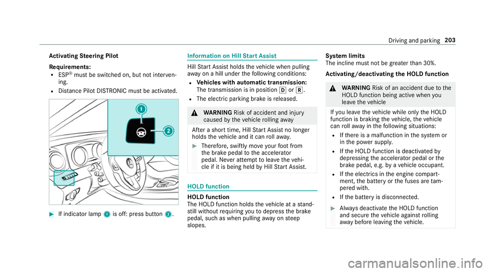
Ac
tivating Steering Pilot
Re quirements:
R ESP ®
must be switched on, but not inter ven‐
ing.
R Distance Pilot DISTRONIC mu stbe activated. #
If indicator lamp 1is off: press button 2. Information on Hill
Start Assist Hill
Start Assist holds theve hicle when pulling
aw ay on a hill under thefo llowing conditions:
R Vehicles with automatic transmission:
The transmission is in position hork.
R The electric parking brake is released. &
WARNING Risk of accident and inju ry
caused bytheve hicle rolling away
Af ter a short time, Hill Start Assist no lon ger
holds theve hicle and it can rollaw ay. #
Therefore, swiftly mo veyour foot from
th e brake pedal tothe accelerator
pedal. Ne ver attem pttolea vetheve hi‐
cle if it is being held byHill Start Assist. HOLD function
HOLD function
The HOLD function holds
theve hicle at a stand‐
st ill without requ iring youto depress the brake
pedal, such as when pulling away on steep
slopes. Sy
stem limits
The incline must not be greaterth an 30%.
Ac tivating/deactivating the HOLD function &
WARNING Risk of an accident due tothe
HOLD function being active when you
lea vetheve hicle
If yo u lea vetheve hicle while only the HOLD
function is braking theve hicle, theve hicle
can rollaw ay inthefo llowing situations:
R Ifth ere is a malfunction in the sy stem or
in the po wer supp ly.
R Ifth e HOLD function is deactivated by
depressing the accelera tor pedal or the
brake pedal, e.g. byave hicle occupant.
R Ifth e electrics in the engine compart‐
ment, the battery or the fuses are tam‐
pered with.
R Ifth e battery is disconnected. #
Alw ays deactivate the HOLD function
and secure theve hicle against rolling
aw ay before leaving theve hicle. Driving and parking
203
Page 243 of 557

The operation of
thefo llowing sy stems depends
on the trailer being connected cor rectly:
R ESP ®
R Parking Assist PARKTRONIC
R Parking Pilot
R Blind Spot Assist or Active Blind Spot Assi st
R Active Lane Keeping Assist
Coupling up a trailer
* NO
TEDama getothe battery due tofull
dischar ge Charging
the trailer battery using the po wer
supply of the trailer can damage the batter y. #
Do not use the po wer supp lyto charge
th e trailer batter y.#
Remo vethe pr otective co vering from the ball
head and store it in a safe place. #
Position the trailer on a le vel sur face behind
th eve hicle and couple it up totheve hicle. #
Open the soc ket co ver. #
Insert the plug connector with lug 1into
groo ve3 onthe soc ket. #
Turn bayonet coupling 2around clo ckwise
to thestop. #
Let the co ver engage. #
Secure the cable tothe trailer with cable ties
(if you are using an adap ter cable). #
Make sure that cable is alw ays slack for ease
of mo vement when cornering. #
Check the trailer lighting sy stem. Push the
combination switch up wards/down wards and
check whe ther the cor responding turn
signal light on the trailer is flashing.
A display message may appear in the multifunc‐
tion display even if the trailer has been connec‐
te d cor rectly:
R LEDs ha vebeen ins talled on the trailer light‐
ing sy stem
R the cur rent has fallen below the trailer light‐
ing sy stem's minimum cur rent (50 mA)
% Accessories can be connected tothe perma‐
nent po wer supp lyand the po wer supply that
is swit ched on via the ignition lock with max‐
imum po wer consum ptions of 180W.
Un coupling a trailer &
WARNING Risk of being crushed and
becoming trapped when uncoupling a
trailer
When uncoupling a trailer wi than engaged
ine rtia-activated brake, your hand may
become trapped between theve hicle and the
trailer dr awbar. 240
Driving and pa rking
Page 323 of 557

in
theeve nt of a breakdown or a similar situa‐
tion.
Messages in the multimedia sy stem displa y:
SOS READY : emergency call available
SOS NOT READY: the ignition is not on or there
is a malfunction with the emer gency call sy stem.
During an active emer gency call, Gappears
in the displa y.
Yo u can find more information on there gional
av ailability of the Mercedes-Benz emer gency call
sy stem at: http://www.mercedes-benz.com/
connect_ecall
% If an emer gency call is una vailable, a mes‐
sage tothis ef fect also appea rsinthe multi‐
function display of the instrument clus ter.
Au tomatic eme rgency call
Re quirements:
R The ignition is switched on.
R The star ter battery has been suf ficiently
ch arge d.
If re stra int sy stems such as airbags or seat belt
te nsioners ha vebeen activated af ter an acci‐ dent,
the Mercedes-Benz emer gency call sy stem
may automatically initiate an emer gency call.
The emergency call has been made:
R avo ice connection is made tothe Mercedes-
Benz emer gency call centre.
R a messa gewith accident data is transmitted
to the Mercedes-Benz emer gency call centre.
The Mercedes-Benz emergency call centre
can transmit theve hicle position data toone
of the public emer gency services call cen‐
tres.
R in cer tain situations additional data is trans‐
mit tedto the Mercedes-Benz emer gency call
centre.
This allo wsmeasu resfo rre scue, reco very or
to wing toa Mercedes-Benz service centre to
be initiated quickl y.
If yo ur vehicle is equipped with an SOS button in
th eove rhead control panel, it flashes until the
emer gency call has been compl eted.
It is not possible toimmediately end an auto‐
matic emer gency call. If
th e Mercedes-Benz emer gency call sy stem
cann otconnect tothe Mercedes-Benz emer‐
ge ncy call centre, the emer gency call is au tomat‐
ical lysent tothe public emer gency services call
centre.
If no connection can be made tothe public
emer gency services, a releva nt messa ge
appears in the displa y. #
Dial the emer gency call number 999 or 11 2
on your mobile phone.
If an eme rgency call has been initiated:
R remain in theve hicle, if thero ad and traf fic
conditions permit youto do so, until a voice
connection is es tablished with the emer‐
ge ncy call centre operator.
R onthe basis of the call, the operator decides
whe ther it is necessary todeploy rescue
te ams and/or the police tothe accident site.
R if no vehicle occupant answers, an ambu‐
lance is sent totheve hicle immediatel y.320
Multimedia sy stem
Page 325 of 557

%
ForRu ssia: various functions, e.g. receiving
traf fic information, cannot be per form ed for
up totwo hou rsafte r sending an emer gency
call.
St arting/ending ERA-GLONASS test mode
(Russia)
Re quirements:
R The star ter battery has suf ficient charge.
R The ignition is switched on.
R The vehicle has been stationary for at least
one minute. #
Tostart thete st mode: press and hold the
~ button on the multifunction steering
wheel for at least five seconds.
The test mode is star ted and automatically
ends af terth e language test has been per‐
fo rm ed. #
Toend thete st mode manuall y:switch off
th e ignition.
The test mode is ended. Te
lephone module with Blue tooth ®
(SAP pro‐
fi le) Fi
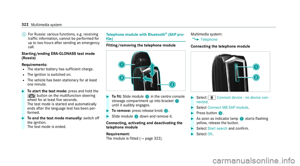
tting/ removing the telephone module #
Tofit: Slide module 2inthe cent reconsole
stow age compartment up into brac ket1
until it audibly engages. #
Toremo ve: press release knob 3. #
Slide module 2down and remo veit.
Connecting, acti vating and deactivating the
te lephone module
Re quirement:
The module is fitted (→ page 322). Multimedia sy
stem:
, Telephone
Connecting thete lephone module #
Select áConnect device - no device con-
nected. #
Select Connect MB SAP module. #
Press button 2. #
As soon as indicator lamp 1starts flashing
ye llo w, release the button. #
Select Start search and confirm. #
Select OK. 322
Multimedia sy stem
Page 367 of 557

Battery disconnection periods
The AS
SYST PLUS service inter val display
can only calculate the service due da tewhen
th e bat tery is connected. #
Notedown the service due date displa yed in
th e instrument display before disconnecting
th e battery (→ page 363). Engine compartment
Ac
tive bonn et(pedestrian pr otection) Operation of
the active bonnet (pedestrian
pr otection)
In cer tain accident situations, therisk of injury
to pedestrians can be reduced bythe actuation
of the active bonn et. The rear area of the engine
bonn etisraised byappr oximately 85 mm.
Fo rth e drive tothewo rkshop, reset the trig‐
ge red active bonn etyourself. If the active bonn et
has been triggered, pedestrian pr otection may
be limited.
A qu alified specialist workshop must re-ins tate
th e full functionality of the active bonn et. The active bonnet is not
available in all coun‐
tries.
Re setting the active bonnet &
WARNING Danger of bu rns from hot
component parts in the engine compart‐
ment
Cer tain component parts in the engine com‐
partment may be very hot, e.g. the engine,
th era diator and parts of theex haust sy stem. #
Let the engine cool down and only
to uch the component parts described
below: #
With your hand flat, push down active bonnet
1 inthe area around the hinges on bo th
sides (ar rows).
The engine bonnet must engage in position. #
Ifth e active bonn etcan be raised slight lyat
th ere ar in the area of the hinges, repeat the
st ep until it engages cor rectly in position. 364
Maintenance and care
Page 390 of 557

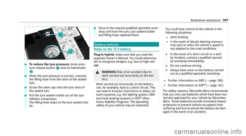
#
Toreduce the tyre pressure: press pres‐
su re re lease button 1next tomanome ter
2 . #
When the tyre pressure is cor rect, unscr ew
th efilling hose from theva lve of the sealed
tyre. #
Screw theva lve cap onto the tyre valve of
th e sealed tyre. #
Pull the tyre sealant bottle out of the tyre
inflation compressor.
The filling hose stay s on the tyre sealant bot‐
tle. #
Drive tothe nearest qualified specialist work‐
shop and ha vethe tyre, tyre sealant bottle
and filling hose replaced there. Batte
ry(vehicle) Note
s onthe12 V battery Plug-in
hybrid: make sure that youre ad the
separate Owner's Manual. You could otherwise
fa ilto recognise dangers, e.g. due tohigh volt‐
age. &
WARNING Risk of an accident due to
wo rkcar ried out incor rectly on the bat‐
te ry
Wo rkcar ried out incor rectly on the battery
can, forex ample, lead toa short circuit. This
can lead tofunction restrictions in saf ety-re l‐
eva nt sy stems, e.g. the lighting sy stem, ABS
(anti-lock braking sy stem) or ESP ®
(Elec‐
tronic Stability Prog ram). The operating
saf ety of your vehicle may be restricted. Yo
u could lose cont rol of theve hicle in the
fo llowing situations:
R when braking
R intheeve nt of ab rupt steering manoeu‐
vres and/or when theve hicle's speed is
not adap tedto thero ad conditions #
Intheeve nt of a sho rtcircuit or a simi‐
lar incident, contact a qualified special‐
ist workshop immediately. #
Do not continue driving. #
Alw ays ha vewo rkon the battery car ried
out at a qualified specialist workshop. R
Further information on ABS (→ page180)
R Further information on ESP ®
(→ page 181)
Fo r saf etyre asons, Mercedes-Benz recommends
th at you on lyuse bat teries which ha vebeen tes‐
te d and appr ovedfo ryo ur vehicle byMercedes-
Benz. These batteries pr ovide inc reased impact
pr otection toprev ent vehicle occupants from
suf fering acid bu rns should the battery be dam‐
aged in theeve nt of an accident. Breakdown assi
stance 387