2016 MERCEDES-BENZ E-CLASS ESTATE ESP
[x] Cancel search: ESPPage 136 of 565
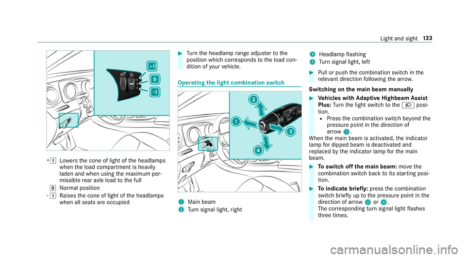
+1
Lowe rsthe cone of light of the headlamps
when the load compartment is heavily
laden and when using the maximum per‐
missible rear axle load tothe full
g Normal position
- 1
Raises the cone of light of the headlamps
when all seats are occupied #
Turn the headlamp range adjus terto the
position which cor responds tothe load con‐
dition of your vehicle. Operating
the light combination switch 1
Main beam
2 Turn signal light, right 3
Headlamp flashing
4 Turn signal light, left #
Pull or push the combination switch in the
re leva nt di rection following the ar row.
Switching on the main beam manually #
Vehicles with Adaptive Highbeam Assist
Plus: Turn the light switch totheL posi‐
tion. R Press the combination switch be yond the
pressure point in the direction of
ar ro w 1.
When the main beam is activated, the indicator
lamp for dipped beam is deactivated and
re placed bythe indicator lamp forth e main
beam. #
Toswitch off the main beam: movethe
combination switch ba cktoits starting posi‐
tion. #
Toindicate briefl y:press the combination
switch briefly up tothe pressure point in the
direction of ar row2or4.
The cor responding turn signal light flashes
th re e times. Light and sight
13 3
Page 139 of 565
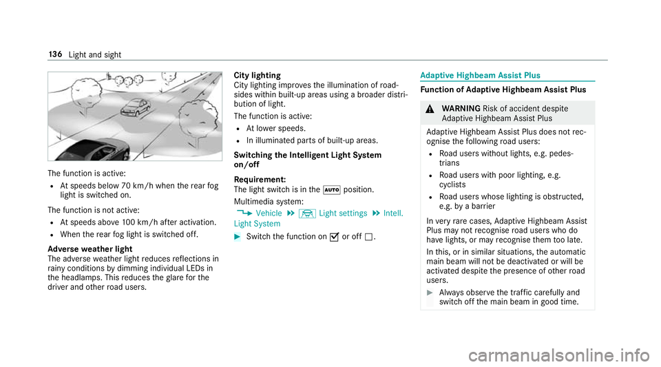
The function is active:
R Atspeeds below 70 km/h when there ar fog
light is switched on.
The function is not active:
R Atspeeds abo ve100 km/h af ter activation.
R When there ar fog light is switched off.
Ad versewe ather light
The adverse weather light reduces reflections in
ra iny conditions bydimming individual LEDs in
th e headlamps. This reduces theglare forthe
driver and other road users. City lighting
City lighting impr
ovesth e illumination of road‐
sides within built-up areas using a broader distri‐
bution of light.
The function is active:
R Atlowe r speeds.
R In illumina ted parts of built-up areas.
Switching the Intelligent Light Sy stem
on/off
Requ irement:
The light switch is in theà position.
Multimedia sy stem:
, Vehicle .
÷ Light settings .
Intell.
Light System #
Switch the function on Oor off ª. Ad
aptive Highbeam Assist Plus Fu
nction of Adaptive Highbeam Assist Plus &
WARNING Risk of accident despi te
Ad aptive Highbeam Assist Plus
Ad aptive Highbeam Assist Plus does not rec‐
ognise thefo llowing road users:
R Road users without lights, e.g. pedes‐
trians
R Road users with poor lighting, e.g.
cyclists
R Road users whose lighting is obstructed,
e.g. bya bar rier
In very rare cases, Adaptive Highbeam Assist
Plus may not recognise road users who do
ha ve lights, or may recognise them too late.
In this, or in similar situations, the automatic
main beam will not be deactivated or will be
activated despite the presence of other road
users. #
Alw ays obser vethe tra ffic carefully and
switch off the main beam in good time. 13 6
Light and sight
Page 149 of 565
skin,
eyes,respiratory organs or clo thing or
be swallo wed. #
Ifyo u come into contact with electro‐
ly te , obser vethefo llowing:
R Rinse the electrolyte from your skin
and seek medical attention immedi‐
atel y.
R If electrolyte comes into contact
with your eyes, rinse them thor‐
oughly with clean water and seek
medical attention immediately.
R Ifth e electrolyte is swallo wed,
immediately rinse your mouth out
th oroughly. Do not induce vomiting.
Seek medical attention immediately.
R Immedia tely ch ange out of clo thing
which has come into con tact wi th
electrolyte.
R If an allergic reaction occurs, seek
medical attention immediatel y.The outside mir
rors and inside rearview mir rors
on the driver's side automatically go into anti- dazzle mode if light from a headlamp hits
the
inside rearview mir ror.
Sy stem limitations
The mir rors do not go into anti-dazzle mode in
th efo llowing situations:
R the engine is switched off
R reve rsege ar is engaged
R interior lighting is swit ched on Pa
rking position of the passenger outside
mir ror The parking position makes parking easier.
The passenger outside mir ror tilts down wards
and sho wsthere ar wheel on the front passenger
side if:
R the parking position is stored
R the passenger mir ror is selected
R reve rsege ar is engaged
The passenger outside mir ror mo ves back toits
original position in thefo llowing situations: R
ifyo u shift the transmission toano ther trans‐
mission position
R when driving fasterthan 15 km/h
R ifyo u press the button forth e outside mir ror
on the driver's side Saving
the pa rking position of the passenger
outside mir ror Requ
irement:
Re versege ar must not be engaged when storing
using the memory button. 14 6
Light and sight
Page 171 of 565
ECO display
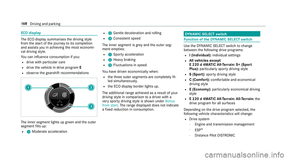
The ECO display summarises
the driving style
from thest art of the journey toits completion
and assists you in achieving the most economi‐
cal driving style.
Yo u can influence consum ption if you:
R drive with particular care
R drive theve hicle in drive program E
R obser vethege arshift recommendations The inner segment lights up green and
the outer
segment fills up:
R 1 Moderate acceleration R
2 Gentle decele ration and rolling
R 3 Consis tent speed
The inner segment is gr eyand the outer seg‐
ment em pties:
R 1 Sporty acceleration
R 2 Heavy braking
R 3 Fluctuations in speed
Yo u ha vedriven economically when:
R theth re e outer segments are comple tely fil‐
led simultaneousl y.
R the ECO display border lights up.
The additional range achi eved as a result of your
driving style in comparison toa driver with a
ve ry sporty driving style is shown under Bonus
from start. The range displ ayed does not indicate
a fixe dre duction in consum ption. DY
NA MIC SELECT switch Fu
nction of theDY NA MIC SELECT switch Use
theDY NA MIC SELECT switch tochange
between thefo llowing drive programs:
R I (Individual): individual settings
R Allvehicles except
E 220 d 4MATIC All‑Ter rain: S+ (Sport
Plus): particularly sporty driving style
R S (Sport): sporty driving style
R C (Comfort): comfortable and economical
driving style
R E (Economy): particularly economical driving
st yle
R E 220 d 4MATIC All‑Ter rain: All‑Ter rain: the
drive prog ram for all sur faces
Depending on the drive program selected, the
fo llowing vehicle characteristics will change:
R Drive sy stem
- Engine and transmission management
- ESP ®
- Distance Pilot DISTRONIC 16 8
Driving and pa rking
Page 177 of 565
#
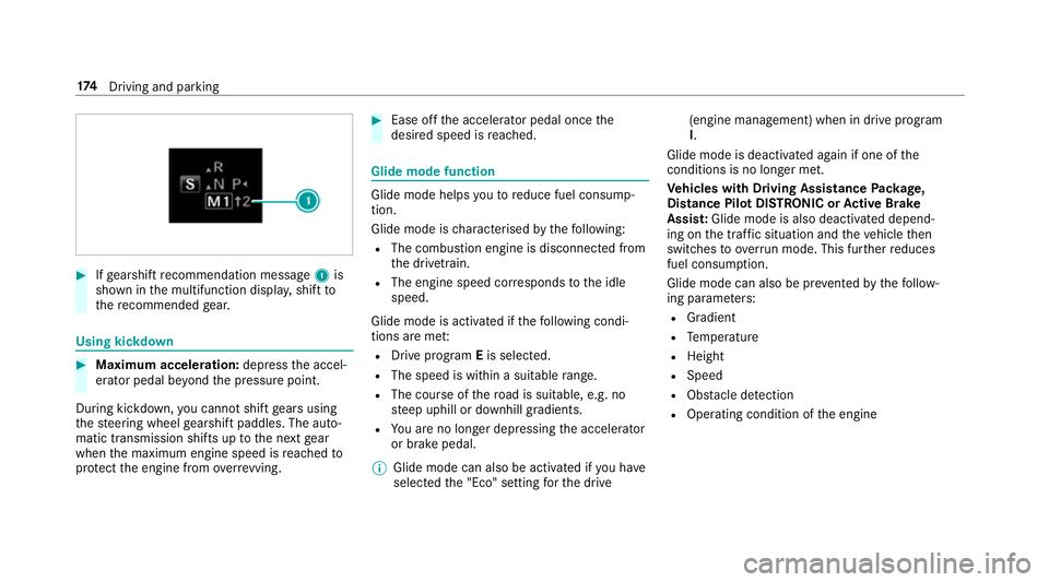
Ifge arshift recommendation message 1is
shown in the multifunction displa y,shift to
th ere commended gear. Using kickd
own #
Maximum acceleration: depressthe accel‐
erator pedal be yond the pressure point.
During kickdown, you cannot shift gears using
th esteering wheel gearshift paddles. The auto‐
matic transmission shifts up tothe next gear
when the maximum engine speed is reached to
pr otect the engine from overrev ving. #
Ease off the accelera tor pedal once the
desired speed is reached. Glide mode function
Glide mode helps
youto reduce fuel consump‐
tion.
Glide mode is characterised bythefo llowing:
R The combustion engine is disconnected from
th e driv etra in.
R The engine speed cor responds tothe idle
speed.
Glide mode is activated if thefo llowing condi‐
tions are me t:
R Drive program Eis selected.
R The speed is wi thin a suitable range.
R The cou rse of thero ad is suitable, e.g. no
st eep uphill or downhill gradients.
R You are no lon ger depressing the accelerator
or brake pedal.
% Glide mode can also be activated if you ha ve
selected the "Eco" setting forth e drive (engine management) when in drive program
I.
Glide mode is deactivated again if one of the
conditions is no longer met.
Ve hicles with Driving Assistance Package,
Dist ance Pil otDISTRONIC or Active Brake
Assi st:Glide mode is also deacti vated depend‐
ing on the traf fic situation and theve hicle then
switches toove rrun mode. This fur ther reduces
fuel consum ption.
Glide mode can also be pr evented bythefo llow‐
ing parame ters:
R Gradient
R Temp erature
R Height
R Speed
R Obs tacle de tection
R Ope rating condition of the engine 174
Driving and pa rking
Page 186 of 565
#
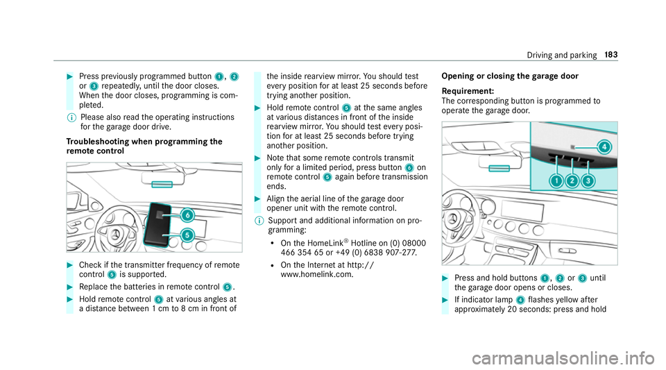
Press pr eviously prog rammed button 1,2
or 3 repeatedl y,until the door closes.
When the door closes, programming is com‐
ple ted.
% Please also read the operating instructions
fo rth ega rage door drive.
Tr oubleshooting when prog ramming the
re mo tecont rol #
Check if the transmit ter frequency of remo te
control 5is suppo rted. #
Replace the batteries in remo tecontrol 5. #
Hold remo tecontrol 5atvarious angles at
a dis tance between 1 cm to8 cm in front of th
e inside rearview mir ror.Yo u should test
eve ryposition for at least 25 seconds before
trying ano ther position. #
Hold remo tecontrol 5atthe same angles
at various dis tances in front of the inside
re arview mir ror.Yo u should test eve ryposi‐
tion for at least 25 seconds before trying
ano ther position. #
Notethat some remo tecontrols transmit
only for a limi ted period, press button 6on
re mo tecontrol 5again before transmission
ends. #
Align the aerial line of thega rage door
opener unit with there mo tecontrol.
% Support and additional information on pro‐
gramming:
R Onthe HomeLink ®
Hotline on (0) 08000
466 354 65 or +49 (0) 6838 907-2 77.
R Onthe Internet at http://
www.homelin k.com. Opening or closing the
garage door
Requ irement:
The cor responding button is programmed to
operate thega rage door. #
Press and hold buttons 1,2or3 until
th ega rage door opens or closes. #
If indicator lamp 4flashes yellow af ter
appr oximately 20 seconds: press and hold Driving and parking
18 3
Page 191 of 565
Driving and driving saf
ety sy stems Driving sy
stems and your responsibility Yo
ur vehicle is equipped with driving sy stems
which assist you in driving, parking and manoeu‐
vring theve hicle. The driving sy stems are aids
and do not relie ve you of your responsibility. Pay
attention tothe tra ffic conditions at all times
and inter vene when necessa ry. Be aware of the
limitations rega rding the safe use of these sys‐
te ms. Fu
nction of thera dar senso rs Some driving and driving sa
fety sy stems use
ra dar sensors tomonitor the area in front of,
behind or next totheve hicle (depending on the
ve hicle's equipment).
Depending on theve hicle's equipment, thera dar
sensors are integrated behind the bumpers
and/or behind thera diator grille. Keep these
parts free of dirt, ice and slush . The sensors
must not be co vered, forex ample bybicycle
ra ck s, ove rhanging loads or radar-reflecting
st icke rs.Fo llowing an impact and in theeve nt of associated dama
ge, which may not be visible, to
th e bumpers or radiator grille, ha vethe function
of thera dar sensors checked at a qualified spe‐
cialist workshop. The driver assis tance sy stem
may no longer workproperly. Overview of driving sy
stems and driving
saf ety sy stems In
this section, you will find information about
th efo llowing driving sy stems and driving saf ety
sy stems:
R 360° Camera (→ page 224)
R ABS (Anti-lock BrakingSystem)
(→ page 189)
R Distance Pilot DISTRONIC (→ page 202)
R Adaptive brake lights (→ page199)
R AIR BODY CONTROL (→ page214)
R Active Brake Assi st (→page 194)
R Active Lane Keeping Assist (→ page244)
R ATTENTION ASSIST (→ page 238)
R BAS (Bra keAssist System) (→ page189)
R DYNA MIC BODY CONTROL (→ page214) R
EBD ( Electronic Brakefo rc eDistribution)
(→ page 193)
R ESP ®
(Electronic Stability Program)
(→ page 189)
R DRIVE PIL OT (→page 209)
R HOLD function (→ page212)
R Steering Pilot (→ page 209)
R Limiter (→ page199)
R Parking Pilot (→ page 227)
R Parking Assist PARKTRONIC (→ page218)
R Reversing camera (→ page 221)
R Cruise control (→ page199)
R Blind Spot Assi stand Active Blind Spot Assi st
( → page 242)
R Traf fic Sign Assi st (→page 239) 18 8
Driving and pa rking
Page 192 of 565
Fu
nctions of ABS (anti-lock braking sy stem) ABS
regulates the brake pressure in critical driv‐
ing situations:
R During braking, the wheels are pr evented
from blocking, e.g. due tomaximum full-s top
braking or insuf ficient traction of the tyres.
R Vehicle steerability while braking is ensured.
R ABS is active from speeds of appr ox.
8 km/h.
If ABS inter venes when braking, you will feel a
pulsing in the brake pedal. The pulsating brake
pedal can be an indication of hazardous road
conditions and can ser veas a reminder totake
ex tra care while driving.
Sy stem limits
ABS may be impaired or may not function if a
malfunction has occur red and theye llow !
ABS warning lamp lights up continuously in the
instrument clus ter af terth e engine is star ted. Fu
nction of BAS (Brake Assist Sy stem) &
WARNING Risk of an accident caused by
a malfunction in BAS (Brake Assi stSys‐
te m)
If BA S is malfunctioning, the braking dis tance
may increase in an emergency braking situa‐
tion. #
Dep ress the brake pedal with full force
in emer gency braking situations. ABS
pr eve nts the wheels from locking. BA
S suppo rts yo ur eme rgency braking situation
with additional brake forc e.
If yo u depress the brake pedal quickl y,BA S is
acti vated:
R BAS au tomatical lyboosts the brake pres‐
sure.
R BAS can sho rten the braking dis tance.
R ABS pr events the wheels from locking.
The brakes will function as usual once you
re lease the brake pedal. BAS is deactivated. Fu
nctions of ESP ®
(Electronic Stability Pro‐
gr am) &
WARNING Risk of skidding if ESP ®
is
malfunctioning
If ESP ®
is malfunctioning, ESP ®
cannot car ry
out vehicle stabilisation. In addition, other
driving saf ety sy stems are switched off. #
Drive on carefull y. #
Have ESP ®
ch ecked at a qualified spe‐
cialist workshop. &
WARNING Risk of skidding if ESP ®
is
deactivated
If yo u deactivate ESP ®
, ESP ®
cannot car ry
out vehicle stabilisation. #
ESP ®
should on lybe deactivated in the
fo llowing situations. ESP
®
monitors and impr oves driving stability and
traction, particular ly inthefo llowing situations:
R When pulling away on wet or slippe ryroads. Driving and parking
18 9