2016 MERCEDES-BENZ CLA COUPE load capacity
[x] Cancel search: load capacityPage 274 of 345

Through-loading facility in the rear
compartment X
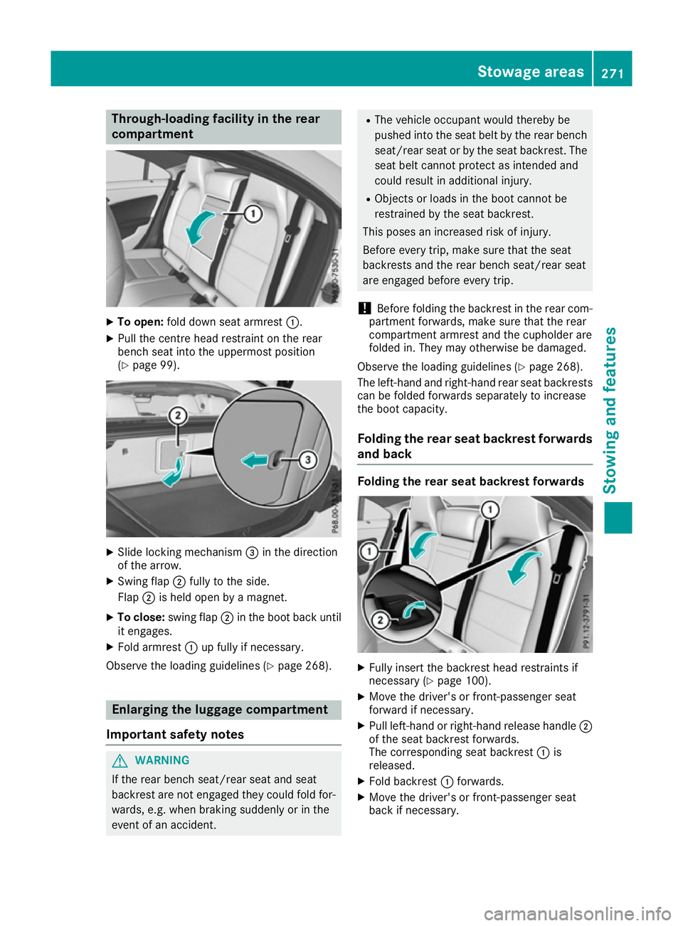
To open: fold down seat armrest :.
X Pull the centre head restraint on the rear
bench seat into the uppermost position
(Y page 99). X
Slide locking mechanism =in the direction
of the arrow.
X Swing flap ;fully to the side.
Flap ;is held open by a magnet.
X To close: swing flap ;in the boot back until
it engages.
X Fold armrest :up fully if necessary.
Observe the loading guidelines (Y page 268).Enlarging the luggage compartment
Important safety notes G
WARNING
If the rear bench seat/rear seat and seat
backrest are not engaged they could fold for- wards, e.g. when braking suddenly or in the
event of an accident. R
The vehicle occupant would thereby be
pushed into the seat belt by the rear bench
seat/rear seat or by the seat backrest. The
seat belt cannot protect as intended and
could result in additional injury.
R Objects or loads in the boot cannot be
restrained by the seat backrest.
This poses an increased risk of injury.
Before every trip, make sure that the seat
backrests and the rear bench seat/rear seat
are engaged before every trip.
! Before folding the backrest in the rear com-
partment forwards, make sure that the rear
compartment armrest and the cupholder are
folded in. They may otherwise be damaged.
Observe the loading guidelines (Y page 268).
The left-hand and right-hand rear seat backrests can be folded forwards separately to increase
the boot capacity.
Folding the rear seat backrest forwardsand back Folding the rear seat backrest forwards
X
Fully insert the backrest head restraints if
necessary (Y page 100).
X Move the driver's or front-passenger seat
forward if necessary.
X Pull left-hand or right-hand release handle ;
of the seat backrest forwards.
The corresponding seat backrest :is
released.
X Fold backrest :forwards.
X Move the driver's or front-passenger seat
back if necessary. Sto
wage areas
271Stowing and features Z
Page 277 of 345

size in the cup holder. Seal the container, in
particular when it contains hot liquid. G
WARNING
If objects in the passenger compartment are
stowed incorrectly, they can slide or be
thrown around and hit vehicle occupants. In
addition, cupholders, open stowage spaces
and mobile phone brackets cannot always
retain all objects they contain. There is a risk of injury, particularly in the event of sudden
braking or a sudden change in direction.
R Always stow objects so that they cannot be
thrown around in such situations.
R Always make sure that objects do not pro-
trude from stowage spaces, parcel nets or
stowage nets.
R Close the lockable stowage spaces before
starting a journey.
R Always stow and secure heavy, hard, poin-
ted, sharp-edged, fragile or bulky objects in
the boot.
! Only use the cup holders for containers of
the right size and which have lids. The drinks could otherwise spill.
Observe the loading guidelines (Y page 268).
The stowage compartments in the doors provide
space for bottles:
R front: capacity up to 1.0 l
R rear: capacity up to 0.5 l
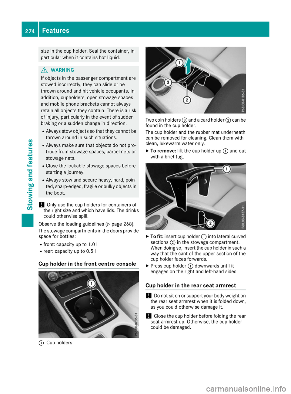
Cup holder in the front centre console :
Cup holders Two coin holders
=and a card holder ;can be
found in the cup holder.
The cup holder and the rubber mat underneath
can be removed for cleaning. Clean them with
clean, lukewarm water only.
X To remove: lift the cup holder up :and out
with a brief tug. X
To fit: insert cup holder :into lateral curved
sections ;in the stowage compartment.
When doing so, insert the cup holder in such a way that the cant of the upper section of the
cup holder faces forwards.
X Press cup holder :downwards until it
engages on the right and left-hand sides.
Cup holder in the rear seat armrest !
Do not sit on or support your body weight on
the rear seat armrest when it is folded down,
as you could otherwise damage it.
! Close the cup holder before folding the rear
seat armrest up. Otherwise, the cup holder
could be damaged. 274
FeaturesStowing and features
Page 297 of 345

Vehicle tool kit
General notes Vehicles with a TIREFIT kit: the TIREFIT kit is
located in the stowage well under the boot floor.
Vehicles with a tyre-change tool kit: the tyre-
change tool kit is in the stowage well under the
boot floor.
Vehicles with an emergency spare wheel, see
"Removing the emergency spare wheel"
(Y page 324).
Apart from some country-specific variants, vehi-
cles are not equipped with a tyre-change tool kit. Some tools for changing a tyre are specific to
the vehicle. For more information on which tyre-
changing tools are required and approved for
performing a tyre change on your vehicle, con-
sult a qualified specialist workshop.
Necessary tyre-changing tools may include, for
example:
R jack
R wheel chock
R Wheel wrench
R Centring pin
i The jack weighs approximately 3.4 kg.
The maximum load-bearing capacity of the
jack can be found on the adhesive label on the jack.
The jack is maintenance-free. If there is a
malfunction, please contact a qualified spe-
cialist workshop.
Vehicles with a TIREFIT kit :
Tyre inflation compressor
; Tyre sealant bottle
= Towing eye X
Open the boot lid.
X Swing the boot floor upwards (Y page 272).
X Use the TIREFIT kit (Y page 296)or remove it.
Towing eye =is located under tyre inflation
compressor :.
i The tyre inflation compressor weighs
approximately 0.8 kg.
The tyre inflation compressor is maintenance-
free. If there is a malfunction, please contact a qualified specialist workshop.
Vehicles with a tyre-change tool kit X
Open the boot lid.
X Swing the boot floor upwards (Y page 272).
X Remove the tyre-change tool kit.
The tyre-change tool kit contains:
R Jack
R Wheel wrench
R One pair of gloves
R Folding wheel chock Flat tyre
Preparing the vehicle
Your vehicle may be equipped with:
R MOExtended tyres (tyres with run-flat char-
acteristics) (Y page 295)
Vehicle preparation is not necessary on vehi- cles with MOExtended tyres.
R a TIREFIT kit (Y page 294)
R an emergency spare wheel (certain countries
only) (Y page 323)
Vehicles with MOExtended tyres are not equip-
ped with a TIREFIT kit at the factory. It is there-
fore recommended that you additionally equip
your vehicle with a TIREFIT kit if you fit tyres that do not feature run-flat characteristics, e.g. win-
ter tyres. A TIREFIT kit can be obtained from a
qualified specialist workshop.
Information on changing and fitting a wheel
(Y page 318).
X Stop the vehicle as far away as possible from
traffic on solid, non-slippery and level ground.
X Switch on the hazard warning lamps.
X Secure the vehicle against rolling away
(Y page 155). 294
Flat tyreBreakdown assistance
Page 298 of 345

X
If possible, bring the front wheels into the
straight-ahead position.
X Switch off the engine.
X Vehicles without KEYLESS-GO: remove the
key from the ignition lock.
X Vehicles with KEYLESS-GO start-function
or KEYLESS-GO: open the driver's door.
The vehicle electronics now have status 0.
This is the same as the key having been
removed.
X Vehicles with KEYLESS-GO start function
or KEYLESS-GO: remove the Start/Stop but-
ton from the ignition lock (Y page 133).
X Make sure that the passengers are not endan-
gered as they get out of the vehicle. Make
sure that no one is near the danger area while
a wheel is being changed. Anyone who is not directly assisting in the wheel change should, for example, stand behind the barrier.
X Get out of the vehicle. Pay attention to traffic
conditions when doing so.
X Close the driver's door.
X Place the warning triangle a suitable distance
away (Y page 293). Observe legal require-
ments. MOExtended tyres (tyres with run-flat
characteristics)
General notes With MOExtended tyres (tyres with run-flat char-
acteristics), you can continue to drive your vehi- cle even if there is a total loss of pressure in one
or more tyres. The affected tyre must not show
any clearly visible damage.
You can recognise MOExtended tyres by the
"MOExtended" marking that appears on the tyre sidewall. You will find this marking next to the
tyre size designation, the load-bearing capacity
and the speed index.
MOExtended tyres may be used only in conjunc- tion with an activated tyre pressure loss warning
system or tyre pressure monitor.
If a pressure loss warning message appears in the multifunction display:
R observe the instructions in the display mes-
sages (Y page 239)
R check the tyre for damage
R if driving on, observe the following notes The driving distance possible in run-flat mode is
approximately 80 km when the vehicle is parti-
ally laden and approximately 30 km when the
vehicle is fully laden.
In addition to the vehicle load, the driving dis-
tance possible in run-flat mode depends on the:
R vehicle speed
R road condition
R outside temperature
The driving distance possible in run-flat mode
may be reduced by extreme driving conditions/ manoeuvres, or it can be increased through a
moderate style of driving.
The driving distance possible in run-flat mode is
counted from the moment the tyre pressure loss warning appears on the multifunction display.
You must not exceed a maximum speed of
80 km/h.
When replacing one or all tyres, observe the fol-
lowing specifications for your vehicle's tyres:
R size
R type and
R the "MOExtended" marking
If a tyre has gone flat and cannot be replaced
with an MOExtended tyre, a standard tyre may
be used as a temporary measure. Make sure
that you use the proper size and type (summer
or winter tyre).
Vehicles with MOExtended tyres are not equip-
ped with a TIREFIT kit at the factory. It is there-
fore recommended that you additionally equip
your vehicle with a TIREFIT kit if you fit tyres that do not feature run-flat characteristics, e.g. win-
ter tyres. A TIREFIT kit can be obtained from a
qualified specialist workshop.
Important safety notes G
WARNING
When driving in emergency mode, the driving characteristics deteriorate, e.g. when corner-
ing, accelerating quickly and when braking.
There is a risk of accident.
Do not exceed the stated maximum speed.
Avoid abrupt steering and driving manoeu-
vres, and driving over obstacles (kerbs, pot-
holes, off-road). This applies in particular to a laden vehicle. Flat tyre
295Breakdown assistance
Z
Page 323 of 345

Raising the vehicle
G
WARNING
If you do not position the jack correctly at the appropriate jacking point of the vehicle, the
jack could tip over with the vehicle raised.
There is a risk of injury.
Only position the jack at the appropriate jack-
ing point of the vehicle. The base of the jack
must be positioned vertically, directly under
the jacking point of the vehicle.
Observe the following when raising the vehi- cle:
R only use the vehicle-specific jack that has
been tested and approved by Mercedes-Benz
to raise the vehicle. If the jack is used incor-
rectly, it could tip over while the vehicle is
raised.
R the jack is designed only to raise the vehicle
for a short time while a wheel is being
changed. It is not permissible to use it to per- form maintenance work under the vehicle.
R avoid changing the wheel on uphill and down-
hill slopes.
R before raising the vehicle, safeguard it from
rolling away by applying the parking brake and
positioning wheel chocks. Do not release theparking brake while the vehicle is raised.
R the jack must be placed on a firm, flat and
non-slip surface. On a loose surface, a large,
flat load-bearing underlay must be used. On a
slippery surface, a non-slip underlay must be
used, e.g. use a rubber mat on tiles.
R do not use wooden blocks or similar objects
as a jack underlay. Otherwise, the jack will not
be able to achieve its load-bearing capacity
due to the restricted height.
R make sure that the distance between the
underside of the tyres and the ground does
not exceed 3 cm.
R never place your hands or feet under the
raised vehicle.
R do not lie under the raised vehicle.
R do not start the engine when the vehicle is
raised.
R do not open or close a door or the boot lid
when the vehicle is raised.
R make sure that no persons are present in the
vehicle when raising the vehicle. Vehicles with steel wheels:
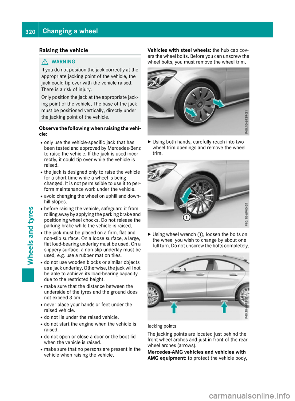
the hub cap cov-
ers the wheel bolts. Before you can unscrew the wheel bolts, you must remove the wheel trim. X
Using both hands, carefully reach into two
wheel trim openings and remove the wheel
trim. X
Using wheel wrench :, loosen the bolts on
the wheel you wish to change by about one
full turn. Do not unscrew the bolts completely. Jacking points
The jacking points are located just behind the
front wheel arches and just in front of the rear
wheel arches (arrows).
Mercedes-AMG vehicles and vehicles with
AMG equipment: to protect the vehicle body,320
Changing a wheelWheels and tyres