2016 MERCEDES-BENZ CLA COUPE flat tire
[x] Cancel search: flat tirePage 14 of 345
Entering an address
See also Digital Owner's Manual .. .259
Environmental protection
Returning an end-of-life vehicle ....... 24
ESP ®
(Electronic Stability Pro-
gram)
AMG menu (on-board computer) ... 214
Characteristics ................................. 70
Deactivating/activating (button
in Mercedes-AMG vehicles) ............. 71
Deactivating/activating (except
Mercedes‑AMG vehicles) ................. 70
Deactivating/activating (on-
board computer, except
Mercedes-AMG vehicles) .............. .209
Display message ............................ 217
Function/notes ................................ 69
General notes .................................. 69
Important safety guidelines ............. 70
Trailer stabilisatio n.......................... 72
Warning lamp ................................. 252
ETS/4ETS (Electronic Traction Sys-
tem) ...................................................... 70
Exhaust
see Exhaust pipe
Exhaust pipe
Cleaning ......................................... 290
Exterior lighting
Cleaning ......................................... 289
see Lights
Exterior mirrors
Adjusting ....................................... 103
Anti-dazzle mode (automatic) ........ 104
Folding in when locking (on-board computer) ...................................... 213
Folding in/out (automatically )....... 104
Folding in/out (electrically) ........... 104
Out of position (troubleshooting) ... 104
Parking position ............................. 105
Resetting ....................................... 104
Storing settings (memory func-
tion) ............................................... 106 F
Fault message see Display messages Favourites
Overview ........................................ 260
Filler cap
see Fuel filler flap
Fire extinguisher ............................... 293
First-aid kit ......................................... 293
Fitting a wheel
Fitting a wheel ............................... 321
Lowering the vehicle ...................... 322
Preparing the vehicle ..................... 319
Raising the vehicl e......................... 320
Removing a whee l.......................... 321
Securing the vehicle against roll-
ing away ........................................ 319
Flat tyre
Changing a wheel/fitting the
spare whee l................................... 318
MOExtended tyre s......................... 295
Preparing the vehicle ..................... 294
TIREFIT kit ...................................... 296
see Emergency spare wheel
Floormat ............................................. 278
Frequencies
Mobile phone ................................. 325
Two-way radio ................................ 325
Front-passenger front airbag deac-
tivation
Display message ............................ 226
Front-passenger front airbag deac-
tivation system
Operation ......................................... 47
Problems ......................................... 50
System self-test ............................... 49
Fuel
Additives ........................................ 329
Consumption statistics .................. 203
Displaying the current consump-
tion ................................................ 204
Displaying the range ...................... 204
Driving tip s.................................... 159
E10 ................................................ 328
Fuel gauge ....................................... 32
Grade (petrol) ................................ 328
Important safety notes .................. 328
Low outside temperatures ............. 330
Notes for CLA 250 ......................... 329
Notes for Mercedes ‑AMG vehi-
cles ................................................ 329 Index
11
Page 24 of 345
Trim pieces (cleaning instruc-
tions)
.................................................. 291
Trip computer (on-board com-
puter) .................................................. 203
Trip meter
Calling up ....................................... 203
Resetting (on-board computer) ...... 204
Turn signal lamp
Replacing bulbs (rear ).................... 113
Turn signals
Replacing bulbs (front) ................... 113
Switching on/of f........................... 109
Two-way radio
Frequencies ................................... 325
Installation ..................................... 325
Transmission output (maximum) .... 325
Type identification plate
see Vehicle identification plate
Tyre inflation compressor
see TIREFIT kit
Tyre pressure
Calling up (on-board computer) ..... 315
Display message ............................ 239
Not reached (TIREFIT) .................... 297
Reached (TIREFIT) .......................... 298
Recommended ............................... 313
Tyre pressure loss warning
General notes ................................ 314
Important safety notes .................. 315
Restarting ...................................... 315
Tyre pressure monitor
Checking the tyre pressure elec-
tronically ........................................ 316
Function/note s............................. 315
General notes ................................ 315
Important safety notes .................. 316
Radio type approval for the tyre
pressure monitor ........................... 317
Restarting ...................................... 317
Warning lamp ................................. 258
Warning message .......................... 317
Tyres
Changing a whee l.......................... 318
Checking ........................................ 310
Direction of rotation ...................... 319
Display message ............................ 239
General notes ................................ 323
Important safety notes .................. 310 Information on driving .................... 310
M+S tyres ...................................... 312
MOExtended tyre
s......................... 312
Replacing ....................................... 318
Service life ..................................... 311
Storing ........................................... 319
Summer tyres ................................ 312
Tyre size (data ).............................. 323
Tyre tread ...................................... 311
see Flat tyre U
Unlocking Emergency unlocking ....................... 85
From inside the vehicle (central
unlocking button) ............................. 84
Upshift indicator (on-board com-
puter, Mercedes-AMG vehicles) ....... 213
USB devices
Connecting to the Media Inter-
face ............................................... 267 V
Vanity mirror (in sun visor) .............. 275
Vehicle
Correct use ...................................... 28
Data acquisition ............................... 28
Display message ............................ 241
Electronics ..................................... 325
Equipment ....................................... 25
Implied warranty .............................. 28
Individual settings .......................... 210
Leaving parked up ......................... 159
Locking (in an emergency) ............... 85
Locking (key) ................................... 76
Lowering ........................................ 322
Pulling away ................................... 135
Raising ........................................... 320
Registration ..................................... 28
Securing from rolling away ............ 319
Transporting .................................. 307
Unlocking (in an emergency) ........... 85
Unlocking (key) ................................ 76
Vehicle data ................................... 333
Vehicle data
Boot load (maximum) ..................... 333
Roof load (maximum) ..................... 333 Index
21
Page 50 of 345

belt, a windowbag may be deployed in other
accident situations (Y page 51).Automatic front-passenger front air-
bag deactivation
Introduction In order to recognise a child restraint system on
the front-passenger seat, the automatic front-
passenger front airbag deactivation system cat- egorises the person in the front-passenger seat.Depending on that result, the front-passenger
front airbag is either enabled or disabled. If a
rearward-facing child restraint system is fitted
to the front-passenger seat, the PASSENGER
AIR BAG OFF indicator lamp must light up after
the system self-test and remain lit. The front-
passenger front airbag is disabled.
The system does not disable:
R the sidebag
R the windowbag
R the seat belt tensioner
Make sure that your vehicle is equipped with the automatic front-passenger front airbag deacti-
vation system (Y page 57). If this is not the
case, always install a child restraint system on a
suitable rear seat (Y page 59).
If it is absolutely necessary to install a child
restraint system on the front-passenger seat, be sure to observe the correct positioning of the
child restraint system. Never place objects
under or behind the child restraint system, e.g. a
cushion. Fully retract the seat cushion length.
The entire base of the child restraint system
must always rest on the seat cushion of the
front-passenger seat. The backrest of a forward-
facing child restraint system must, as far as
possible, rest flat against the backrest of the
front-passenger seat. The child restraint system must not touch the roof or be put under strain bythe head restraint. Adjust the angle of the seat
backrest and the head restraint position accord-
ingly. Only then is the correct function of the
automatic front-passenger front airbag deacti-
vation system guaranteed. Always observe the
information on suitable positioning of the child
restraint system (Y page 59) in addition to the
child restraint system manufacturer's installa-
tion instructions. Operation of automatic front-passenger
front airbag deactivation :
PASSENGER AIR BAG ON indicator lamp
; PASSENGER AIR BAG OFF indicator lamp
The indicator lamps inform you whether the
front-passenger front airbag is disabled or ena-
bled.
X Press the Start/Stop button once or twice, or
turn the key to position 1or 2in the ignition
lock.
The system carries out a self-diagnosis.
The PASSENGER AIR BAG OFF and PASSENGER
AIR BAG ON indicator lamps must light up simul- taneously for approximately six seconds.
The indicator lamps display the status of the
front-passenger front airbag:
R PASSENGER AIR BAG ON lights up for 60 sec-
onds, then both indicator lamps are off
(PASSENGER AIR BAG ON and OFF): the front-
passenger front airbag is able to deploy in the
event of an accident.
R PASSENGER AIR BAG OFF lights up: the front-
passenger front airbag is disabled. It will then
not be deployed in the event of an accident.
If the PASSENGER AIR BAG ON indicator lamp is
off, only the PASSENGER AIR BAG OFF indicator lamp shows the status of the front-passenger
front airbag. The PASSENGER AIR BAG OFF indi-
cator lamp may be lit continuously or be off.
If the status of the front-passenger front airbag
changes while the vehicle is in motion, an airbag display message appears on the instrument
cluster (Y page 226). When the front-passenger
seat is occupied, always pay attention to the
PASSENGER AIR BAG OFF indicator lamp. Be
aware of the status of the front-passenger front
airbag both before and during the journey. Occupant safety
47Safety Z
Page 62 of 345
Forward-facing child restraint system
If it is absolutely necessary to fit a forward-
facing child restraint system to the front-
passenger seat, always move the front-
passenger seat as far back as possible. Fully
retract the seat cushion length. The entire base of the child restraint system must always rest on
the seat cushion of the front-passenger seat.
The backrest of the child restraint system must, as far as possible, lie flat against the backrest of
the front-passenger seat. The child restraint sys- tem must not touch the roof or be put under
strain by the head restraint. Adjust the angle of
the seat backrest and the head restraint posi-
tion accordingly. Always make sure that the
shoulder belt strap is correctly routed from the
vehicle belt outlet to the shoulder belt guide on the child restraint system. The shoulder belt
strap must be routed forwards and downwards
from the vehicle belt outlet. If necessary, adjust
the vehicle belt outlet and the front-passenger
seat accordingly.
Always observe the information on suitable
positioning of the child restraint system
(Y page 59) in addition to the child restraint
system manufacturer's installation and operat-
ing instructions. Suitable positioning of the child
restraint system
Introduction Only child restraint systems approved in accord-
ance with ECE standards ECE R44 or ECE R129 (i-Size child restraint systems) are permitted for
use in the vehicle.
For certain child restraint systems in weight cat- egories II or III, this can mean that the area of
use is restricted. The maximum size setting of
the child restraint system may not be possible
due to possible contact with the roof.
"Universal" category child restraint systems can
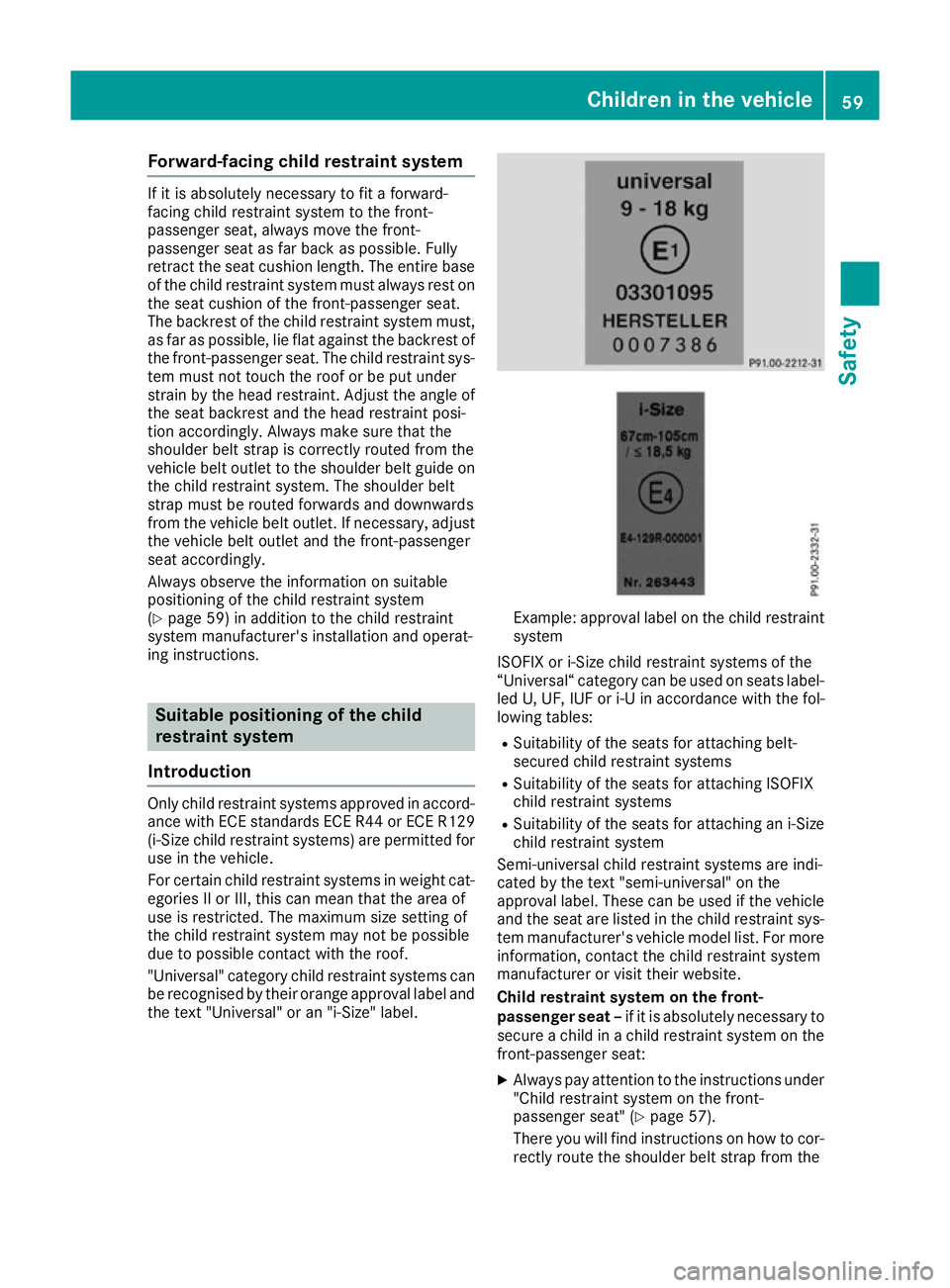
be recognised by their orange approval label and the text "Universal" or an "i-Size" label. Example: approval label on the child restraint
system
ISOFIX or i-Size child restraint systems of the
“Universal“ category can be used on seats label- led U, UF, IUF or i-U in accordance with the fol-
lowing tables:
R Suitability of the seats for attaching belt-
secured child restraint systems
R Suitability of the seats for attaching ISOFIX
child restraint systems
R Suitability of the seats for attaching an i-Size
child restraint system
Semi-universal child restraint systems are indi-
cated by the text "semi-universal" on the
approval label. These can be used if the vehicle and the seat are listed in the child restraint sys-
tem manufacturer's vehicle model list. For more
information, contact the child restraint system
manufacturer or visit their website.
Child restraint system on the front-
passenger seat – if it is absolutely necessary to
secure a child in a child restraint system on the front-passenger seat:
X Always pay attention to the instructions under
"Child restraint system on the front-
passenger seat" (Y page 57).
There you will find instructions on how to cor- rectly route the shoulder belt strap from the Children in the vehicle
59Safety Z
Page 63 of 345
vehicle belt outlet to the shoulder belt guide
on the child restraint system (Y page 59).
X Move the front-passenger seat as far back as
possible and fully retract the seat cushion
length.
If you secure a child in a forward-facing child
restraint system on the front-passenger seat,
you must also move the front-passenger seat to the highest position.
X Move the backrest to an almost vertical posi-
tion.
The entire base of the child restraint system
must always rest on the seat cushion of the front-passenger seat. The backrest of the
forward-facing child restraint system must, as far as possible, be resting on the backrest of
the front-passenger seat. The child restraint
system must not touch the roof or be put
under strain by the head restraint. Adjust the angle of the seat backrest and the head
restraint position accordingly. Also observe
the child restraint system manufacturer's
installation instructions.
X If possible, move the seat cushion angle to the
highest, most vertical position (Y page 98).
Suitability of the seats for attaching a belt-secured child restraint system If you use a baby car seat of category 0 or 0+ or a rearward-facing child restraint system of category
I on a rear seat, you must adjust the driver's or front-passenger seat so that the seat does not touch the child restraint system.
If you use a category I, forward-facing child restraint system, you should remove the head restraintfrom the respective seat, if possible (Y page 100). The backrest of the child restraint system must,
as far as possible, lie flat against the backrest of the seat.
Make sure that the child's feet do not touch the front seat. If necessary, move the front seat forward
slightly.
For certain child restraint systems in weight categories II or III, this can mean that the area of use is restricted. The maximum size setting of the child restraint system may not be possible due to
possible contact with the roof.
Always observe the notes in the "Child restraint system" section (Y page 54) and the child restraint
system manufacturer's installation instructions.
When you remove the child restraint system, you must replace the head restraints again immedi-
ately (Y page 99). All vehicle occupants must adjust their head restraints correctly before begin-
ning the journey.
Legend for the table:
XS eat that is unsuitable for children in this weight category.
US uitable for child restraint systems in the "Universal" category that are approved for use in this
weight category.
UF Suitable for forward-facing child restraint systems that belong to the "Universal" category and are approved for use in this weight category.
LS uitable for child restraint systems as recommended; see the "Recommended child restraint
systems" table (Y page 63). Suitable for semi-universal child restraint systems if the vehicle
and the seat are listed in the child restraint system manufacturer's vehicle model list. 60
Children in the vehicleSafety
Page 297 of 345

Vehicle tool kit
General notes Vehicles with a TIREFIT kit: the TIREFIT kit is
located in the stowage well under the boot floor.
Vehicles with a tyre-change tool kit: the tyre-
change tool kit is in the stowage well under the
boot floor.
Vehicles with an emergency spare wheel, see
"Removing the emergency spare wheel"
(Y page 324).
Apart from some country-specific variants, vehi-
cles are not equipped with a tyre-change tool kit. Some tools for changing a tyre are specific to
the vehicle. For more information on which tyre-
changing tools are required and approved for
performing a tyre change on your vehicle, con-
sult a qualified specialist workshop.
Necessary tyre-changing tools may include, for
example:
R jack
R wheel chock
R Wheel wrench
R Centring pin
i The jack weighs approximately 3.4 kg.
The maximum load-bearing capacity of the
jack can be found on the adhesive label on the jack.
The jack is maintenance-free. If there is a
malfunction, please contact a qualified spe-
cialist workshop.
Vehicles with a TIREFIT kit :
Tyre inflation compressor
; Tyre sealant bottle
= Towing eye X
Open the boot lid.
X Swing the boot floor upwards (Y page 272).
X Use the TIREFIT kit (Y page 296)or remove it.
Towing eye =is located under tyre inflation
compressor :.
i The tyre inflation compressor weighs
approximately 0.8 kg.
The tyre inflation compressor is maintenance-
free. If there is a malfunction, please contact a qualified specialist workshop.
Vehicles with a tyre-change tool kit X
Open the boot lid.
X Swing the boot floor upwards (Y page 272).
X Remove the tyre-change tool kit.
The tyre-change tool kit contains:
R Jack
R Wheel wrench
R One pair of gloves
R Folding wheel chock Flat tyre
Preparing the vehicle
Your vehicle may be equipped with:
R MOExtended tyres (tyres with run-flat char-
acteristics) (Y page 295)
Vehicle preparation is not necessary on vehi- cles with MOExtended tyres.
R a TIREFIT kit (Y page 294)
R an emergency spare wheel (certain countries
only) (Y page 323)
Vehicles with MOExtended tyres are not equip-
ped with a TIREFIT kit at the factory. It is there-
fore recommended that you additionally equip
your vehicle with a TIREFIT kit if you fit tyres that do not feature run-flat characteristics, e.g. win-
ter tyres. A TIREFIT kit can be obtained from a
qualified specialist workshop.
Information on changing and fitting a wheel
(Y page 318).
X Stop the vehicle as far away as possible from
traffic on solid, non-slippery and level ground.
X Switch on the hazard warning lamps.
X Secure the vehicle against rolling away
(Y page 155). 294
Flat tyreBreakdown assistance
Page 298 of 345
X
If possible, bring the front wheels into the
straight-ahead position.
X Switch off the engine.
X Vehicles without KEYLESS-GO: remove the
key from the ignition lock.
X Vehicles with KEYLESS-GO start-function
or KEYLESS-GO: open the driver's door.
The vehicle electronics now have status 0.
This is the same as the key having been
removed.
X Vehicles with KEYLESS-GO start function
or KEYLESS-GO: remove the Start/Stop but-
ton from the ignition lock (Y page 133).
X Make sure that the passengers are not endan-
gered as they get out of the vehicle. Make
sure that no one is near the danger area while
a wheel is being changed. Anyone who is not directly assisting in the wheel change should, for example, stand behind the barrier.
X Get out of the vehicle. Pay attention to traffic
conditions when doing so.
X Close the driver's door.
X Place the warning triangle a suitable distance
away (Y page 293). Observe legal require-
ments. MOExtended tyres (tyres with run-flat
characteristics)
General notes With MOExtended tyres (tyres with run-flat char-
acteristics), you can continue to drive your vehi- cle even if there is a total loss of pressure in one
or more tyres. The affected tyre must not show
any clearly visible damage.
You can recognise MOExtended tyres by the
"MOExtended" marking that appears on the tyre sidewall. You will find this marking next to the
tyre size designation, the load-bearing capacity
and the speed index.
MOExtended tyres may be used only in conjunc- tion with an activated tyre pressure loss warning
system or tyre pressure monitor.
If a pressure loss warning message appears in the multifunction display:
R observe the instructions in the display mes-
sages (Y page 239)
R check the tyre for damage
R if driving on, observe the following notes The driving distance possible in run-flat mode is
approximately 80 km when the vehicle is parti-
ally laden and approximately 30 km when the
vehicle is fully laden.
In addition to the vehicle load, the driving dis-
tance possible in run-flat mode depends on the:
R vehicle speed
R road condition
R outside temperature
The driving distance possible in run-flat mode
may be reduced by extreme driving conditions/ manoeuvres, or it can be increased through a
moderate style of driving.
The driving distance possible in run-flat mode is
counted from the moment the tyre pressure loss warning appears on the multifunction display.
You must not exceed a maximum speed of
80 km/h.
When replacing one or all tyres, observe the fol-
lowing specifications for your vehicle's tyres:
R size
R type and
R the "MOExtended" marking
If a tyre has gone flat and cannot be replaced
with an MOExtended tyre, a standard tyre may
be used as a temporary measure. Make sure
that you use the proper size and type (summer
or winter tyre).
Vehicles with MOExtended tyres are not equip-
ped with a TIREFIT kit at the factory. It is there-
fore recommended that you additionally equip
your vehicle with a TIREFIT kit if you fit tyres that do not feature run-flat characteristics, e.g. win-
ter tyres. A TIREFIT kit can be obtained from a
qualified specialist workshop.
Important safety notes G
WARNING
When driving in emergency mode, the driving characteristics deteriorate, e.g. when corner-
ing, accelerating quickly and when braking.
There is a risk of accident.
Do not exceed the stated maximum speed.
Avoid abrupt steering and driving manoeu-
vres, and driving over obstacles (kerbs, pot-
holes, off-road). This applies in particular to a laden vehicle. Flat tyre
295Breakdown assistance
Z
Page 299 of 345
Stop driving in emergency mode if:
R you hear banging noises.
R the vehicle starts to shake.
R you see smoke and smell rubber.
R ESP ®
is intervening constantly.
R there are tears in the sidewalls of the tyre.
After driving in emergency mode, have the
wheel rims checked at a qualified specialist
workshop with regard to their further use. The faulty tyre must be replaced. TIREFIT kit
Important safety notes TIREFIT is a tyre sealant.
You can use TIREFIT to seal punctures of up to
4 mm, particularly those in the tyre tread. You
can use TIREFIT at outside temperatures down
to Ò20 †. G
WARNING
In the following situations, the tyre sealant is
unable to provide sufficient breakdown assis- tance, as it is unable to seal the tyre properly:
R there are cuts or punctures in the tyre
larger than those mentioned above.
R the wheel rim is damaged.
R you have driven at very low tyre pressures
or on a flat tyre.
There is a risk of an accident.
Do not drive any further. Contact a qualified
specialist workshop. G
WARNING
The tyre sealant is harmful and causes irrita-
tion. It must not come into contact with your
skin, eyes or clothing or be swallowed. Do not inhale TIREFIT fumes. Keep tyre sealant away
from children. There is a risk of injury. If you come into contact with the tyre sealant,
observe the following:
R Rinse off the tyre sealant from your skin
immediately with water.
R If the tyre sealant comes into contact with
your eyes, immediately rinse them thor-
oughly with clean water.
R If tyre sealant is swallowed, immediately
rinse your mouth out thoroughly and drink
plenty of water. Do not induce vomiting,
and seek medical attention immediately.
R Immediately change out of clothing which
has come into contact with tyre sealant.
R If an allergic reaction occurs, seek medical
attention immediately.
! After use, excess tyre sealant may run out of
the filler hose. This could cause stains.
Therefore, place the filler hose in the plastic
bag which contained the TIREFIT kit. H
Environmental note
Have the used tyre sealant bottle disposed of
professionally, e.g. at a qualified specialist
workshop.
! Do not operate the tyre inflation compres-
sor for longer than ten minutes at a time with-
out a break. It may otherwise overheat.
The tyre inflation compressor can be oper-
ated again once it has cooled down.
Comply with the manufacturer's safety instruc-
tions on the sticker on the tyre inflation com-
pressor.
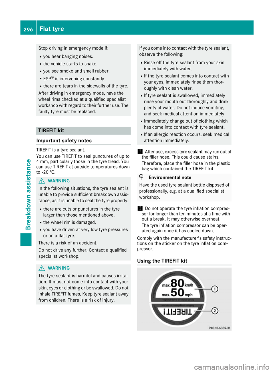
Using the TIREFIT kit 296
Flat tyreBreakdown assistance