2016 MERCEDES-BENZ CLA COUPE key
[x] Cancel search: keyPage 218 of 345

X
Press the %button on the steering wheel.
X Confirm Yes
Yes with a.
The RACETIMER interrupts timing if you stop the
vehicle and turn the key to position 1in the igni-
tion lock. If you turn the key to position 3and
then press ato confirm Start
Start, timing is
continued.
Resetting the current lap
X Stop the RACETIMER.
X Press the =or; button to select
Reset Lap
Reset Lap.
X Press ato reset the lap time to "0".
Deleting all laps If you switch off the engine, the RACETIMER is
reset to "0" after 30 seconds. All laps are
deleted.
You cannot delete individual stored laps. If you
have stopped 16 laps, the current lap does not
have to be reset.
X Reset the current lap.
X Press ato confirm Reset Reset.
Reset Race Timer?
Reset Race Timer? appears in the multi-
function display.
X Press the :button to select Yes
Yes and press
the a button to confirm.
All laps are deleted.
Overall evaluation :
RACETIMER overall evaluation
; Total time driven =
Average speed
? Distance covered
A Maximum speed
This function is shown if you have stored at least one lap and stopped the RACETIMER.
X Press =or; on the steering wheel to
select the AMG AMGmenu.
X Press the 9button repeatedly until the
overall evaluation appears.
Lap evaluation :
Lap
; Lap time
= Average lap speed
? Lap length
A Top speed during lap
This function is only available if you have stored
at least two laps and have stopped the RACE-
TIMER.
X Press the =or; button on the steering
wheel to select the AMG
AMG menu.
X Press the 9button repeatedly until a lap
evaluation appears.
Each lap is shown in a separate submenu. The fastest lap is indicated by flashing symbol :.
X Press the 9or: button to select a dif-
ferent lap evaluation. Menus and submenus
215On-board computer and displays Z
Page 222 of 345
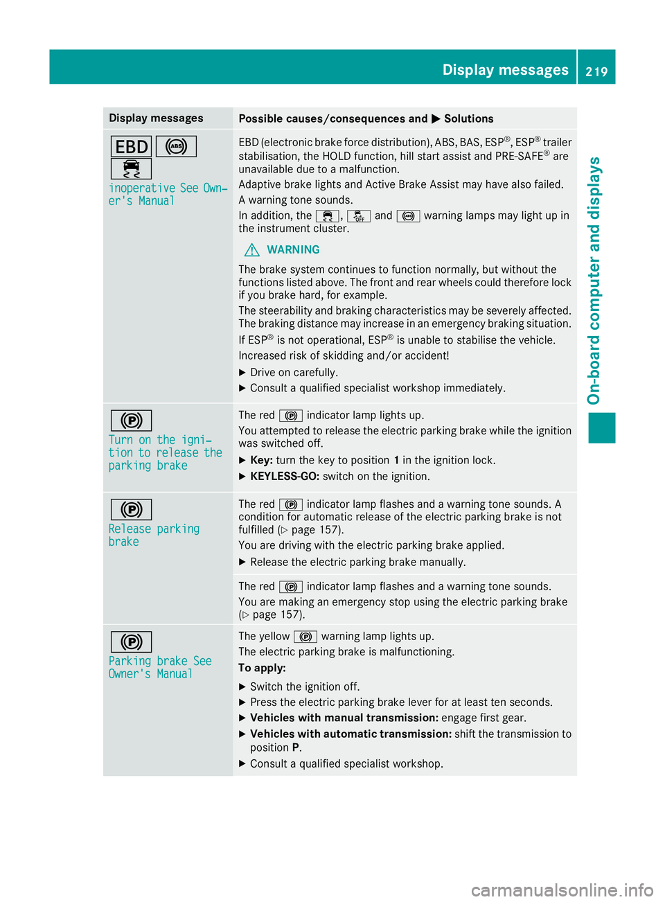
Display messages
Possible causes/consequences and
M
MSolutions T!
÷
inoperative inoperative See
SeeOwn‐
Own‐
er's Manual
er's Manual EBD (electronic brake force distribution), ABS, BAS, ESP
®
, ESP ®
trailer
stabilisation, the HOLD function, hill start assist and PRE-SAFE ®
are
unavailable due to a malfunction.
Adaptive brake lights and Active Brake Assist may have also failed.
A warning tone sounds.
In addition, the ÷,åand! warning lamps may light up in
the instrument cluster.
G WARNING
The brake system continues to function normally, but without the
functions listed above. The front and rear wheels could therefore lock
if you brake hard, for example.
The steerability and braking characteristics may be severely affected. The braking distance may increase in an emergency braking situation.
If ESP ®
is not operational, ESP ®
is unable to stabilise the vehicle.
Increased risk of skidding and/or accident!
X Drive on carefully.
X Consult a qualified specialist workshop immediately. !
Turn on the igni‐ Turn on the igni‐
tion tion
to
torelease
release the
the
parking brake
parking brake The red
!indicator lamp lights up.
You attempted to release the electric parking brake while the ignition
was switched off.
X Key: turn the key to position 1in the ignition lock.
X KEYLESS-GO: switch on the ignition. !
Release parking Release parking
brake brake The red
!indicator lamp flashes and a warning tone sounds. A
condition for automatic release of the electric parking brake is not
fulfilled (Y page 157).
You are driving with the electric parking brake applied.
X Release the electric parking brake manually. The red
!indicator lamp flashes and a warning tone sounds.
You are making an emergency stop using the electric parking brake
(Y page 157). !
Parking brake See Parking brake See
Owner's Manual Owner's Manual The yellow
!warning lamp lights up.
The electric parking brake is malfunctioning.
To apply:
X Switch the ignition off.
X Press the electric parking brake lever for at least ten seconds.
X Vehicles with manual transmission: engage first gear.
X Vehicles with automatic transmission: shift the transmission to
position P.
X Consult a qualified specialist workshop. Display
messages
219On-board computer and displays Z
Page 249 of 345
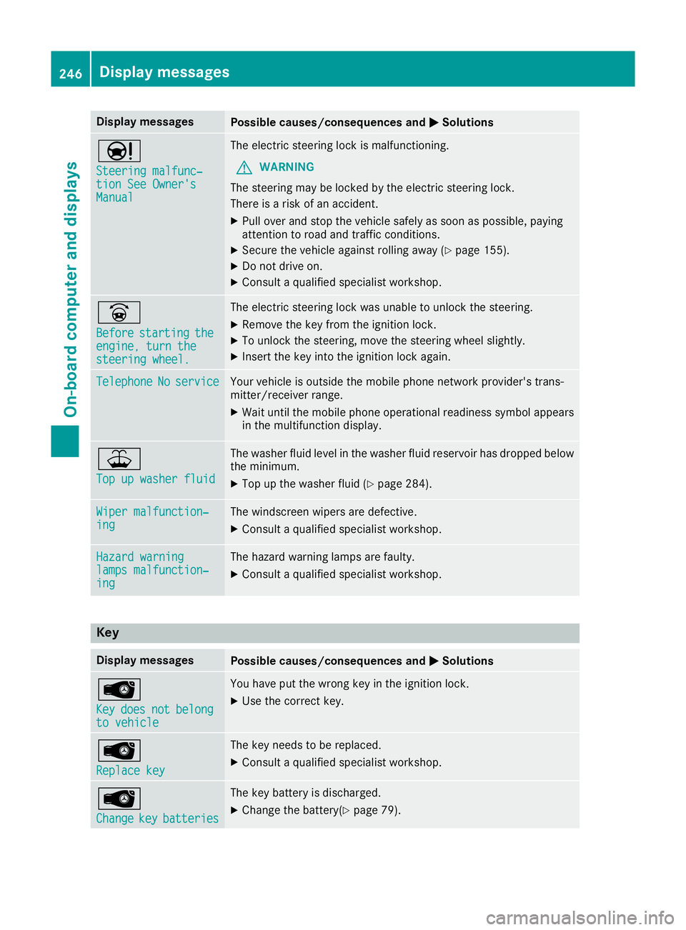
Display messages
Possible causes/consequences and
M
MSolutions Ð
Steering malfunc‐ Steering malfunc‐
tion See Owner's tion See Owner's
Manual Manual The electric steering lock is malfunctioning.
G WARNING
The steering may be locked by the electric steering lock.
There is a risk of an accident.
X Pull over and stop the vehicle safely as soon as possible, paying
attention to road and traffic conditions.
X Secure the vehicle against rolling away (Y page 155).
X Do not drive on.
X Consult a qualified specialist workshop. _
Before Before
starting
starting the
the
engine, turn the
engine, turn the
steering wheel. steering wheel. The electric steering lock was unable to unlock the steering.
X Remove the key from the ignition lock.
X To unlock the steering, move the steering wheel slightly.
X Insert the key into the ignition lock again. Telephone
Telephone
No
Noservice
service Your vehicle is outside the mobile phone network provider's trans-
mitter/receiver range.
X Wait until the mobile phone operational readiness symbol appears
in the multifunction display. ¥
Top up washer fluid Top up washer fluid The washer fluid level in the washer fluid reservoir has dropped below
the minimum.
X Top up the washer fluid (Y page 284).Wiper malfunction‐
Wiper malfunction‐
ing ing The windscreen wipers are defective.
X Consult a qualified specialist workshop. Hazard warning
Hazard warning
lamps malfunction‐ lamps malfunction‐
ing ing The hazard warning lamps are faulty.
X Consult a qualified specialist workshop. Key
Display messages
Possible causes/consequences and
M
MSolutions Â
Key Key
does
does not
notbelong
belong
to vehicle
to vehicle You have put the wrong key in the ignition lock.
X Use the correct key. Â
Replace key Replace key The key needs to be replaced.
X Consult a qualified specialist workshop. Â
Change Change
key
keybatteries
batteries The key battery is discharged.
X Change the battery(Y page 79).246
Display
messagesOn-board computer and displays
Page 250 of 345

Display messages
Possible causes/consequences and
M
MSolutions Â
Key not detected Key not detected
(red display message) The key is not in the vehicle.
A warning tone also sounds.
If the engine is switched off, you can no longer lock the vehicle cen-
trally or start the engine.
X Pull over and stop the vehicle safely as soon as possible, paying
attention to road and traffic conditions.
X Secure the vehicle against rolling away (Y page 155).
X Locate the key. Because there is interference from a strong source of radio waves, the
key is not detected whilst the engine is running.
A warning tone also sounds.
X Pull over and stop the vehicle safely as soon as possible, paying
attention to road and traffic conditions.
X Secure the vehicle against rolling away (Y page 155).
X Insert the key into the ignition lock and bring into key mode. Â
Key not detected Key not detected
(white display message) The key is currently undetected.
X Change the location of the key in the vehicle.
If the key still cannot be detected:
X Operate the vehicle with the key in the ignition lock if necessary. Â
Remove Remove
starting
starting but‐
but‐
ton,
ton, then
theninsert
insert key
key The key is continually undetected.
The key detection function has a temporary malfunction or is faulty. A
warning tone also sounds.
X Insert the key into the ignition lock and turn it to the desired posi-
tion.
X Consult a qualified specialist workshop. Warning and indicator lamps in the instrument cluster
General notes
Some systems perform a self test when the ignition is switched on. Some warning and indicator
lamps may temporarily switch on or flash during the test. This behaviour is nothing to be concerned about.
The warning and indicator lamps will alert you to a malfunction if they switch on or flash after the
engine is started or while driving. Wa
rning and indi cator lamps in the instrument cluster
247On-board computer and displays Z
Page 265 of 345

X
Select Town
Town .
The town in which the vehicle is currently
located (current vehicle position) is at the top.
Below this, you will see locations for which
route guidance has already been carried out.
X Enter the town.
The Gsymbol: the location is contained on
the digital map multiple times.
X To switch to the list: slide5the control-
ler.
X Select the location.
If available, the postcode is shown. If there
are different postcodes available for the loca-
tion, the corresponding digits are displayed
with an X
X.
X Enter the street and house number.
The address is in the menu.
Further options for destination entry:
R search for a keyword
The keyword search finds destinations using
fragments of words.
R select the last destination
R select a contact
R select a POI
You can search for a POI by location, name or
telephone number.
R select destination on the map
R enter intermediate destination
You can map the route to the destination
yourself with up to four intermediate destina-
tions.
R select travel guide destination (only available
for selected European countries)
R select destinations from Mercedes-Benz
Apps
R select geo-coordinates
Calculating the route Prerequisite: the address has been entered and
is in the menu.
X Select Start StartorContinue
Continue .
The route is calculated with the selected route
type and the selected route options. If route guidance has already been activated,
a prompt will appear asking whether you wish to end the current route guidance.
X Select Cancel
Cancel current
current route
routeguidance
guidance or
Set as intermediate destination
Set as intermediate destination.
Cancel current route guidance Cancel current route guidance cancels
the current route guidance and starts route
calculation to the new destination.
Set as intermediate destination
Set as intermediate destination adds
the new destination in addition to the existing destination and opens the intermediate des-
tinations list. Connecting the mobile phone
Requirements For telephony via the Bluetooth
®
interface, you
require a Bluetooth ®
-capable mobile phone. The
mobile phone must support Hands-Free Profile
1.0 or above.
Multimedia system:
X Select Vehicle VehicleQ System set‐
System set‐
tings
tingsQActivate Bluetooth Activate Bluetooth.
X Activate Bluetooth ®
O.
Mobile phone:
X Activate Bluetooth ®
and, if necessary, Blue-
tooth ®
visibility for other devices (see the
manufacturer's operating instructions).
The Bluetooth ®
device names for all of one man-
ufacturer's products might be identical. To
make it possible to clearly identify your mobile
phone, change the device name (see the man-
ufacturer's operating instructions).
If the mobile phone supports the PBAP (Phone
Book Access Profile) and MAP (Message
Access Profile) Bluetooth ®
profiles, the follow-
ing information will be transmitted after you
connect:
R Phone book
R Call lists
R Text messages and e-mails
i Further information on suitable mobile
phones can be found at: http://
www.mercedes-benz.com/connect 262
Operating systemMultimedia system
Page 266 of 345
Searching for and authorising (connect-
ing) a mobile phone Before using your mobile phone with the multi-
media system for the first time, you will need to
search for the phone and then authorise (con-
nect) it. Depending on the mobile phone, author- isation takes place by means of Secure Simple
Pairing or by entering a passkey. The multimedia
system automatically makes the procedure that is relevant for your mobile phone available. The
mobile phone is always connected automati-
cally after authorisation. Further information on using a mobile phone with the multimedia sys-
tem (see the Digital Owner's Manual).
If the multimedia system does not detect your
mobile phone, this may be due to particular
security settings on your mobile phone (see the
manufacturer's operating instructions).
Only one mobile phone can be connected to the multimedia system at any one time.
Searching for a mobile phone
Multimedia system:
X Select Tel/
Tel/®QConnect Connect
device deviceQSearch for phones Search for phonesQStart Start
search
search.
The available mobile phones are displayed.
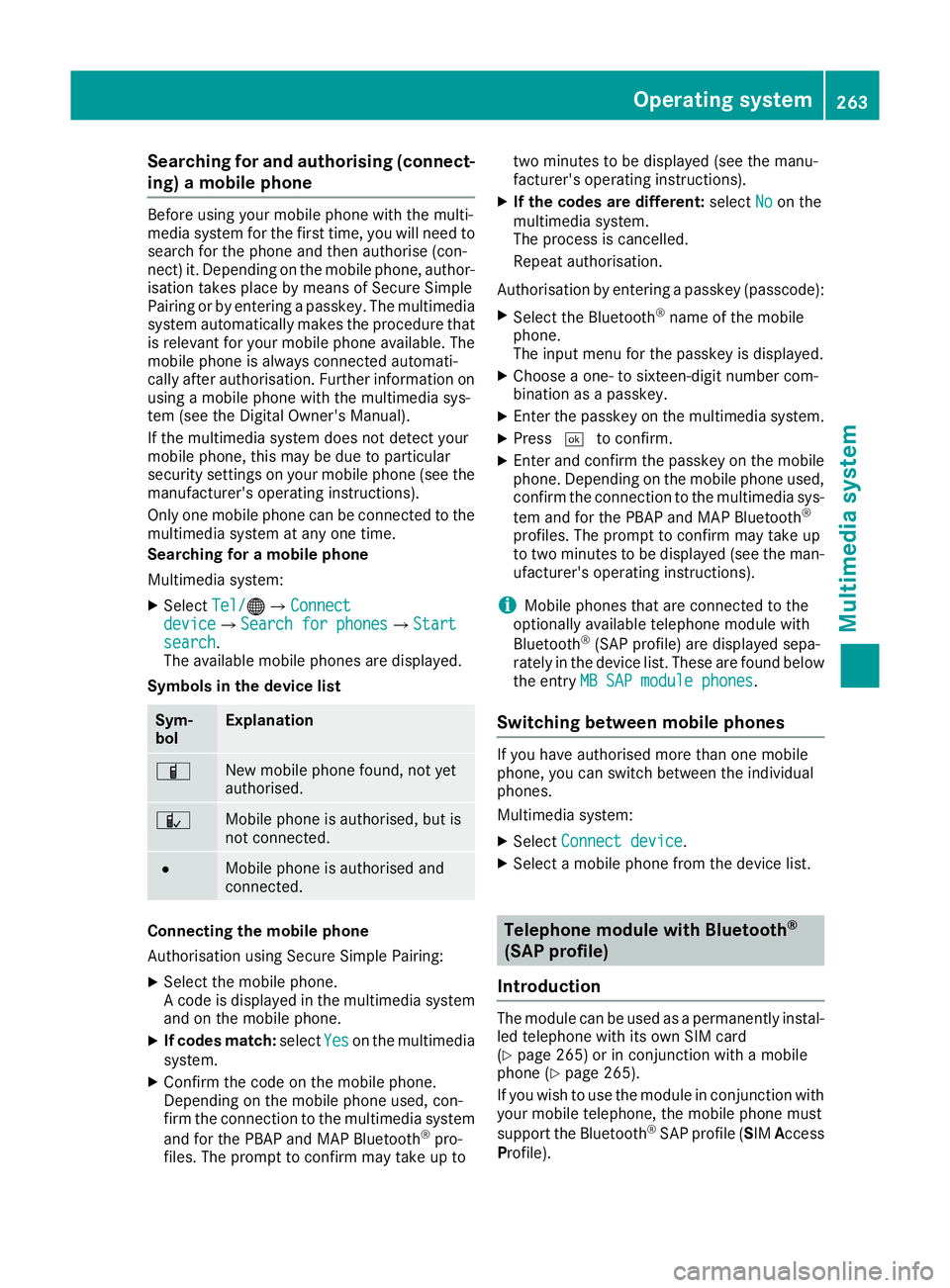
Symbols in the device list Sym-
bol Explanation
Ï
New mobile phone found, not yet
authorised.
Ñ
Mobile phone is authorised, but is
not connected. #
Mobile phone is authorised and
connected.
Connecting the mobile phone
Authorisation using Secure Simple Pairing:
X Select the mobile phone.
A code is displayed in the multimedia system
and on the mobile phone.
X If codes match: selectYes Yeson the multimedia
system.
X Confirm the code on the mobile phone.
Depending on the mobile phone used, con-
firm the connection to the multimedia system
and for the PBAP and MAP Bluetooth ®
pro-
files. The prompt to confirm may take up to two minutes to be displayed (see the manu-
facturer's operating instructions).
X If the codes are different: selectNo
No on the
multimedia system.
The process is cancelled.
Repeat authorisation.
Authorisation by entering a passkey (passcode): X Select the Bluetooth ®
name of the mobile
phone.
The input menu for the passkey is displayed.
X Choose a one- to sixteen-digit number com-
bination as a passkey.
X Enter the passkey on the multimedia system.
X Press ¬to confirm.
X Enter and confirm the passkey on the mobile
phone. Depending on the mobile phone used,
confirm the connection to the multimedia sys-
tem and for the PBAP and MAP Bluetooth ®
profiles. The prompt to confirm may take up
to two minutes to be displayed (see the man- ufacturer's operating instructions).
i Mobile phones that are connected to the
optionally available telephone module with
Bluetooth ®
(SAP profile) are displayed sepa-
rately in the device list. These are found below
the entry MB SAP module phones
MB SAP module phones.
Switching between mobile phones If you have authorised more than one mobile
phone, you can switch between the individual
phones.
Multimedia system:
X Select Connect device
Connect device.
X Select a mobile phone from the device list. Telephone module with Bluetooth
®
(SAP profile)
Introduction The module can be used as a permanently instal-
led telephone with its own SIM card
(Y page 265) or in conjunction with a mobile
phone (Y page 265).
If you wish to use the module in conjunction with
your mobile telephone, the mobile phone must
support the Bluetooth ®
SAP profile (SIM Access
Profile). Operating system
263Multimedia system Z
Page 279 of 345
X
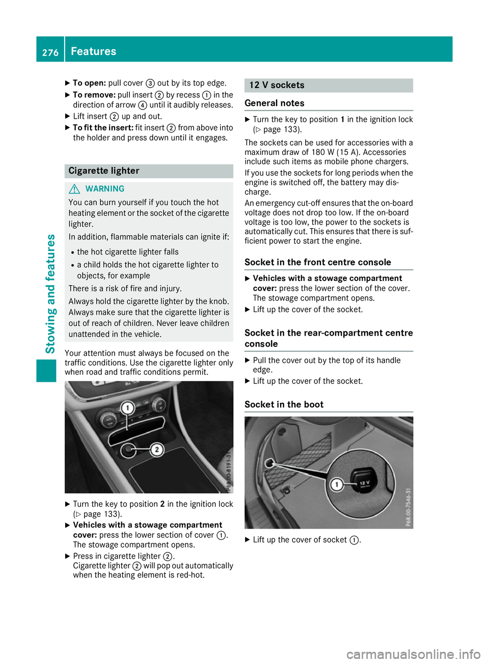
To open: pull cover =out by its top edge.
X To remove: pull insert;by recess :in the
direction of arrow ?until it audibly releases.
X Lift insert ;up and out.
X To fit the insert: fit insert;from above into
the holder and press down until it engages. Cigarette lighter
G
WARNING
You can burn yourself if you touch the hot
heating element or the socket of the cigarette lighter.
In addition, flammable materials can ignite if:
R the hot cigarette lighter falls
R a child holds the hot cigarette lighter to
objects, for example
There is a risk of fire and injury.
Always hold the cigarette lighter by the knob.
Always make sure that the cigarette lighter is
out of reach of children. Never leave children unattended in the vehicle.
Your attention must always be focused on the
traffic conditions. Use the cigarette lighter only when road and traffic conditions permit. X
Turn the key to position 2in the ignition lock
(Y page 133).
X Vehicles with a stowage compartment
cover: press the lower section of cover :.
The stowage compartment opens.
X Press in cigarette lighter ;.
Cigarette lighter ;will pop out automatically
when the heating element is red-hot. 12 V sockets
General notes X
Turn the key to position 1in the ignition lock
(Y page 133).
The sockets can be used for accessories with a
maximum draw of 180 W(15 A). Accessories
include such items as mobile phone chargers.
If you use the sockets for long periods when the engine is switched off, the battery may dis-
charge.
An emergency cut-off ensures that the on-boardvoltage does not drop too low. If the on-board
voltage is too low, the power to the sockets is
automatically cut. This ensures that there is suf-
ficient power to start the engine.
Socket in the front centre console X
Vehicles with a stowage compartment
cover: press the lower section of the cover.
The stowage compartment opens.
X Lift up the cover of the socket.
Socket in the rear-compartment centre
console X
Pull the cover out by the top of its handle
edge.
X Lift up the cover of the socket.
Socket in the boot X
Lift up the cover of socket :.276
FeaturesStowing and fea
tures
Page 281 of 345
X
Open the telephone compartment
(Y page 270).
X Place the mobile phone bracket into the pre-
installed fitting; see the separate installation
instructions for the mobile phone fitting.
X Insert the mobile phone into the mobile phone
bracket; see the separate installation instruc- tions for the mobile phone fitting.
i The mobile phone can also be operated
without being in the bracket. However, the
charging function and aerial function are not
available.
In order to use Bluetooth ®
(SAP profile) on your
telephone module, you must first insert the tele-
phone module into the pre-installed fitting. This connects it to the exterior aerial. If you wish to
charge the mobile phone, you must connect it to
a USB port.
Further information on the telephone module
with Bluetooth ®
(SAP profile) can be found in the
Digital Owner's Manual.
Operating the mobile phone You can operate the phone using the
6and
~ buttons on the multifunction steering
wheel. You can operate other mobile phone
functions via the on-board computer
(Y page 207).
When you remove the key from the ignition lock, the mobile phone is disconnected from the vehi-cle. You can then no longer make calls using the
hands-free system.
If a call is active and you remove the key from
the ignition lock, the conversation is transferred
over to the mobile phone. It is then possible to
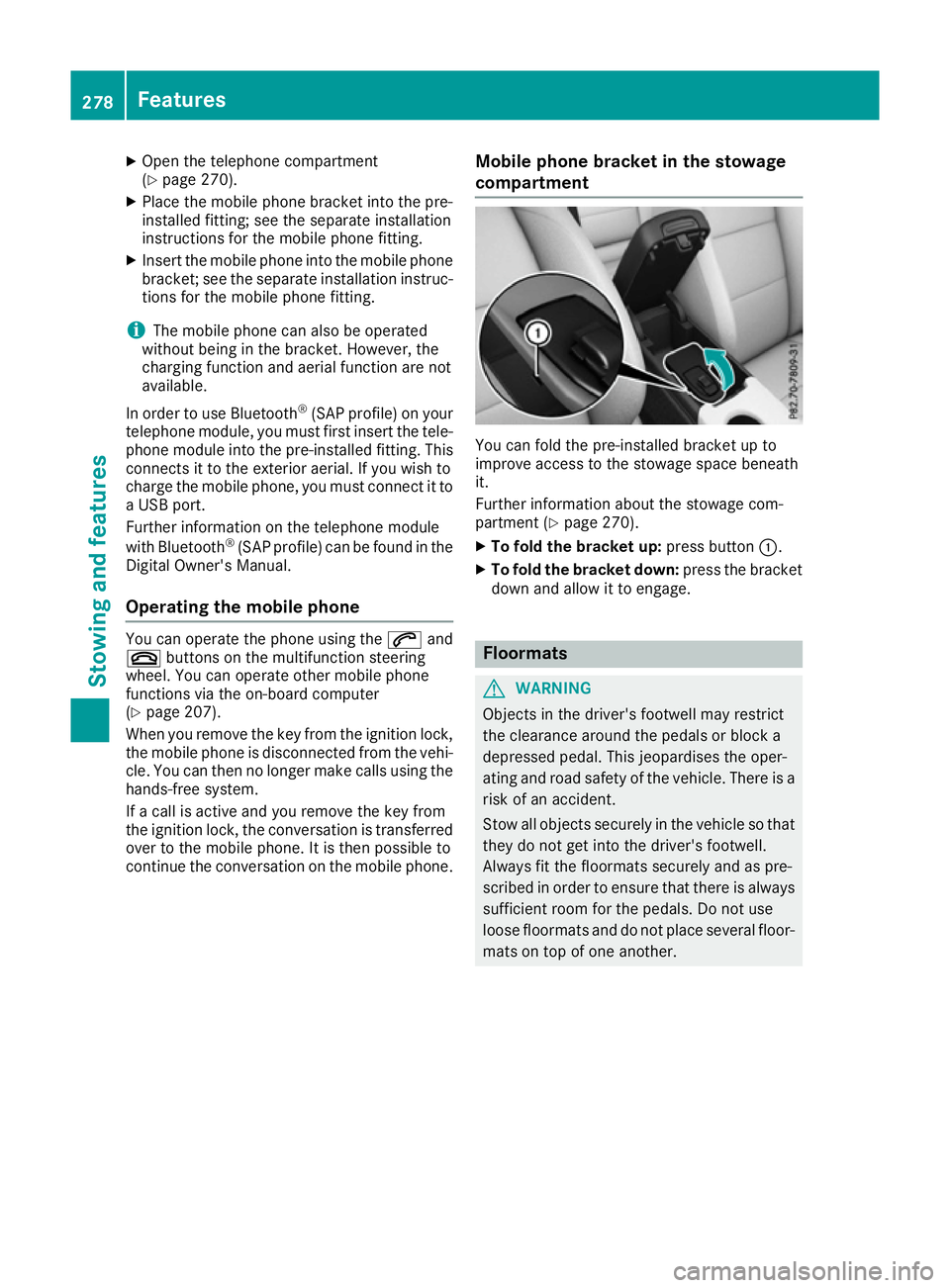
continue the conversation on the mobile phone. Mobile phone bracket in the stowage
compartment You can fold the pre-installed bracket up to
improve access to the stowage space beneath
it.
Further information about the stowage com-
partment (Y page 270).
X To fold the bracket up: press button:.
X To fold the bracket down: press the bracket
down and allow it to engage. Floormats
G
WARNING
Objects in the driver's footwell may restrict
the clearance around the pedals or block a
depressed pedal. This jeopardises the oper-
ating and road safety of the vehicle. There is a risk of an accident.
Stow all objects securely in the vehicle so that
they do not get into the driver's footwell.
Always fit the floormats securely and as pre-
scribed in order to ensure that there is always sufficient room for the pedals. Do not use
loose floormats and do not place several floor-mats on top of one another. 278
FeaturesStowing and features